MIM2023: Industry insights from the International Conference on Injection Molding of Metals, Ceramics and Carbides
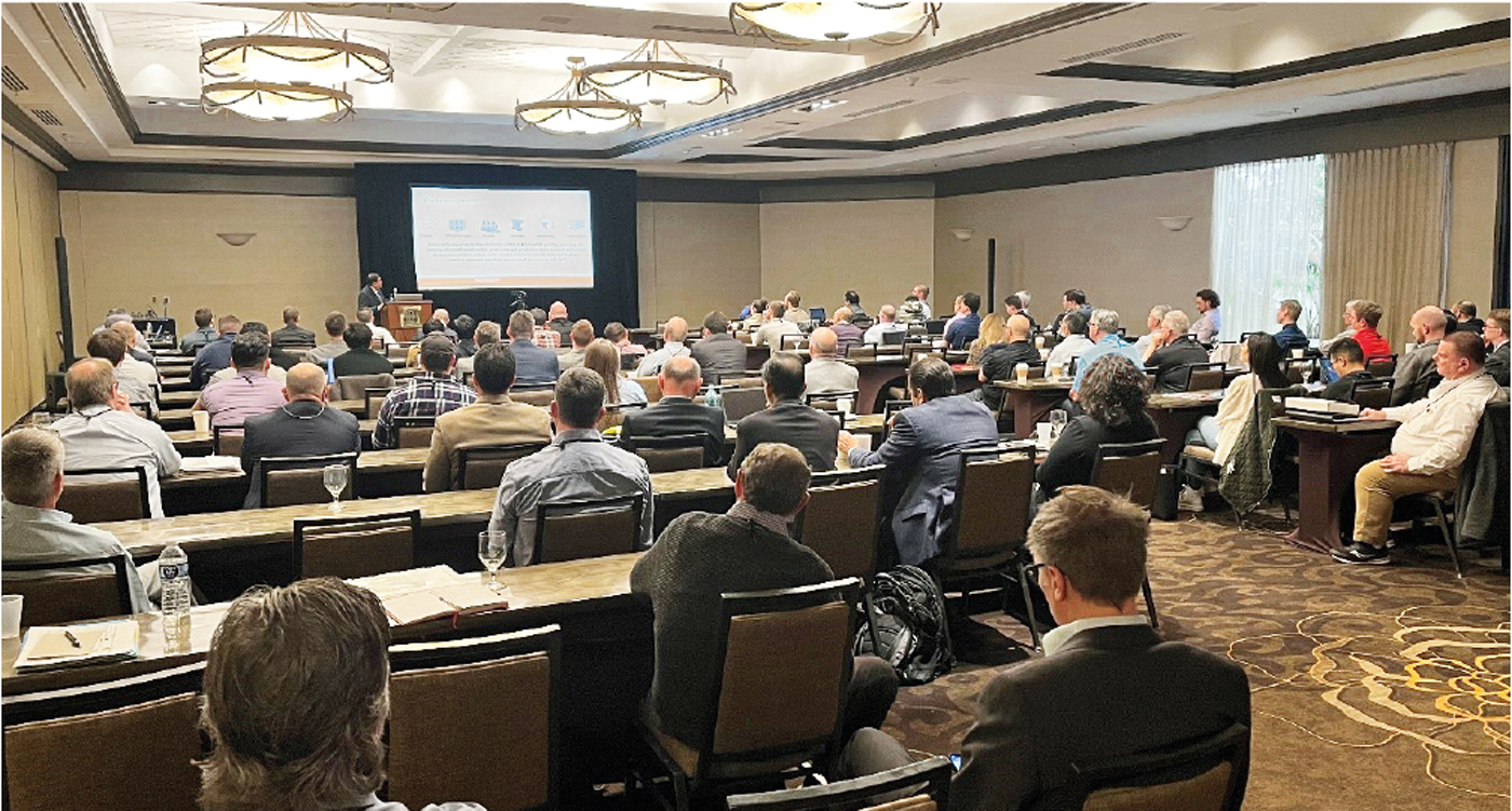
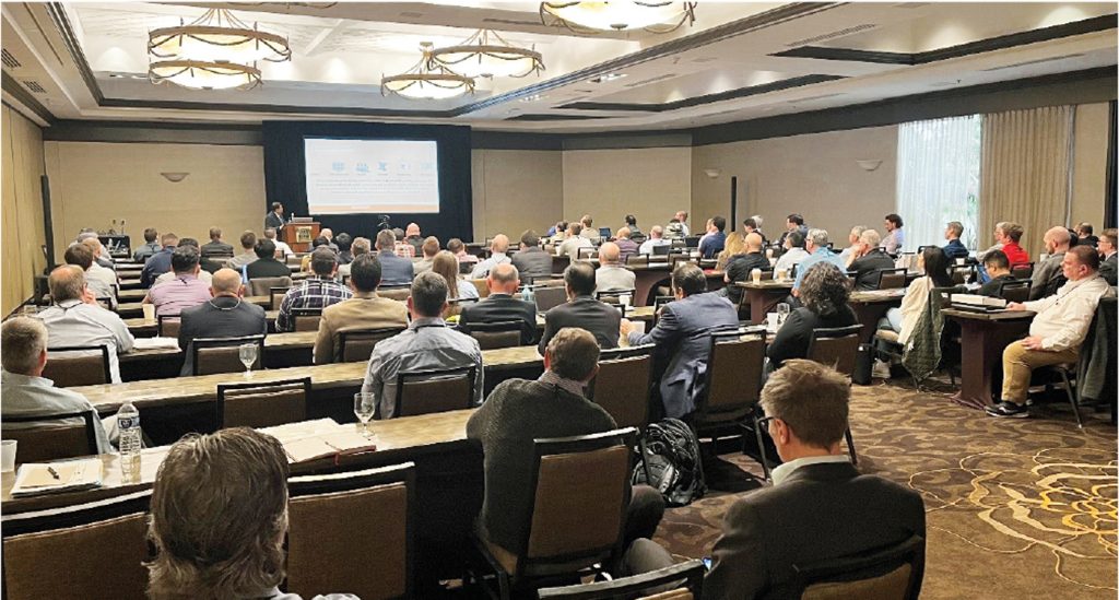
The 2023 International Conference on Injection Moulding of Metals, Ceramics and Carbides (MIM2023), organised by the Metal Powder Industries Federation (MPIF)’s Metal Injection Molding Association (MIMA), was held in Costa Mesa, California, USA, from February 27 to March 1, 2023. As well as being the annual meeting point of the US Metal Injection Molding community, the event attracts an international audience and has broadened in scope to include sinter-based Additive Manufacturing processes. Dr Animesh Bose reviews some highlights from the MIM2023 technical programme. First published in PIM International Vol. 17 No. 2, Summer 2023 | 20 minute read | View on Issuu | Download PDF
The objective of MIM2023 was to survey the advancements in the area of injection moulding of metals, ceramics and carbides and support the efforts of technology transfer across different areas of Metal Injection Moulding (MIM). It also looked to focus on new developments that contribute to the growth of MIM, and keep the community appraised and updated about other technologies, primarily sinter-based Additive Manufacturing, that could be complementary, but also pose a threat to MIM in some areas.
Although MIM2023 was organised as a hybrid event, including both online and in-person presentations, the in-person presentations significantly outnumbered the virtual ones. This was an extremely good sign for the industry, which is rebounding back to its pre-COVID days with attendance at the conference climbing to 138 and participation from 11 countries. International participation was still slightly weaker than expected, but is anticipated to bounce back next year.
In addition to the main technical sessions, the wider event also featured the long-established one-day PIM tutorial, presented for many years by Prof Randall German and now by Matt Bulger, former president of the MPIF’s Metal Injection Molding Association (MIMA). MIMA standards committee, board of directors and members meetings also took place, as well as short commercial process and product innovation presentations and a tabletop exhibition.
Megatrends in near-net-shape manufacturing
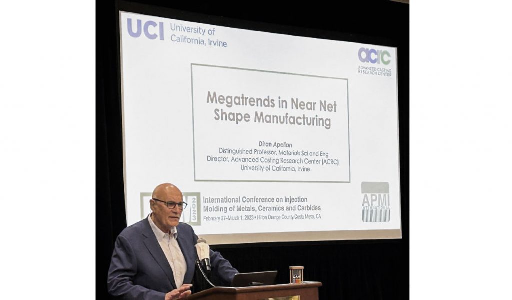
MIM2023’s opening keynote was delivered by Diran Apelian, Distinguished Professor, Materials Science and Engineering, at the University of California, Irvine, USA. This opening keynote presentation was on an extremely thought-provoking topic entitled Megatrends in Near-Net-Shape Manufacturing. After his initial introduction, Apelian showed a slide stating ‘CHANGE: It is the Universal Constant’ which set the tone for the remainder of his presentation. The presentation was divided into four broad segments: digitisation/industry 4.2TM/data science; sustainability, including resource recovery and decarbonistion; process innovations; and talentism (not capitalism nor socialism).

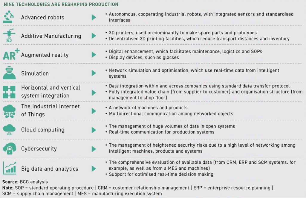
The presentation touched on the nine technologies that are reshaping production (Fig. 3). According to Prof Apelian, Industry 4.0 was going to consist of automation, connection, cloud computing, IOT, big data and system integration. Automation and Artificial Intelligence (AI) are expected to play a key role in the transformation to Industry 4.0. To emphasise that point, the presentation provided an interesting statistic on the change in stock values of these companies, compared to the Dow Jones Industrial Average, between 2 January 2020 to 4 January 2021. The compiled data showed that the Dow Jones had increased by 5%, but the majority of companies involved in automation and AI (ten different companies) had increased from 20 to 68% over the same period.
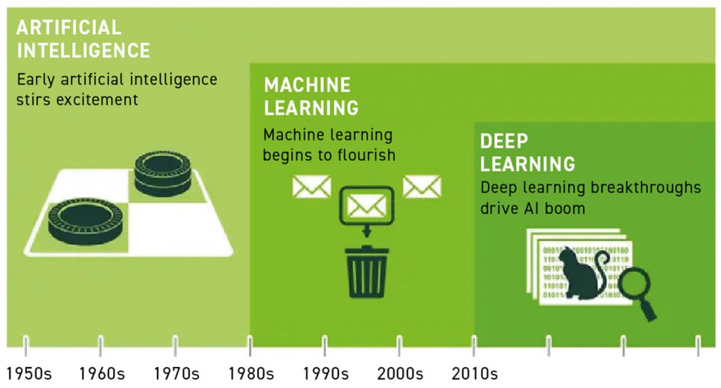
It was stated that, “AI and robotics will transform tasks rather than make humans obsolete. The impact of AI and robotics depends on how we adopt them.” Machine Learning (ML), which is a branch of AI where one constructs computer algorithms to mimic tasks commonly performed by humans, is expected to play a critical role in the industrial transformation. This statement has reportedly been supported by Microsoft’s Bill Gates who has stated that “a breakthrough in ML would be worth ten Microsofts.” Deep learning, which is a subset of ML, is creating large disruptions and has the potential to keep driving the AI boom. A schematic of the timeline of AI, ML and deep learning is shown in Fig. 4.
The drive for sustainability is directly connected to the growth in the world’s population, which jumped from 1.6 billion in 1900 to 6.1 billion in 2000 and 7.8 billion in 2020. This increase in population, along with the demands placed on the world’s material resources, has created the urgent need to focus on sustainability. The areas of materials and advanced manufacturing will have a direct impact on energy and climate change, food and water, housing (shelter), mobility (transportation, cyber mobility) and health.
For sustainable development, the key areas of focus need to be production waste, post-consumer waste and materials for clean energy. The area of processing innovations is also intimately tied with sustainability. Recycling and recovery of materials (especially rare earth materials used in batteries) is critical in process innovations.

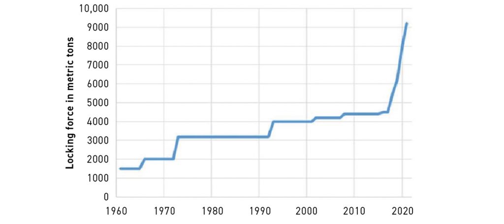
An interesting area of process innovation is gigacasting in the automotive industry, leading to a simplification of vehicle structures. This innovation has the potential to reduce the number of automotive parts needed for a car body structure from 171 to two, and require 1600 fewer welds. To keep up with the demand for large casting sizes, the die cast machine size range has increased dramatically over time. Prof Apelian pointed out that LK, the global leader in hot chamber and cold chamber die casting machines, has increased the locking force of its hot chamber die cast machine cells from 2000 to 12,000 tonnes since 1970 (Fig. 5).
Another important area that is tied to process innovations is the issue of conformal cooling in casting dies and injection moulding machines. This requires improved thermal management that allows shorter cycle times, improved mechanical properties, complicated geometry (thick and thin sections), uniform die/tool temperature, and better temperature control. AM is playing a key role in this area by allowing for increased tool complexity with fewer components and reduced lead times. Improvements in the performance of the tools are also dictated by new materials that can provide high thermal conductivity, high-temperature resistance and, thereby, result in extended tooling life.

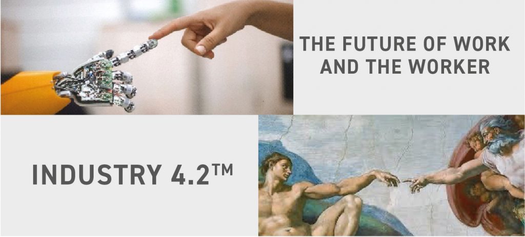
Prof Apelian acknowledged that talent is a scarce commodity and he quoted Klaus Schwab from the World Economic Forum, who stated that, “in the 4th Industrial Revolution, it is all about talentism; not capitalism nor socialism.” Development and utilisation of the talent pool will be the key to the success of the 4th Industrial Revolution. An illustration of the dream of Industry 4.2TM and the future of work and the worker is shown in Fig. 6.
Sinter-based AM technologies
It is of interest to note that the MIM conferences organised by MPIF have, over the past five years, seen a steady increase in the number of AM presentations. This trend has been driven primarily by the similarities in some of the sinter-based AM processes and Metal Injection Moulding as well as the ongoing discussions about whether these AM technologies are complementary or a threat to MIM. Recent years have also witnessed the proliferation of numerous sinter-based AM technologies.
It was felt that there was a need for a presentation discussing several relevant sinter-based AM technologies. This was covered in a presentation by Dr Animesh Bose (yours truly), formerly with Desktop Metal and now with Optimus Alloys, entitled “Review of Some Sinter-Based Metal AM Technologies.” The presentation illustrated the similarities and the differences between the majority of sinter-based AM processes and MIM, as shown in Fig. 7.
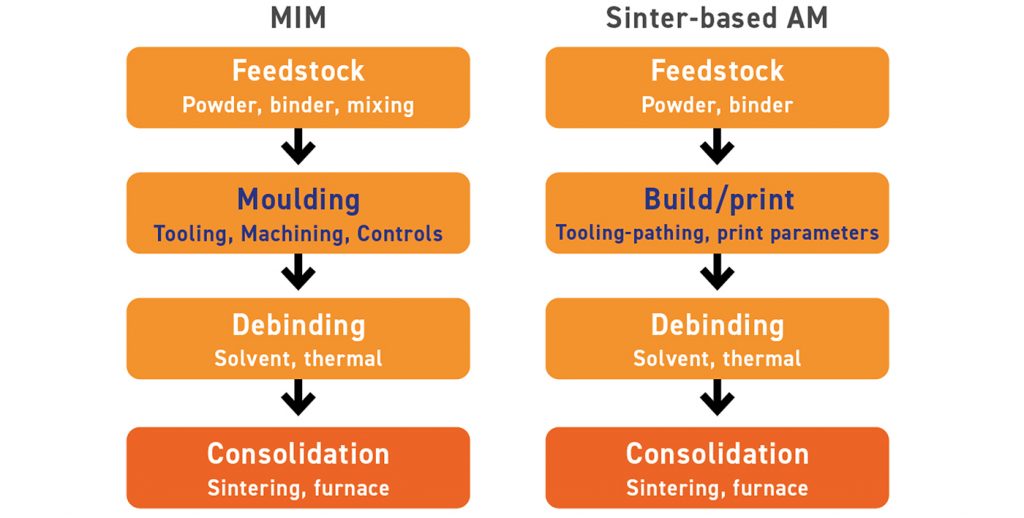
The differences between single-step and multi-step processes, as outlined by ISO/ASTM 52900:2015, were discussed. It was pointed out that almost all the sinter-based AM processes were multi-step processes, where the parts are fabricated in two or more distinctly different operations. The first operation typically produces the basic geometry of the part and the subsequent step(s) results in the consolidation of the part to achieve the final properties (dependent on the desired material) of the part.
The presentation covered the broad technologies of Material Extrusion (MEX)-based processes, where the material is selectively dispensed through a nozzle or orifice. The material being extruded can become the final part itself, as in the case of pure polymer extrusion or hot extruding a metallic wire or polymer loaded with metal powder to form the final part.
Contrastingly, a MIM-type of feedstock, where metal powder is mixed with organic binders to form a feedstock, is extruded through a nozzle to build a geometric shape that is subsequently subjected to debinding and a consolidation step to result in the final part. This multi-step process has similarities with the MIM process, except for the geometric shaping, which is accomplished by a build process, or printing, instead of moulding.
Several processing techniques based on the MEX process, developed by different companies, were discussed and some applications were highlighted. Various commercial solutions based on the principle of MEX, including those using feedstock in the form of a filament or rod (Desktop Metal, MarkForged) and pellet-based extrusion processes (Pollen and AIM 3D), as well as extrusion of gel-based and paste-based feedstocks, were touched upon.
Another major process that was covered was Vat Photopolymerisation (VPP), which is based on photopolymerisation of a metal or ceramic containing slurry using a digital light engine. Some of the processes that have evolved based on this technology by different companies include Lithoz, Incus, Holo, Trio Labs and Tethon 3D.
Another interesting set of solutions that were covered include hybrid processes that combine additive and subtractive technologies to produce the final product. Some of the companies that are using these hybrid technologies include 3DEO, Mantle and Tritone (MoldJet). The presentation also discussed some of the other sinter-based AM processes, such as screen printing, Cold Metal Fusion and Nanoparticle Jetting.
A major part of the presentation was based on Binder Jetting (BJT) technology, which has gained the best traction among all the sinter-based AM processes thanks to its promise of high-volume production capability at a low cost. The presentation pointed out that some of the technologies are complementary to MIM, supporting MIM companies in terms of quick tooling and even rapid prototyping of actual metal parts. However, it was pointed out that some processes, such as BJT, can also pose competition to MIM due to their ability to fabricate parts with high productivity and without the requirement of any tooling.
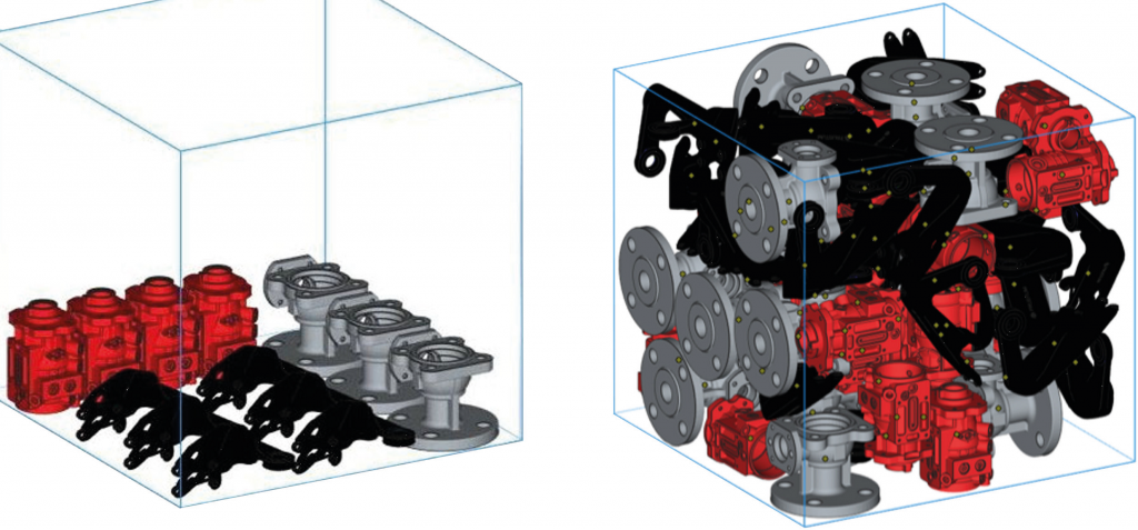
Fig. 8 shows the packing of different parts in a Desktop Metal BJT process. The picture on the top shows a single-layer stacking of three different parts (housing, valve body and brackets) in a build box, whereas the picture on the bottom shows the optimised packing of the same three parts for the complete build box.
A MIM design challenge: 316L elevator button body
The current scenario, where AM can be complementary to MIM, was very well covered in the presentation by Gaetano Mariella of PTI Tech Inc., New Jersey, USA. In his presentation entitled ‘Utilizing Metal Injection Molding and AM Binder Jetting in the Production of a 316L Industrial Part’, Gaetano detailed a case study that was initiated due to COVID-19. PTI was approached by a major elevator company to solve a problem with their current elevator button panels.
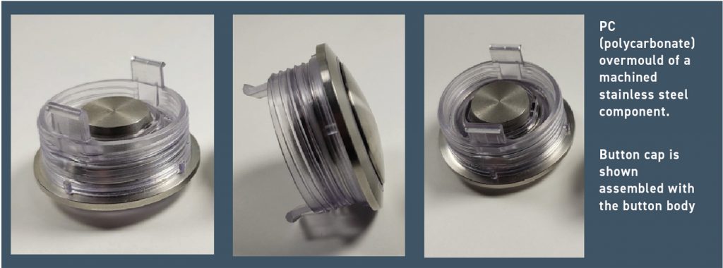
As can be imagined, these elevator button panels are high-touch areas by the public. Due to the COVID-19 pandemic, these button panels were subject to the widespread and increased use of chemical disinfectants to limit the spread of the virus. However, this increased use of various solvents and disinfectants was rapidly degrading the current legacy multi-part elevator button assemblies. Fig. 9 shows a picture of the current legacy overmoulded button assembly.
The design challenge faced by PTI was to consolidate the button assembly design and eliminate the polymer overmould. The designing and engineering of flexing retaining tabs and assembly threads in an all-MIM 316L button body design was challenging. Over and above that, the retaining tabs needed to be thin enough (~0.030”) to flex them by hand yet retain their shape without cracking.
However, the primary reason for incorporating AM was the tight timeline for project completion. PTI needed a rapid prototype technology that could manufacture production-representative parts that could then dovetail into large-volume MIM production. Binder Jetting of 316L was used to solve the issues. Various iterations of the button body and the button cap were fabricated to test: a) various retaining tab cross sections; b) sintered dimensional control; c) machined surface finish; and d) final assembly design. For example, Fig. 10 shows the results of button body tab flexing, which was possible due to the thin tab made from 316L. All the tests, including the flexing, were completed without hard tooling and the finished prototype parts were successfully delivered to the customer before any tool steel for a mould was cut.
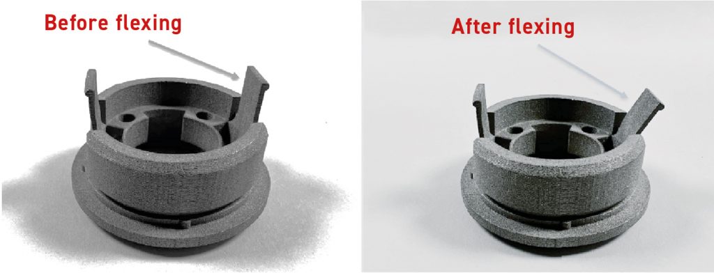
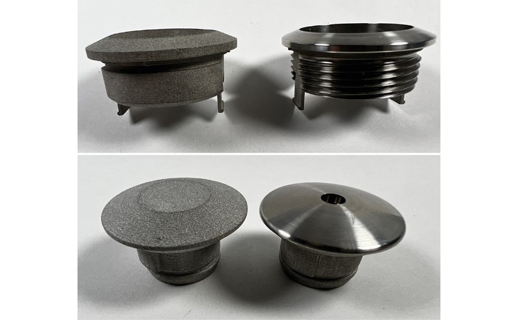
Fig. 10 shows the AM button body and the button cap in both the as-sintered and machined conditions. The rapid prototyping using the BJT process was the key to the success of the project. Once the design and properties were achieved (that satisfied the customer), attention was focused on MIM for high-volume production of the actual components.
Multi-cavity hard MIM tooling was designed and manufactured by PTI using novel gating techniques, as well as novel techniques that were developed to release and eject the complex component geometry. Custom sintering setters were developed to ensure the perpendicularity of extended thin retaining tabs while maintaining the flatness and concentricity of the button body.
The initial time and cost savings were significant when using the Binder Jetting process for prototyping. In addition, the process dovetailed very well with the MIM production process. The result was a cost-effective all-stainless steel industrial button assembly impervious to solvent and disinfectant chemicals while maintaining the same design as the mating electrical panel assembly.
This presentation highlighted a case where a sinter-based AM process was successfully used as the perfect rapid prototyping method to establish the form, fit and function of the intended part, which was subsequently transitioned to high volume, near-net-shaped MIM components that were finally machined to yield the desired parts.
High-density powders by Uniformity Labs

Another interesting presentation from Uniformity Labs (UL), California, USA, was given by Dr Joseph Schramm, entitled ‘Performance of Highly Uniform High Density Multimodal Stainless Steel Powders in Metal Injection Molding.’ This presentation highlighted the benefits of designed multimodal powders to attain higher solids loading in MIM feedstocks. The presentation highlighted the ability of UL powders to attain high relative densities, approaching that of the densest crystalline particle packings, while retaining their ability to flow without phase separation. Fig. 12 shows a schematic of the densest natural crystalline packing of binary spheres and the UL maximally random jammed packing, both using a powder size ratio of 5:1. It can be seen that the UL powder can attain a packing density that is almost the same as the densest natural crystalline packing.
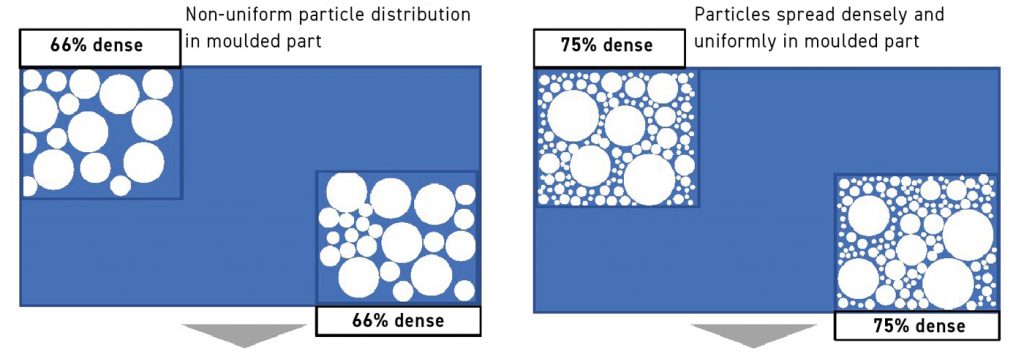
Fig. 13 shows a schematic comparing a non-uniform particle distribution in moulded parts (left) to a 75% dense loading where the particles are spread uniformly and maintain the same high density (right). Earlier investigations by UL showed the benefits of its multimodal, highly packed powder in Binder Jetting and whether these benefits could be translated to MIM.
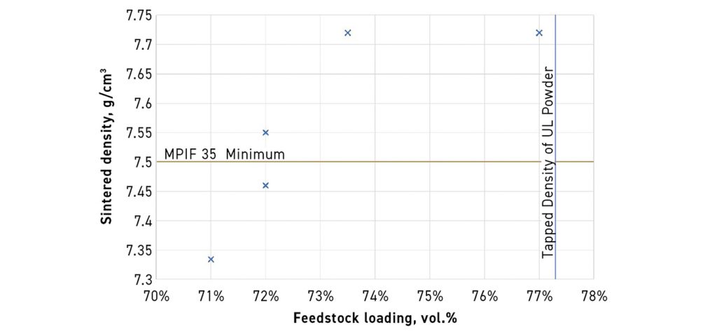
This work was done in collaboration with US MIM producer OptiMIM, based in Wilsonville, Oregon. UL 17-4 PH powders with a high tapped powder density (minimum –5.60 g/cm3; maximum –5.92 g/cm3) were converted into feedstock with loadings ranging from 71 to 77 vol.% (less than 4% binder by mass). The feedstocks were moulded into tensile bars and it was determined that all the loadings were mouldable without requiring any equipment modification.
Fig. 14 shows the variation in the sintered densities of MIM bars with different feedstock loadings. It is interesting to note that the moulded bars achieve a very high sintered density as feedstock loading approaches the tapped density of the powder. This property then translates into lower shrinkage of the MIM bars at higher loadings, which is possible using the UL powder. Typically, lower shrinkage leads to lower distortion. Thus, UL powders of high tap densities can be beneficial to the MIM industry.
Solvents used in debinding
A topic that often does not get the coverage that it deserves is that of the solvents used in debinding. This topic was covered in detail by David A Ferguson of MicroCare, LLC. His presentation entitled ‘Solvent Debinding Series: Update: Comparing Overall Efficiency of Various Solvent Mixtures’ discussed the current trends in solvent use and showed lab experiments of different solvents. During the presentation, David pointed out the issues with some of the popular solvents, as outlined below:
- Heptane and hexane: flammable; require drying time due to their high boiling point
- Water: limited to water-soluble binders only
- Chlorinated solvents: toxicity/environmental hazards
- Trichloroethylene: EPA deemed “unreasonable risk as a solvent in liquid degreaser/cleaner” (NPRM – Q1 2023)
- Perchloroethylene: EPA deemed “unreasonable risk as a solvent for open-top batch vapor degreaser” (NPRM – Q1 2023)
- N-propyl bromide: toxicity/environmental hazard EPA deemed “unreasonable risk as a solvent for cleaning and degreasing in vapor degreaser” (NPRM – Q1 2023)
- Fluorinated mixtures: non-flammable, lower surface tension, faster drying time.
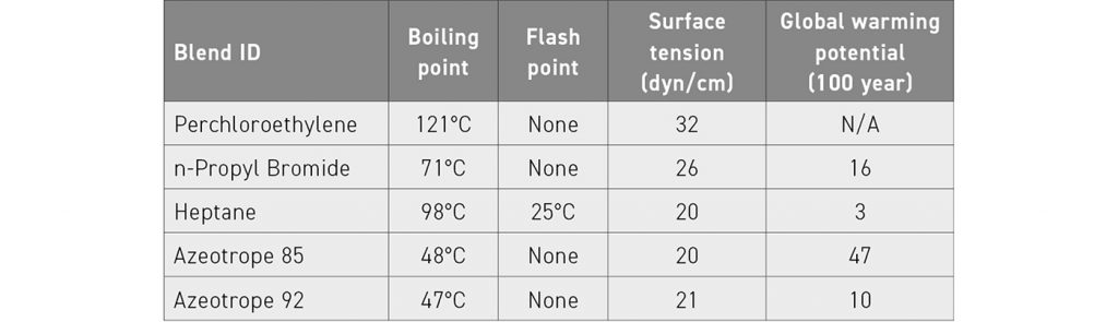
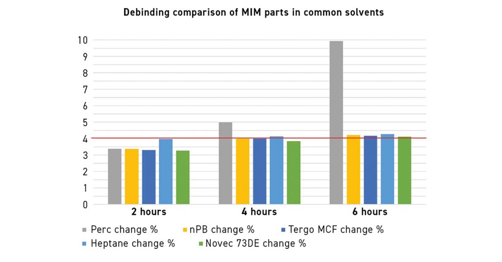
Laboratory experiments were carried out and five solvents were chosen. The solvent properties are outlined in Table 1 (Note: Tergo MCF is azeotrope 92 and Novec 73DE is azeotrope 85). A comparison of the amount of binder removed by different solvents is shown in Fig. 15. The time that it takes for the solvents to be removed at ambient temperature is also an important factor (Fig. 16). The overall debinding process efficiencies for different solvents are shown in Table 2. The presentation concluded with the following summary:
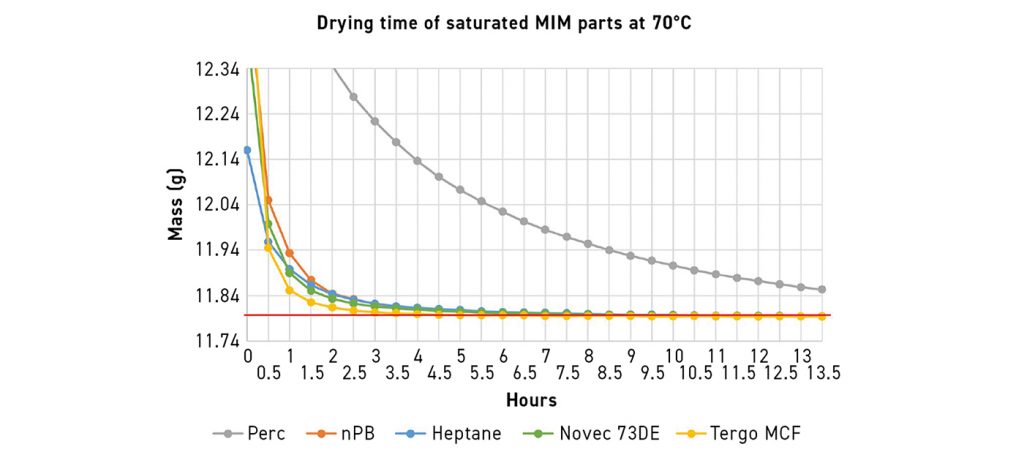
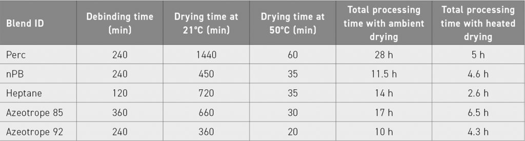
Heptane
This had the fastest debinding time with an average of 0.7 h/cm3. Heptane also had the fastest overall processing time for debinding and heated drying with a requirement of 0.8 h/cm3. Flammable liquid requires special equipment; not a significant toxicity hazard.
Azeotrope 92 (Tergo MCF)
This offered the fastest overall processing time for debinding and ambient drying with a requirement of 3.3 h/cm3. This azeotrope also had the second fastest overall processing time for debinding with heated drying displaying an average rate of 1.4 h/cm3. Non-flammable liquid can be used in open-top or vacuum equipment; not a significant toxicity hazard.
N-propyl bromide
This had similar results to Tergo MCF. Non-flammable liquid can be used in open-top or vacuum equipment. The toxicity concerns with this include carcinogenicity, as a result the solvent is facing regulatory action and phase-out.
The Hammer Lab35 metal AM solution from Incus
One sinter-based AM process that has the potential to compete with MIM is Incus’s process based on Vat Photopolymerisation. A presentation of this process was given by Dr György Harakály of Incus, Austria, entitled Lithography-based Metal Manufacturing. His paper outlined the advantages of this process including the ability to produce complex green parts in a small- to medium-size range (1–200 g component mass), the highest resolution and surface aesthetics of metal AM processes, a wide range of materials with the possibility of processing non-flowable and non-weldable materials, a simple production process with easy preparation of printing jobs and quick exchange of materials, and safe working environment with no metal dust or high-power laser.
The presentation discussed the company’s lab scale machine that is currently on the market (Hammer Lab35) and mentioned their next production machine, known as Hammer Pro, which will have more than six times the build area compared to the lab version. This will enable the production of larger parts as well as parts in higher production volumes at a lower cost. Some of the details of the lab-size machine are shown in Table 3.
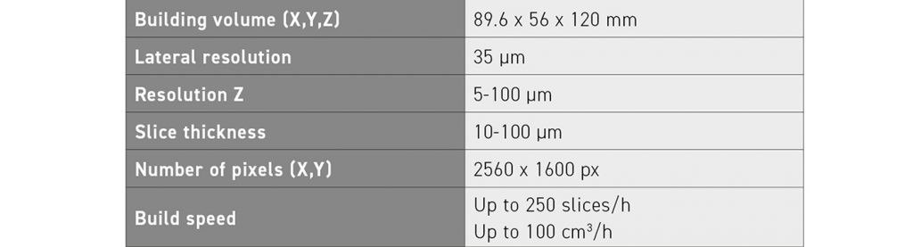
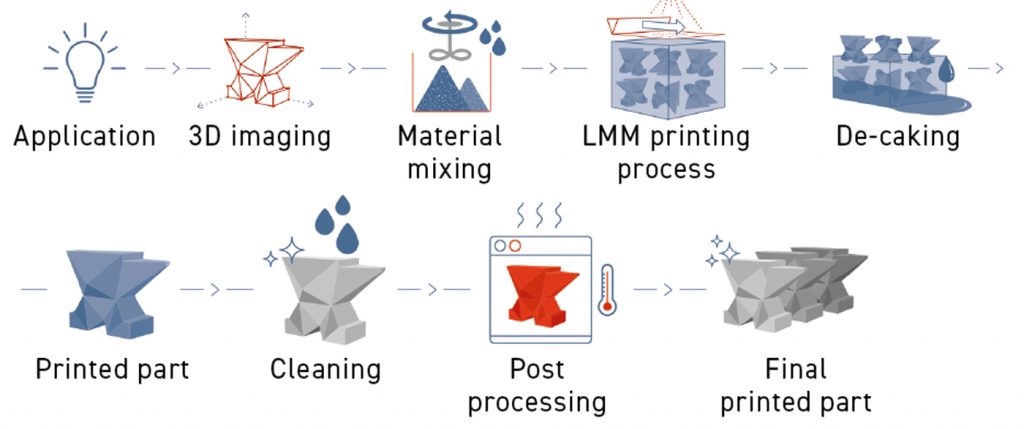
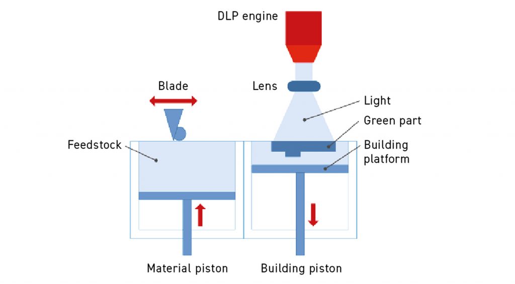
The as-sintered surface roughness of the process is around 2.17 µm Ra, which can be reduced to 0.067 µm with surface treatment. A schematic of the overall Incus lithography-based metal manufacturing process steps is shown in Fig. 17 and the detailed printing step is shown in Fig. 18. The process is capable of high-volume production and better surface finish compared to most AM processes.
Final remarks
This review covers only a small section of the many interesting presentations that added tremendous value to the conference. It was difficult to pick and choose the papers to include in this report and many presentations that could not be covered for lack of space were also extremely insightful. The tabletop exhibition was mostly packed and the exchange of ideas and networking was ongoing.
The short ‘commercial’ presentations by various companies were also informative and of great value to people who may not have been familiar with the different products they offered. Even though MPIF organised this event in a hybrid format, there were only a handful of virtual presentations but attendance was reasonable for these digital talks.
Hopefully, future conferences will be able to do away with the hybrid format. Overall, it was heartening to see the enthusiasm and the excitement among the attendees as, hopefully, the world is looking at COVID-19 in the rear-view mirror.
Author
Dr Animesh Bose
President
Optimus Alloys
Durham, North Carolina, USA
[email protected]
Acknowledgements
I would like to acknowledge the support received from MPIF staff (James Adams and Bill Edwards) and the authors for their help with the figures used in this report.