MIM F75 (Co-Cr-Mo) for high-volume production: The impact of sintering conditions on microstructure and properties
This study analyses the potential for large-scale production of Metal Injection Molding (MIM) F75 Co-Cr-Mo alloys using low-carbon atomised powders sintered in industrial-scale continuous furnaces under various atmospheric combinations. The goal was to achieve the required properties without the need for Hot Isostatic Pressing (HIP) or conventional heat treatments, promising MIM a competitive advantage for the high volume production of parts for consumer electronics and beyond. Hao-Ming Chen and colleagues, from Chenming Electronic Technology Corp. (UNEEC), Taiwan, present their findings. [First published in PIM International Vol. 17 No. 1, Spring 2023 | 25 minute read | View on Issuu | Download PDF]

The electronic devices industry emerged in the 20th century and is one of the largest industries worldwide today. Society uses a vast array of electronic devices built in automated or semi-automated factories. These devices are now ubiquitous, with billions of people using them in their daily lives.
Communication and computing devices such as smartphones, smart watches, tablets and laptop computers are built with complex combinations of components, many using materials optimised for electronics production. These materials have been the basis for the current age of electronic, information and communication technology and have been a large contributor to worldwide economic growth.

Components made of these materials are integrated into countless devices and are widely used in almost all sectors. These include information and communication technologies, healthcare, manufacturing, automation and control, robotics, process industries, instrumentation, energy and power systems, defence and security.
Electromagnetic components based on advanced metallic materials are one of the most significant developments in the modern 3C industry (computer, communication and consumer-electronics). These materials combine excellent mechanical strength with reasonably high corrosion resistance, wear resistance and specific magnetic properties (ferromagnetism or paramagnetism, depending on product design and function). They include stainless steels, cobalt alloys and other leading-edge alloys.

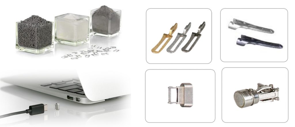
Some well-known 3C electronic application examples for these advanced alloys are camera components (switches and buttons), wearable devices (watch cases), soft magnetic devices, electronic packages, heat sink/ heat spreaders for electronic cooling, laptop hinges and USB connectors, etc.
Significant skill and precision engineering are needed to create the components of the devices noted above, and there are many hurdles to overcome. It is important that product designers can find and select appropriate materials quickly and efficiently to keep up with fast-paced developments.
The attraction of cobalt alloys
Cobalt-base alloys have long been developed for implantable medical devices and have recently been applied to the 3C electronics industry. They exhibit wear-resistant, corrosion-resistant and heat-resistant properties. The most effective use for cobalt-base alloys is in wear-resistant components.
Cobalt is more widely used as an alloying element for heat-resistant applications in nickel-base superalloys, with cobalt tonnages above those used in cobalt-base heat-resistant alloys. Moreover, cobalt-base alloys exhibit excellent resistance to various forms of high-temperature corrosive attack, including oxidation, sulfidation and carburisation reactions.
Many of the commercial cobalt-base alloys that are derived from the Co-Cr-W and Co-Cr-Mo ternaries were first investigated by Elwood Haynes, who discovered the strengthening effect and corrosion resistance imparted to cobalt by chromium in 1907. He later identified tungsten and molybdenum as powerful strengthening agents within the cobalt-chromium system. Co-Cr-Mo alloys, one of the advanced cobalt-base alloys, are widely applied for aircraft engines, medical total hip replacements, dental devices, support structures for heart valves, etc. Co-Cr-Mo alloys are well known for their combination of strong mechanical performance, wear resistance, corrosion resistance and acceptable biocompatibility. However, their main attribute is corrosion resistance in chloride environments.
Besides the previously mentioned applications of Co-Cr-Mo alloys, recently much attention has been paid to their use in the 3C telecommunication industry. For example, smartphone camera bracket components are a promising application for these alloys due to their combination of strength, corrosion resistance, wear performance and non-magnetic properties.

Overview of cobalt alloys
Cobalt-base alloys were introduced to what is now called the superalloy field mainly because of the suitability of the Co-Cr-Mo alloy named ‘Vitallium’ for reproducing complex shapes by precision lost‐wax casting [1]. Many of the properties of the cobalt-base alloys arise from the crystallographic nature of cobalt element. These properties include: the cobalt and solid-solution strengthening effects of chromium, tungsten, and molybdenum; the formation of metal carbides; and the corrosion resistance imparted by chromium. Cobalt-base alloys are strengthened through solid-solution hardening and carbide precipitation hardening by adding carbon, chromium and molybdenum.
Chromium and molybdenum enhance the corrosion resistance of alloys and improve their mechanical properties by reducing abrasive wear and lowering the stacking fault energy. Co-Cr-Mo alloy, an advanced cobalt-base alloy, is widely used in nuclear power plants, aerospace engine vanes and biomedical surgical implants. In the latter case, they are used to make artificial metal-on-metal hip and knee joints. These Co-Cr-Mo alloys are known for their combination of strong mechanical performance, fatigue resistance, low creep, high resistance to wear/corrosion, and biocompatibility, but their main attribute is corrosion resistance in chloride environments. This property is related to their bulk composition (principally the high chromium content) and the formation of a protective surface oxide layer (nominally Cr2O3).
The Co-Cr-Mo alloys have long been widely applied in surgical implants such as joint replacement prostheses (the femoral component in total knee replacement and femoral head in total hip replacement), elbows, fingers, bone plates, screws, rods and dental implants. However, due to cobalt’s classification in many regions as a strategic mineral/metal, global supply shortages and metal price fluctuations might be critical factors for long-term production.
Cobalt-base alloy implants can be conventionally manufactured using wrought or cast techniques. Wrought cobalt alloys are made by forging the material at elevated temperatures under high pressure. Additionally, novel methods for the near-net-shape formation of parts from metal powders via Metal Injection Moulding (MIM) are currently being explored. New applications for MIM components are trending toward smaller, more-complex devices for minimally invasive surgery, especially laparoscopic instruments for grasping tissue, cutting and suturing. Such devices are being designed for greater freedom of movement, which has increased the number of metal components used in the assembly.
MIM has provided the design freedom to produce such components cost-effectively. A new area of exploration for the process is the production of micro-sized components, which should help meet future medical criteria as parts continue to shrink for minimally invasive surgery.
Several ASTM specifications cover material properties for various Co-Cr-Mo compositions and processing routes. The Co-Cr-Mo as-cast alloys conforming to ASTM F75 standards have been widely used for many years to produce surgical implant devices and are still widely used today in many applications such as the femoral component of knee prostheses and the humeral component of shoulder prostheses. A close analogue of this alloy, Stellite 21, was initially used in aircraft turbocharger blades and is still used for wear resistance.
The ASTM F75 Co-Cr-Mo alloy was subsequently modified to make it forgeable, and this advance led to the development of the ASTM specification for Co-28Cr-6Mo alloy forgings for surgical implants (F799). The alloy is available in mill products such as bar stock, which is used either for the direct machining of a device (such as the femoral head of hip prostheses) or its forging (such as cemented hip stems). Before 1994, both bar stock and forgings were covered under ASTM F799. The specification was split in 1994-95 into F799 for forgings and F1537 for bar stock.
Many efforts have been made to improve the mechanical and tribological properties of cast Co-Cr-Mo alloys. There are Co-Cr-Mo alloys available in several different conditions defined primarily by their starting composition (e.g., low or high carbon content) [2], the conditions of manufacture (e.g., casting or forging) [3], subsequent thermal treatments (solution heat treatment, hot isostatic pressing or sintering) [4,5] and engineering surfaces by physical and chemical vapour deposition [6].
The MIM of F75
In the case of F75 produced by MIM, the sintering behaviour of this alloy is of critical importance to obtaining a high-performance product. High sintering temperature in a MIM process is needed to obtain a high sintered density (more than 95% of theoretical) and a homogeneous microstructure. Some of the variables affecting the sintering characteristics of this alloy are the starting particle size, chemistry, porosity and the sintering atmosphere. [7-13].
Within the relatively broad ASTM F75 chemistry specification, it is important to note that minor variations in levels of carbon can lead to significantly different sintering responses and concomitant effects on the density and mechanical properties. Carbides give strength and wear resistance by taking up chromium and molybdenum from the surrounding area during the solidification process. Co-Cr-Mo F75 alloys for mobile phone camera bracket components are one successful commercial MIM application in 3C electronics. There are emerging opportunities for this alloy to be applied in other MIM electronic devices.
Powder metallurgical processes are increasingly deployed to manufacture mechanical components for numerous industrial and consumer applications [14-18]. When suitably compounded with polymeric binder materials, these inorganic powders can be moulded in the same manner as thermoplastics. The products obtained via this process can avoid the density gradient, which is peculiar to the conventional press/sinter process. MIM is most commonly used to make parts with small dimensions, complex shapes, and tight tolerances in high volume. Extrusion or simple compression moulding may be used for parts with simple shapes. Production by MIM brings the shaping advantage of plastic injection moulding but expands the applications to numerous high-performance metals, alloys and technical ceramics.
This advanced technology has grown in popularity in the past three decades as an effective approach to producing geometrically complicated near-net shape parts with accurate dimensions and excellent surface finish. It can make thin-walled parts to tight tolerance in various industries with cost-efficient processes for large-scale manufacturing, such as medical, automotive, aerospace and 3C electronics components [19-37].
Demanding criteria for freedom of geometrical design, sophistication, high-strength, high-volume production capability, fine surface finish, accurate tolerance and flexible materials choice have made MIM thrive in the 3C electronics area. The electronics industry is a major user of metal injection moulded parts, accounting for robust and growing global sales, especially in Asia. Connectors with complex geometries are now the main MIM products. Miniaturisation of electronic devices requires smaller components to achieve better performance at a lower cost. MIM has a competitive advantage for such applications.
Experimental procedure
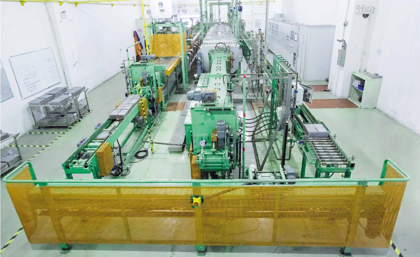
MIM Co-Cr-Mo alloys were prepared via UNEEC’s POM-base feedstocks and using UNEEC mass-production scale continuous furnaces at various atmospheric combinations. Variations in atmospheric combinations led to differences in mechanical properties and microstructures. Neither Hot Isostatic Pressing (HIP) nor heat treatment was applied after sintering.
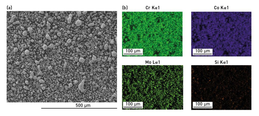
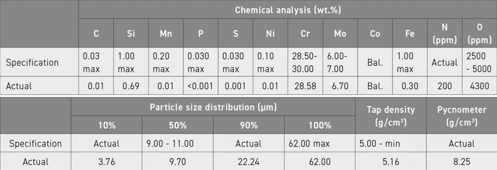
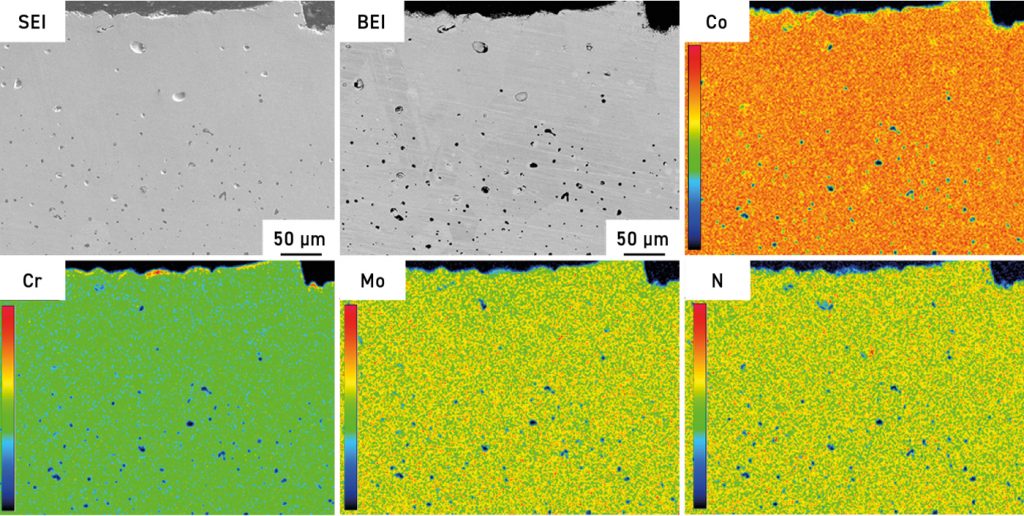
The pre-alloyed Co-Cr-Mo powders used in this study were manufactured by Mitsubishi Steel MFG using its proprietary water atomisation technology. SEM of the powder morphology and major elemental mapping analysis are shown in Fig. 3. Chemical compositions and powder size distribution are summarised in Table 1.
Feedstocks were mixed using UNEEC proprietary multi-component polyoxymethylene-based (POM) binder system via a Z-Blade mixer.
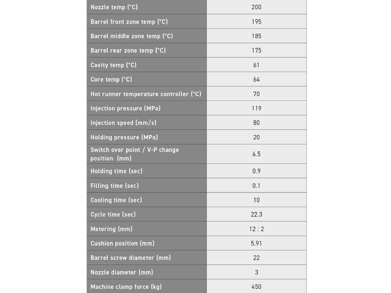
Tensile bar specimens were prepared by injection moulding using a Nissei NEX 50T machine and the injection parameters are summarised in Table 2. Moulded green parts were then subject to a debinding process via a Winteam HT-220LTZL furnace in fuming nitric acid. Various sintering parameter trials were carried out in Cremer Thermoprozessanlagen GmbH walking beam continuous furnaces.
An optical microscope (HM-3006, Jia Yu Apparatus Co., Ltd., Taiwan) was used for morphological examination. X-ray diffraction (XRD) (D2, Bruker, Karlsruhe, Germany) was used for crystal structure identification. Element distribution was assessed via EPMA (JXA-8200SX, JEOL, Japan) with EDS (X-MAX 50, Oxford Instruments, UK). In addition, higher resolution microscopic images and phase investigations were conducted via a Fesem (JSM-7800F Prime, JEOL, Japan) with an electron backscatter diffraction (EBSD) detector (NordlysNano, Oxford Instruments, UK).
Results and discussions
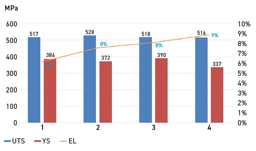
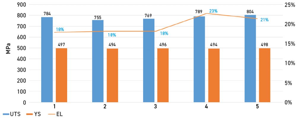
Firstly, the sintering process was conducted in a mixed atmosphere based on the hydrogen to argon ratio at 22:6 m3/h flow rate at 1315°C. Mechanical properties of 4 sintered tensile bars are shown in Fig. 4. This result does not comply with the ASTM F75 standard (UTS ≥ 655 MPa; YS ≥ 455 MPa; Elongation ≥ 8%), owing to inferior UTS and YS performance.
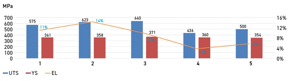
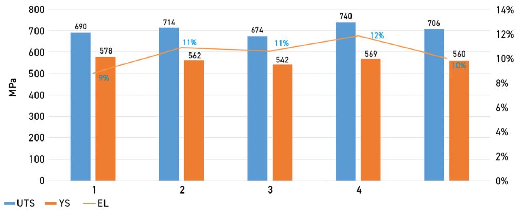
Results for an argon-rich atmosphere (flow rate of hydrogen to argon ratio at 6:22 m3/h at 1315°C) revealed a similar trend of poor mechanical properties, as shown in Fig. 5.
The main goal of this study was to evaluate whether low-carbon grade cobalt alloy feedstocks could achieve the ASTM F75 standard via tuning only sintering parameters/atmosphere, i.e. without applying any post-treatment. Reaching this goal would demonstrate a cost-efficient route for industrial mass production.
Conventionally, MIM sintered compacts’ mechanical strengths could be further enhanced via appropriate post-treatment, such as HIP or solution-annealing heat treatment. Nitrogen (N) solution strengthening is one of the most promising approaches to achieving the aforementioned goal. It is well known that the addition of N to stainless steels stabilises the γ-phase, and high N additions can considerably improve the tensile and fatigue strength of austenitic stainless steels [38-39]. It is also expected that the stability of the γ-phase would be enhanced by N addition in Co-Cr-Mo alloys. Both Fe-Cr and Co-Cr alloy systems have the FCC structure at high temperatures and similar lattice parameters of approximately 0.357 to 0.360 nm [40]. As mentioned in the literature, adding N to the Co-Cr-Mo alloys is a potential strengthening element to change the microstructural characteristics and improve the mechanical properties of alloys [40-42].
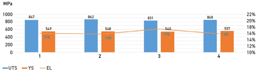
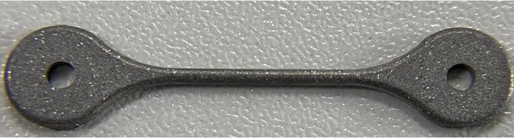
Fig. 6 shows results of the N strengthening approach for a flow rate of hydrogen to nitrogen at 14:14 m3/h at 1315°C. Apparently, mechanical values are significantly improved compared with previous rounds, and this result obviously can reach ASTM F75 standard. However, the sintered alloy’s appearance is black, which is abnormal compared with conventional F75 alloys, as shown in Fig. 7.
An optical microscope analysis was first carried out to investigate this phenomenon further, and the images of the surface region compared with the central core region are presented in Fig. 8.
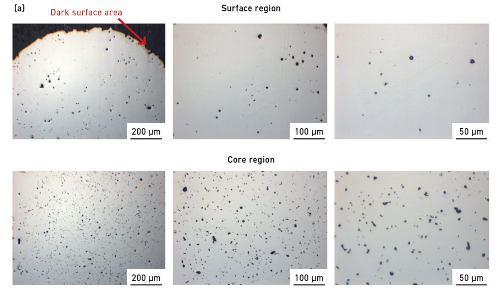
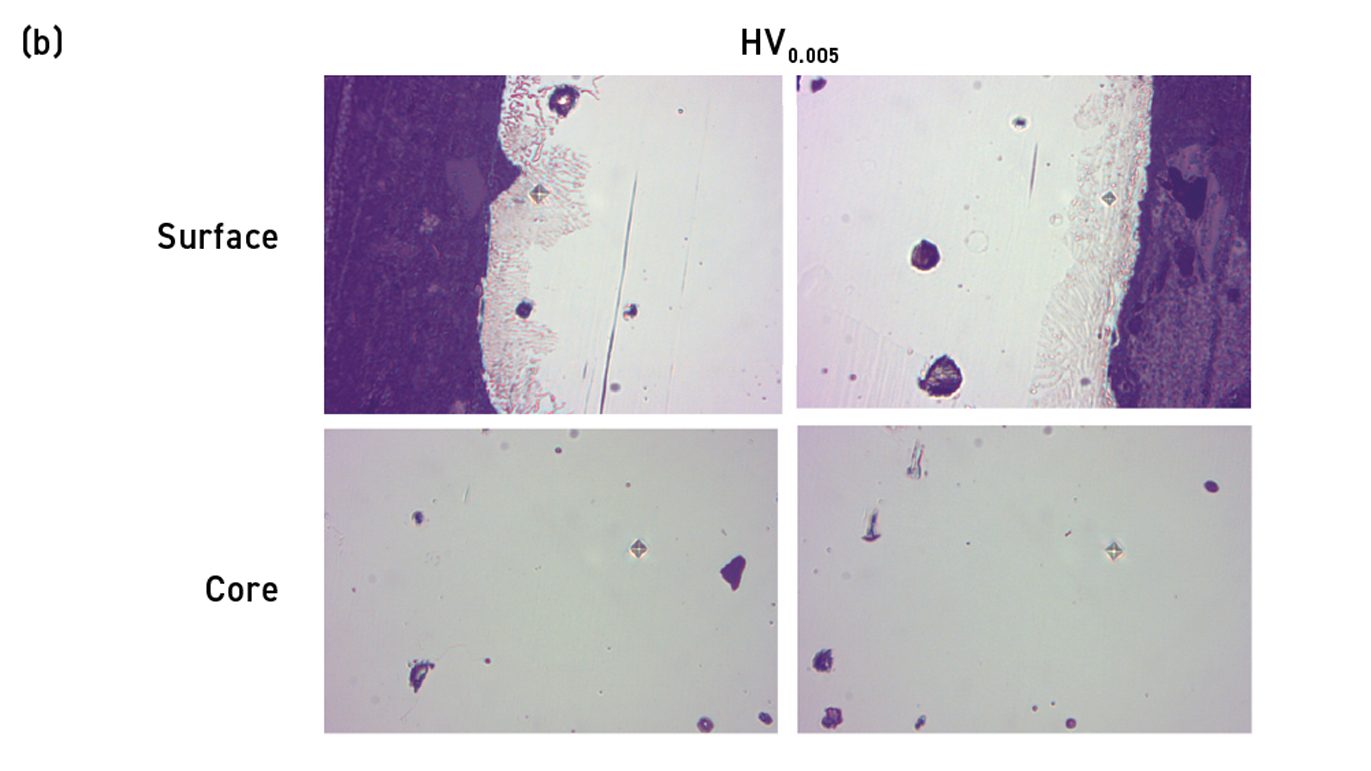
The surface and central core region exhibited microhardness values of 556 HV and 416 HV, respectively. These measurements also implied a difference in microstructure of the surface and central core region and are consistent with the morphologies shown in Fig. 8.
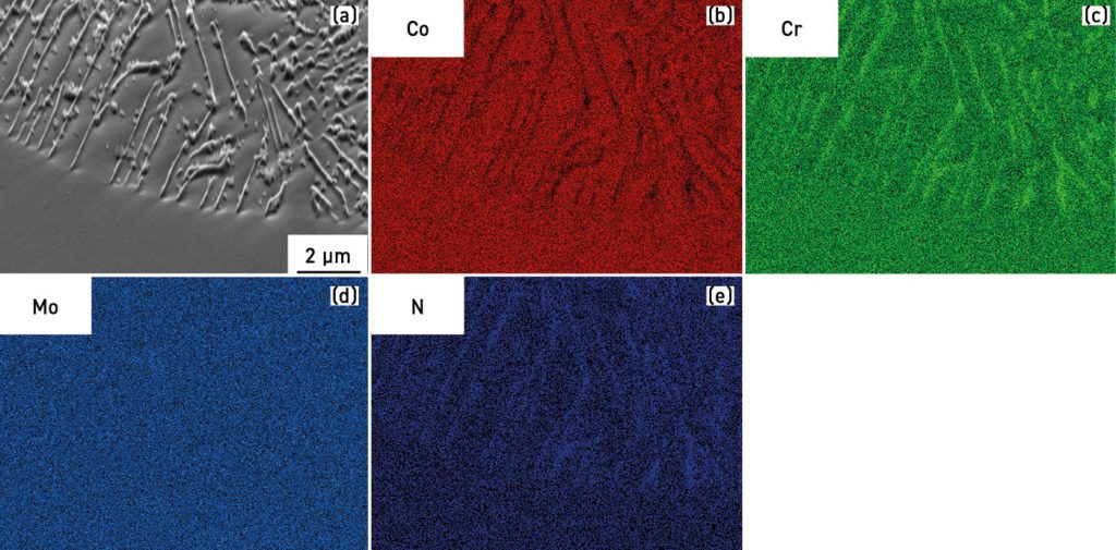
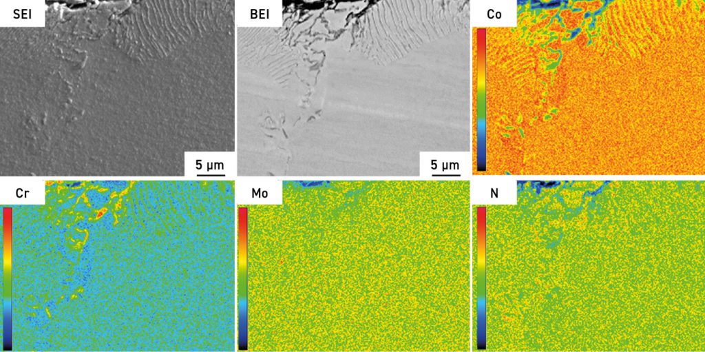
Figs. 9 – 14
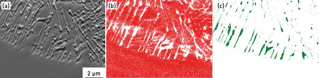
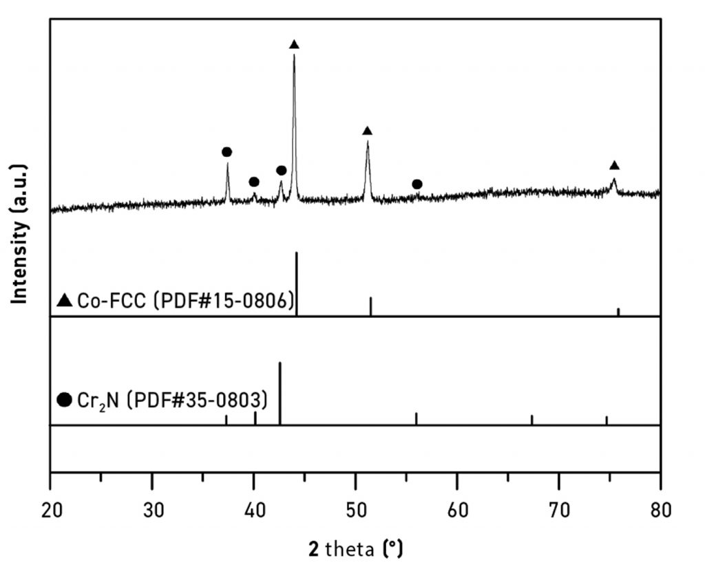
As shown in Figs. 9 – 14, it is obvious that the main matrix of the sintered compact is based on FCC crystal, while some of the Cr2N precipitation existed near the upper surface region, which is in line with the phenomenon reported in the literature [43-44]. Fig. 14 shows the X-ray diffraction patterns for alloys sintered in hydrogen to nitrogen ratio at 14:14 m3/h flow rate at 1315°C. The results indicate that the FCC structure is the predominant phase with a small amount of Cr2N phase in the sintered compact.
From the discussion in previous sections, it is rational to further reduce the nitrogen fraction in the sintering atmosphere to a flow rate of hydrogen to nitrogen ratio at 22:6 m3/h at 1315°C. The effect on the mechanical properties is shown in Fig. 15. Even under this relatively lower nitrogen fraction sintering condition, the UTS, YS and elongation properties still meet the F75 standard. The colour of the sintered alloy is light grey.
This trend in colour transformation implied that the N fraction in the furnace atmosphere plays an important role. It is rational to prevent the Cr2N formation in a sintered compact by an even lower N percentage as a strategy. Therefore, the hydrogen to nitrogen ratio at 25:3 m3/h at 1315°C was selected, with the results shown in Fig. 16. Sintered density is higher than 7.8 g/cm3, and all mechanical properties are in accordance with ASTM F75 standard.
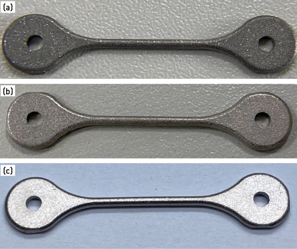
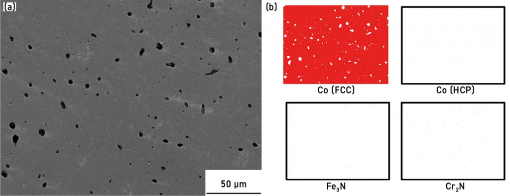
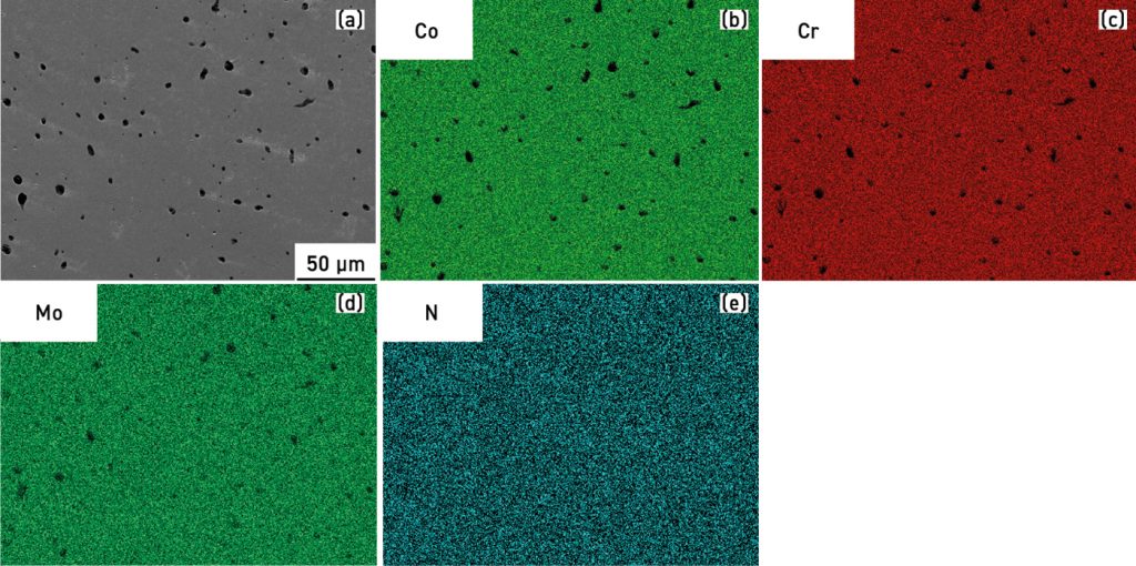
As shown in Fig. 17(a), the dark colour in the sintered specimen is due to Cr2N formation. This trend is less pronounced for the 22:6 atmosphere ratio shown in Fig. 17(b), owing to relatively less precipitation during sintering. The 25:3 atmosphere ratio, shown in Fig. 17(c), exhibited the colour of the conventional Co-Cr-Mo metallic nature. Its corresponding EPMA analysis is shown in Fig. 18, which revealed the absence of Cr2N near the surface region, as estimated, due to the lower nitrogen ratio in the atmosphere.
Conclusions
MIM is a promising method for production of 3C electronic and medical parts with high precision. The experimental results found in this study indicated that Co-Cr-Mo F75 alloys could be made via MIM using POM-based catalytic debinding feedstocks, and could be sintered in large-scale continuous furnaces without requiring post-treatment processes. The sintering atmosphere significantly affects the mechanical properties of Co-Cr-Mo F75 alloys. Various combinations of the sintering atmosphere were explored and discussed in this research. Sintering in a nitrogen-containing atmosphere enhanced the mechanical behaviour of the alloys compared to those sintered in non-nitrogen atmospheric conditions. Sintering in a hydrogen and argon mixed atmosphere led to poor mechanical properties. Optimised sintering conditions are based on a mixed atmosphere of hydrogen to nitrogen ratio as 25:3 in flow rate and conducted at 1315°C. This effect is attributed to nitrogenisation, which compensates for low carbon levels and an increase in strength, while the Cr2N precipitation issue is a function of the relative nitrogen fraction. The microstructure shows a typical F75 FCC crystal. For optimal conditions, all mechanical properties comply with the International Standard ASTM F75. The study’s proposed objectives were achieved. Continuous furnace sintering parameters in this study may not be fully applicable for all MIM cases due to the feedstock chemistry, solid loading, tooling mould geometry, and dimension differences, but these results still serve as a demonstration and reference for the MIM industry.
Authors
Hao-Ming Chen, Yun-Feng Yang, Fan Yang, Chong-Gen Mai, Run-Ming Mai, Zhang-Yi Huang, Dr. Chung-Huei Chueh, I-Shiuan Chen
Advanced Application R&D Dept., R&D Center
Chenming Electronic Technology Corp. (UNEEC), 2F, No. 27, Sec. 6, Minquan E. Rd., Neihu Dist., Taipei City 114, Taiwan
Acknowledgements
The authors gratefully acknowledge colleagues at Chenming Electronic Technology Corp. (UNEEC) and R&D centre for sharing their pearls of wisdom during this research, and for their assistance at every point. Without them this task would not have been possible to accomplish.
Finally, this article is dedicated in memory of Arnold-JiunHung Tsai (蔡駿宏 先生), who passed away in May 2017. Arnold contributed significantly to understanding Powder Injection Moulding binders, feedstocks, tooling mould design, manufacturing, analysis, and R&D innovations. We treasure the memory of his enormous energy, generosity, and selflessness in sharing ideas, contributing towards making PIM a miracle of materials science, and making UNEEC a great company.
Contact
David-ShuHsu Hsieh
[email protected]
Chenming Electronic Technology Corp. (UNEEC), Taiwan
www.uneec.com
References
[1] W. Betteridge: Cobalt and Its Alloys, Ellis Horwood Limited, UK, 1982.
[2] J. Tipper, P. Firkins, E. Ingham, J. Fisher: J Mater Sci Mater Med., 1999, vol. 10, pp. 353-362.
[3] J. Giacchi, C. Morando, O. Fornaro, P. Microstructural: Mater Charact., 2011, vol. 62, pp. 53-61.
[4] H. Mancha, E. Carranza, J. Escalante, G. Mendoza, M. Méndez: Metall Mater Trans., 2001, vol. 32, pp. 979-984.
[5] A. Clemow, B. Daniell: J Biomed Mater Res., 1979, vol. 13, pp. 265-279.
[6] G. Dearnaley: J. Arps: Surf Coat Tech., 2005, vol. 200, pp. 2518-2524.
[7] R. Tandon, in Cobalt‐Base Alloys for Biomedical Applications, ASTM STP 1365, J.A. Disegi, R.L. Kennedy,R. Pilliar eds., West Conshohocken, PA, ASTM, 1999, pp. 3‐10.
[8] T. Kilner, R.M. Pilliar, G.C. Weatherly, C. Allibert: J. Biomedical Mater. Res., 1982, vol. 16, pp. 63-79.
[9] T. Kilner, A.J. Dempsey, R.M. Pilliar, and G.C.Weatherly: J. Mater. Sci., 1987, vol. 22, pp. 565-574.
[10] Y. Koizumi, S. Suzuki, K. Yamanaka, B.S. Lee, K. Sato, Y. Li, S. Kurosu, H. Matsumoto, A. Chiba: Acta Mater.,2013, vol. 61, issue 5, pp. 1648-1661.
[11] W.C. Rodriguez, L. R. Broilo, L. Schaeffer, G. H. Knörnschild, F. H.R. Espinoza: Powder Technol., 2011, vol. 206, issue 3, pp. 233-238.
[12] Sh. Zangeneh, H.R. Lashgari, A. Roshani: Mater. De., 2012, vol. 37, pp. 292-303.
[13] M. Dourandish, D. Godlinski, A. Simchi, V. Firouzdor: Mat Sci Eng A., 2008, vol. 472, pp. 338-346.
[14] S.H. Hsieh, C.H. Chueh, I.S. Chen, M.A. Kearns, P.A. Davies, K. Murray, M-K. Johnston: Powder Inject. Mould. Int., 2018, vol. 12, no. 3, pp. 104-108.
[15] S. Lee, S.H. Hsieh: Powder Inject. Mould. Int., 2019, vol. 13, no. 3, pp. 85-98.
[16] S.H. Hsieh, C.H. Chueh, I.S. Chen, M.A. Kearns, P.A. Davies, K. Murray, M-K. Johnston: Int. J. Powder Metall, 2020, vol. 56, no. 1, pp. 41-49.
[17] S.H. Hsieh, C.H. Chueh, I.S. Chen, M.A. Kearns, P.A. Davies, K. Murray, M-K. Johnston, S. Kubal: Powder Inject. Mould. Int., 2020, vol. 14, no. 1, pp. 81-93.
[18] S.H. Hsieh, C.H. Chueh, I.S. Chen : Powder Inject. Mould. Int., 2021, vol. 15, no. 4, pp. 105-121.
[19] R.M. German: Int. J. Powder Metall., 1987, vol. 24, no. 3, pp. 237-245.
[20] M.J. Cima, J.A. Lewis, A.D. Devoe: J. Am. Ceram. Soc., 1989, vol. 72, no. 7, pp. 1192-1199.
[21] H.M. Shaw, M.J. Edirisinghe: Am. Ceram. Soc. Bull., 1993, vol. 72, no. 9, pp. 94-99.
[22] C. Dong, H.K. Bowen: J. Am. Ceram. Soc., 1989, vol. 72, no. 6, pp. 1082-1087.
[23] P. Calvert, M. Cima: J. Am. Ceram. Soc., 1990, vol. 73, no. 3, pp. 575-579.
[24] M.R. Barone, J.C. Ulicny: J. Am. Ceram. Soc., 1990, vol. 73, no. 11, pp. 3323-3333.
[25] H.H. Angermann, O.O.V.D. Biest: Int. J. Powder Metall., 1993, vol. 29, no. 3, pp. 239-250.
[26] S.A. Matar, M.J. Edirisinghe, J.R.G. Evans, E.H. Twizell: Int. J. Powder Metall., 1987, vol. 23, no. 4, pp. 237-245.
[27] E.S. Thian, N.H. Loh,K.A. Khor, S.B. Tor: Adv Powder Technol., 2001, vol. 12, no. 3, pp. 361-370.
[28] S. Masia, P.D. Calvert, W.E. Rhine, H.K. Bowen: J. Mater. Sci., 1989, vol. 24, no. 6, pp. 1907–1912.
[29] F.Q. Nogueira, M.J. Edirisinghe, D.T. Gawne: J. Mater. Sci., 1992, vol. 27, no. 23, pp. 6525-6531.
[30] J.K. Wright, J.R.G. Evans, M.J. Edirisinghe: J. Am. Ceram. Soc., 1989, vol. 72, no. 10, pp. 1822-1828.
[31] M.J. Edirisinghe: J. Mater. Sci. Lett., 1991, vol. 10, no. 22, pp. 1338-1341.
[32] R.M. German, K.F. Hens: Ceram. Bull., 1991, vol. 70, no. 8, pp. 1294-1302.
[33] R.M. German: Powder Metall. Int., 1993, vol. 25, no. 4, pp. 165-169.
[34] K.M. Kulkarni: Met. Powder Rep., 2000, vol. 55, no. 10, pp. 40-42.
[35] C. Ballard, M. Zedalis: Advances in powder injection molding, in: Annual Technical Conference–ANTEC, Conference Proceedings, 1998, vol. 1, pp. 358-361.
[36] A. Hauck: Int. J. Powder Metall., 2000, vol. 36, no. 3, pp. 29-30.
[37] R.M. German: Int. J. Powder Metall., 2000, vol. 36, no. 3, pp. 31-36.
[38] J. Menzel, W. Kirschner ,G. Stein: ISIJ Inter., 1996, vol. 36, pp. 893–900.
[39] M. B. Horovitz, F. B. Neto, A. Garbogini, A. P. Tschiptschin: ISIJ Inter., 1996, vol. 36, pp. 840–845.
[40] T. Kilner, A. Dempsey, R. M. Pilliar , G. C. Weatherly: J. Mater. Sci., 1987, vol. 22, pp. 565-574.
[41] A.J. Dempsey, R.M. Pilliar, G.C. Weatherly, T. Kilner: J. Mater. Sci., 1987, vol. 22, pp. 575-581.
[42] J. Escobedo, J. Méndez, D. Cortés, J. Gómez, M. Méndez, H. Mancha: Mater. Des., 1996, vol. 17, no. 2, pp. 79-83.
[43] S. Mineta, N.S. Alfirano, T. Yoneda, K. Ueda, T. Narushima : Metall Mater Trans A., 2013, vol. 44, pp. 494-503.
[44] T. Kilner, A.J. Dempsey, R.M. Pilliar, G.C. Weatherly: J. Mater. Sci., 1987, vol. 22, pp. 565-574.