


A microstructural investigation of 420 martensitic stainless steel processed by Metal Injection Molding
Type 420 martensitic stainless steel covers a wide carbon range of 0.15% to 0.45%. Demand for this material from the 3C, automotive, biomedical and aerospace industries has been increasing thanks to its combination of moderate corrosion resistance, high hardness, and good tensile properties. In this study, Shu-Hsu Hsieh, Dr Chung-Huei Chueh, and I-Shiuan Chen, from Chenming Electronic Technology Corp. (UNEEC), Taiwan, investigated Nb-alloyed 420 produced using BASF SE's Catamold 420 W feedstock. Decarburisation was examined in samples processed in both a graphite furnace and a molybdenum lined furnace. Microstructure, phase and hardness variations from the sintered state to each specific stage in heat treatment were also explored. Additionally, the influence of niobium on the formation of intergranular compounds, carbides, and carbonitrides was also assessed in each heat treatment stage for comparison. [First published in PIM International Vol. 15 No. 4, Dec 2021 | 35 minute read | View on Issuu | Download PDF]
Among the most exciting emerging developments in the modern 3C (computer, communication and consumer-electronics) industry are applications based on advanced metallic materials. These new applications take advantage of materials with excellent mechanical strength combined with reasonably high corrosion resistance, wear resistance and specific magnetic properties, such as ferromagnetism or paramagnetism, depending on the product design and function. These materials include stainless steels and cobalt alloys, as well as other cutting-edge alloys.
Some well-known examples for these advanced alloys are camera components (switches and buttons), laptop and smartphone hinges, cases for wearable devices, soft magnetic applications, electronic packaging, heat sinks/heat spreaders for cooling electronics, and USB connectors. A high degree of skill and precision engineering is needed to create the components that go into such devices and there are many hurdles to overcome. It is, however, important that product designers in this field are able to find and select the proper materials quickly and easily in order to keep on top of the fast-paced development.
Stainless steels, a group of advanced ferrous alloys, were invented at the beginning of the 20th century in Germany (Eduard Maurer and Benno Strauss in 1912) and in England (Harry Brearley in 1913). In accordance with the European standard EN 10088, steel is classed as stainless when its chemical composition has a minimum chromium content of 10.5%, which enables the formation of a thin, tenacious, and protective chromium oxide passive film. Stainless steels can be ferritic, austenitic, martensitic or a combination of all phases, according to their chemical composition.

Martensitic stainless steels (MSSs), formed via diffusionless transformation, are a class of stainless steels with hardenability, meaning that the mechanical properties of the steels can be significantly altered by a hardening heat treatment to achieve the desired mechanical properties, such as superior strength, high hardness and high toughness, etc. This type of steel is characterised by a limited chromium content (normally between 11.5% and 18%) and carbon contents among the highest of the stainless steels most commonly used (generally between 0.1% and 1%, C<0.015% for the supermartensitic grades), as can be observed in a conventional Schaeffler diagram. MSS type 410 is a grade that is regarded as a general purpose martensitic steel and contains about 12 wt.% Cr and 0.1 wt.% C to provide strength.
Applications for type 410 include fasteners, springs, pins, cutlery, hardware, gun clips, microparts, turbine blades, coal screens, pump rods, nuts, bolts, fittings, ball bearings, shafts, impellers, pistons, and valves. The carbon level – and consequently, strength – increase in the 420, 440A, 440B, and 440C alloy series. MSS type 420 covers a wide carbon range of 0.15% to 0.5%, the selected carbon content depending on the desired hardness, and therefore has a relatively wide range of hardness levels in both the hardened and tempered conditions.

Higher carbon leads to increased hardness at the expense of ductility and corrosion performance. Versatile hardness can be obtained via heat treatment cycles, and this makes type 420 desirable where tempered products are necessary for specific applications, such as laptop/smartphone hinges, steam generators, mixer blades, fasteners, cutlery, machine parts, bushings, surgical tools, firearms, needle valves and ball valves. 440A, 440B, and 440C, in particular, have an increased Cr level in order to maintain corrosion resistance.
In general, 440A has excellent hardening performance and high hardness, and its toughness is higher than that of 440B and 440C. 440C stainless steel is a member of the 400 series of stainless steels. It has the highest carbon content among them. The standout properties of this type of steel are its hardness, mechanical strength and fatigue resistance, making it useful in the production of cutting tools. Due to 440C’s high carbon content, it does not have outstanding corrosion resistance, but it can still be used for applications that require moderate corrosion resistance such as surgical instruments, cutting tools, nozzles and bearings. 440C steel is sometimes called ‘surgical stainless’.
Alloying elements, like Mo, Ni, V, Nb, Al and Cu, are added for the enhancement of specific properties. Molybdenum can be added to enhance mechanical properties or corrosion resistance, as it is in type 422 stainless steel. Nickel can be added for the same reason in type 414 and 431. When higher Cr levels are designed to improve corrosion resistance, nickel also serves to stabilise the desired microstructure and to prevent excessive free ferrite. The limitations on the alloy content required to maintain the desired fully martensitic structure restrict the obtainable corrosion resistance to moderate levels. Chromium, a high ferrite stabilising element, and carbon, an austenite stabilising element, are balanced so that the steel has an austenitic structure at high temperature and a martensitic structure at ambient temperatures.

One of the benefits of martensitic steel is that it becomes stronger and harder after heat treatment. Heat treatment is the controlled heating and cooling operation performed on the material. When the material is subjected to heat treatment, the atomic structure or microstructure may change due to movement of dislocations, increase or decrease in solubility of atoms, increase in grain size, formation of new grains, creation of new different phase and change in crystal structure [1-12].
The typical heat treatment process for martensitic stainless steels such as 420 includes heating to the soft-annealed condition, where islands of spherical carbides exist in a ferritic matrix, resulting in a soft steel which allows subsequent cold work or machining. Moreover, a subsequent austenitising treatment forms an austenitic structure and fully or partially dissolved carbides, cooling or quenching to transform the austenite to martensite, followed by tempering of the martensitic structure to improve toughness and ductility.
During the transformation of FCC γ- phase (austenite) into a BCC lattice structure, after reaching the critical cooling rate that is high enough to suppress the solid-state diffusion of dissolved carbon atoms, the lattice structure is deformed and the nucleation of a martensite grain grows rapidly through the material until it approaches another grain boundary. When the cooling rate is fast enough, the dissolved carbon in the austenite cannot diffuse out of the FCC lattice structure, leading to a tetragonal lattice distortion (i.e., BCT, or body-centered tetragonal, crystal structure). As for cryogenic treatments [13-25], normally carryied out after a conventional quench process but before tempering, these are usually carried out at -80°C and -196°C, corresponding to dry ice sublimation temperature and liquid nitrogen boiling temperature, respectively.
When heat-treated steels are cooled to extremely cold temperatures, retained austenite is transformed to martensite. Retained austenite is brittle and, if not transformed to martensite, can cause chipping or cracking. As a worst case, retained austenite can act as nucleation sites for metal fatigue. In order to increase ductility and toughness, martensite is heat treated in a process called tempering. Strength typically decreases with increasing tempering temperature and time and a corresponding increase in toughness is expected.
Heat treating martensitic stainless steels is essential to achieve improved strength, fracture toughness and hardness, depending on carbon content. The final microstructure of AISI 420 is very dependent on the prior heat treatment that the steel receives and typically consists of martensite, undissolved and/or re-precipitated carbides and retained austenite. The volume fraction and size of the carbide particles present in the steel and the amount of retained austenite play a major role in determining the hardness, strength, toughness, corrosion resistance, and wear resistance of the steel.
Powder metallurgical processes are increasingly deployed for the manufacture of mechanical parts for numerous industrial and consumer applications. When suitably compounded with polymeric binder materials, these inorganic powders can be moulded in the same manner as thermoplastics. The most common example of this approach is Metal Injection Moulding for small parts with high shape complexity, tight tolerances, and high production volumes. For parts with simple shapes, extrusion or simple compression moulding may be used.
The products obtained via this process can avoid the density gradient that occurs in the conventional ‘press & sinter’ Powder Metallurgy process. MIM uses the shaping advantage of plastic injection moulding, but expands the applications to numerous high performance metals and alloys. This advanced technology has grown in popularity in the past three decades as an effective approach to producing geometrically complicated near-net shape parts, with high dimensional accuracy and excellent surface finish, and it can make thin-walled parts to tight tolerances for a variety of industries using a process that is extremely cost-competitive for large scale production. Major markets for MIM include medical, automotive and aerospace, as well as the 3C sector previously mentioned [26-44].
The high level of freedom when designing geometrically, sophisticated, high-strength, high-volume production parts, with a fine surface finish, accurate tolerance, and flexible material choice has enabled MIM to thrive in the 3C area. The electronics industry is a major user of MIM parts, accounting for robust sales growth globally, but especially in Asia. Connectors with complex geometries are now major MIM products and the continuing miniaturisation of electronic devices demands ever smaller components in order to achieve better performance at lower cost. This is where MIM has a unique competitive advantage.
In this article, Nb-modified 420 was prepared via the MIM process and its microstructures, phases, and precipitates were investigated. Decarburisation was investigated in a graphite furnace and a molybdenum lined furnace, respectively. Hardness and microstructure in each specific stage of heat treatment were also examined and assessed.
Experimental procedure
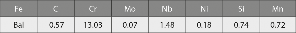
The feedstock used in this study, Catamold 420 W, was manufactured by BASF using its proprietary polyoxyethylene-based (POM) binder system. This is based on Nb-modified type 420 martensitic stainless steel powder and the composition is shown in Table 1.
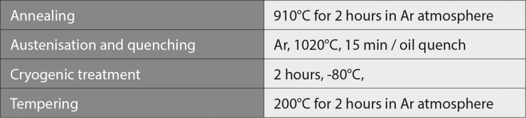
Green parts were prepared by injection moulding under various conditions using a NISSEI NEX 50T machine. Moulded parts were then subject to a debinding process in a WINTEAM HT-220LTZL furnace in fuming nitric acid. Sintering trials were first performed in a SHIMADZU VHSgr 40/40/150-M graphite batch furnace using argon atmosphere at 60 kPa pressure. For comparison, sintering was also conducted in a Nabertherm VHT 40/16-MO H2 molybdenum lined furnace in flowing nitrogen at 100 kPa pressure, at 1340°C for 3 hours with 5 K/min heating rate. The conditions chosen for heat treatment are given in Table 2.
X-ray diffraction, XRD, (D2, Bruker, Karlsruhe, Germany) was applied for crystal structure identification. Element distribution was assessed via EPMA (JXA-8200SX, JEOL, Japan) with EDS (X-MAX 50, Oxford Instruments, UK). For morphological, microscopic and phase investigations, Optical Microscope (HM-3006, Jia Yu Apparatus Co., Ltd., Taiwan) and FESEM (JSM-7800F Prime, JEOL, Japan) with electron backscatter diffraction (EBSD) detector (NordlysNano, Oxford Instruments, UK) were applied. Transmission Electron Microscope, TEM (JEM-2100F, JEOL, Japan), with EDS (INCA X-sight, OXFORD, UK) was also applied.
Results
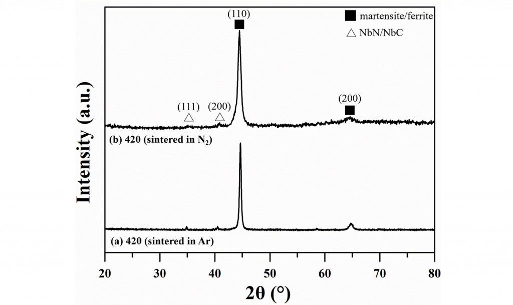
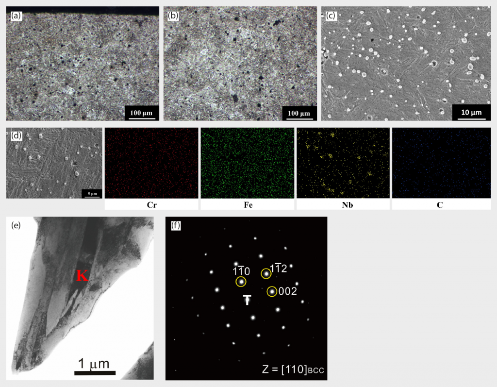
The XRD patterns of Ar-sintered 420 W are shown in Fig. 2 (a). The major crystal structure is BCT martensite or BCC ferrite, since these two crystal structures are indistinguishable in XRD due to having quite similar lattice constants. The optical microscopy (OM) images of Ar-sintered 420 W surface and central regions are shown in Fig. 3 (a) and (b), respectively. From the OM results, martensite is the major structure and thus the presence of BCC ferrite can be excluded in the XRD results in Fig. 2 (a). From OM images, it can be clearly observed that a roughly 100 μm to 150 μm thickness of decarburisation white-layer appeared near the upper side of the surface region.
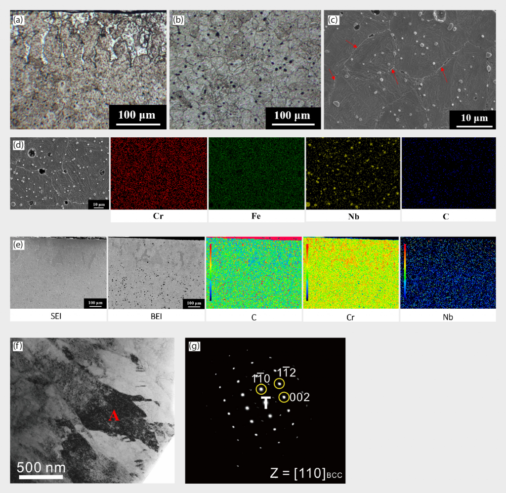
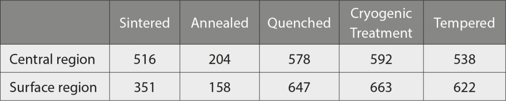
Utilising EPMA mapping in Fig. 3 (e) also revealed the presence of low-carbon and high-chromium concentration areas, confirming the decarburisation phenomenon aforementioned. For the central region, the microstructure is identified as martensite, as shown in Fig. 3 (c), (f), and (g), and there is a significant amount of precipitated particles, both on grain boundaries (intergranular compound, highlighted by the red arrow) as well as inside the grains, shown in Fig. 3 (c). The precipitated particles are abundant in Nb and C, as demonstrated in EDS elemental mapping in Fig. 3 (d). Table 3 also points out the hardness deviation between the surface and central regions of sintered specimens. The surface region has lower hardness than the central region, implying that the presence of ferrite white layer led to the hardness reduction, while the central region structure is still based on a high hardness martensite matrix.
Commercial martensitic stainless steels are often supplied in the annealed state, allowing the material to be easily formed and machined by the fabricator or user. Annealing is recognised as the procedure whereby a material is heated to and held at a suitable temperature and then cooled at a well-defined rate to reduce hardness, improve machinability, facilitate cold workability, produce a specific microstructure, or obtain desired mechanical, physical or other properties
In this work, the annealing process was conducted at 910°C for 2 hours in Ar atmosphere. The OM images of the annealed 420 W surface and central regions are shown in Fig. 4 (a) and (b), respectively. Decarburisation white layers of 100 μm to 150 μm thickness near the surface region are still observed, implying that the annealing treatment cannot effectively eliminate this white layer. EPMA mapping was also applied to confirm this phenomenon, in Fig. 4 (e), indicating lower carbon concentration in this decarburisation white layer.
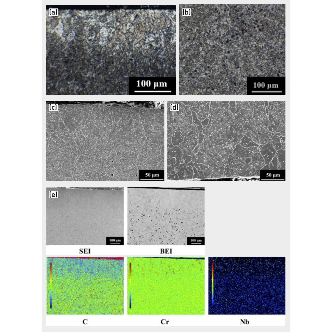
As for the FESEM microstructure, the whole specimen is transformed from a martensitic matrix to a α-ferrite matrix in this heat treatment condition, as shown in Fig. 4 (c) and (d), which also corresponds with the hardness result in Table 3, since ferrite structure is soft and substantially low in hardness. Intergranular compounds are still visible, and some small particles (less than 0.5 μm in size) are formed inside the grains, as shown in Fig. 4 (c) and (d).
After annealing, a subsequent austenisation and quenching heat treatment was applied. This hardening treatment, specified for martensitic stainless steels, typically consists of heating to a temperature high enough to ensure an FCC austenitic structure with carbon in solid solution, followed by rapid cooling (air cooling or oil quenching) to form martensite at room temperature. Air cooling of a fully austenitic structure usually produces full hardening in type 420, but oil quenching is utilised for larger sections to ensure complete transformation to martensite. An undesirable complication of type 420 is the tendency to retain austenite (RA) after quenching.
The presence of significant amounts of retained austenite reduces the as-quenched hardness of the alloy and may promote embrittlement, if fresh, untempered martensite forms during tempering. Multiple tempering steps can be used to temper the fresh martensite, or cryogenic (sub-zero) treatment can be used to reduce the retained austenite content prior to tempering. For the quenched specimen prepared, the surface and central regions both have a martensite matrix structure with some particles, shown in Fig. 5 (a)-(c). The surface cooling rate is higher than that of the central region during the quenching step; thus, this caused a relatively higher hardness at the surface, as indicated in Table 3.
Intergranular compounds seem to be dissolved in this state, due to the rapid cooling rate via oil quenching to suppress the formation of this compound. Moreover, small particles are still abundantly dispersed, due to the austenisation temperature of 1020°C possibly not being high enough to completely dissolve the particles in the austenite phase. Increasing the austenisation temperature typically enhances carbide dissolution and increases the solubility of alloying elements in the austenite, but also leads to grain coarsening and reduces the martensitic transformation, thereby increasing the volume fraction of retained austenite. The decarburisation white layer seems to be eliminated in this stage and the carbon concentration profile is uniform in EPMA mapping, shown in Fig. 5 (d). This is due to the heating to high temperature in austenisation step being able to provide sufficient energy and time for carbon to diffuse from the inner region (with higher concentration) to the carbon-deficient decarburisation white layer and, thus, in turn it makes the carbon concentration uniformly distributed across the whole specimen.
The precipitated particles are abundant in Nb and C, as shown in EDS mapping in Fig. 5 (e). In EBSD phase identification in Fig. 5 (f), BCT martensite matrix and NbC particles are the major microstructural features in the quenched state. BCT and BCC lattice structures are indistinguishable in EBSD due to their similar lattice constants, but BCC structure can be excluded on the basis of OM morphologies. A TEM image of martensite and its electron diffraction patterns are shown in Fig.5 (g) and (h), respectively and are consistent with EBSD results. The selected area ‘D’ in Fig. 5 (g) and (h) is a single martensite lath. Some retained austenite could be detected in Fig. 5 (i), as electron diffraction patterns of austenite, and Fig. 5 (j) TEM dark field image, respectively. The DE circle indicates that the D and E two laths were simultaneously selected and analysed using selected area diffraction. Retained austenite is normally observed within martensite laths. Particles with NbC structure were also verified, as shown in Fig. 5 (k) and (l), also being consistent with EBSD results Fig. 5 (f).
The presence of retained austenite is problematic for many applications because, among other effects, it reduces the dimensional stability of steel components. The fraction of retained austenite should consequently be reduced as much as possible. Cryogenic treatment is the supplement for the conventional heat treatment process, in which materials are subjected to very low temperatures, to enhance the mechanical properties of the material being treated. This treatment is done after quenching and before the tempering of steel [45-46]. Various advantages, such as improved wear resistance, reduced residual stress, increase in hardness, dimensional stability, fatigue resistance, toughness by transformation of retained austenite into martensite and precipitation of ultrafine carbides [47-50] were noted. In this study, cryogenic treatment was conducted at -80°C for 2 hours to assist some retained austenite being further transformed to martensite. The morphologies from Fig. 6 (a)-(c) are almost similar to the images obtained from the quenched state, martensite as the major matrix with disperse NbC precipitates.

Phase identification from EBSD phase mapping is shown in Fig. 6 (e) and reveals that a BCT martensite matrix and NbC precipitates are the major microstructural features in this condition. EBSD image quality (IQ) maps were shown in Fig. 6 (f) and these can clearly identify each martensites lath’s boundary. Boundaries with misorientations from 2° to 62° are demonstrated in Fig. 6 (h) and, from this, the prior austenite grain (PAG) boundary could be clearly depicted by the red line. From TEM morphologies in Fig. 6 (i) and selected area ‘J1’ diffraction patterns in Fig. 6 (j), the structure was identified as martensite. The diffraction spots marked by the yellow and blue circles belonged to two martensite grains.
The last process in heat treatment is tempering. In the ‘as-quenched’ or ‘sub-zero treatment’ martensitic condition, the steel is hard and brittle and may contain pockets of retained austenite. Quenching is therefore followed by tempering to reduce brittleness, increase ductility/toughness and reduce residual stresses. The presence of residual stress could obviously be deleterious to the mechanical and corrosion properties. A good combination of toughness and strength is then achieved. In the case of type 420, tempering is performed at a low temperature (below 400°C).
Great care is taken to prevent the tempering process from taking place within the temperature range of 450°C to 600°C: this interval is considered critical as it reduces resistance to brittle fracture and significantly reduces corrosion resistance. The 200°C tempering treatment results from Fig. 7 are quite similar to the quenched and cryogenic treatment states in microstructure, a major phase of martensite and dispersed particles, since tempering at 200°C may not induce microstructural change, such as carbide coarsening or carbide precipitation. Only the stresses induced due to the hardening operation will be relieved via this low temperature 200°C tempering treatment.
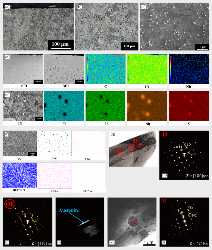
In general, graphite insulation is more likely to absorb moisture than metal insulation in furnace systems and this might be the potential root cause for the decarburisation occurring in previous discussion. Based on this, a molybdenum lined furnace was also used in this research for comparison. As shown in Fig. 8 (a) to (d), from surface to central regions are martensite matrice without the presence of a decarburisation layer. EBSD results in Fig. 8 (e) and (f) also confirmed the martensite BCT structure and the dispersed particles as being NbN. EBSD image quality (IQ) maps were shown in Fig. 8 (g), which can clearly identify each martensite lath’s boundary. Boundaries with misorientations from 2° to 62°are demonstrated in Fig. 8 (i) and, from this, the prior austenite grain (PAG) boundary could be clearly depicted by the red line. TEM images and diffraction patterns also verified the BCT martensite and NbN structure from Fig. 8 (j) to (l). The XRD analysis in Fig. 2 (b) implies martensite matrix as the major microstructure, which is consistent with OM, EBSD and TEM results aforementioned.
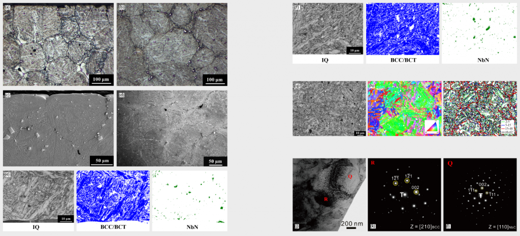
(g) EBSD image quality (IQ) maps of central region (h) BCC/BCT crystal orientation mapping of Fig. 8 (g) IQ maps
(i) Boundaries with misorientation from 2° to 62° of Fig. 8 (g) IQ maps (j) TEM image of surface region (k) Electron diffraction patterns of TEM image above, selected area “R” (l) Electron diffraction patterns of TEM image above, selected area “Q”
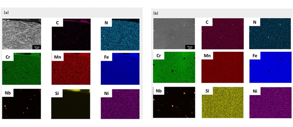
EDS mapping results from Fig. 9 (a) and (b) revealed that the spherical particles are abundant in Nb, Cr and N. The carbon distribution in Fig. 9 (a) is uniform and none of the deficient (decarburisation) area is observed. EPMA mapping results from Fig. 10 (a) and (b) are consistent with the EDS analysis results.
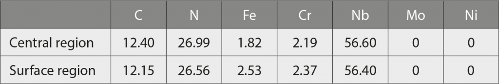
From Table 4, the EPMA quantitative analysis results also verified the precipitated particles as containing the major C, N, and Nb elements. Combining the results from XRD, EBSD and EPMA, the structures of the precipitated particles are ‘carbo-nitride’ based compound and the exact structure is Nb (C,N).
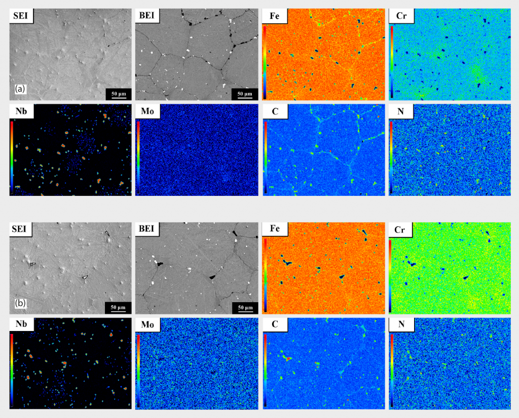
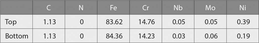
Table 5 shows that almost no N or Nb are detected in the martensitic matrix from the top to the bottom area of the sintered specimen, due to the low solubility of nitrogen in martensitic matrix. Based on the results from Table 4 and Table 5, nitrogen atoms are effectively diffusing into the 420 W sintered sample, but most of nitrogen atoms are forming carbo-nitride Nb (C,N) particles, rather than dissolving in the martensitic matrix, owing to the limited solubility of nitrogen in martensite aforementioned. Also, Nb is a strong carbide and nitride former (with affinity towards nitrogen being higher than for Cr) [51]. Consequently, type 420 is able to keep an effective content of chromium in the matrix, which will be beneficial for corrosion resistance
Discussion
Decarburisation is recognised as the loss of carbon atoms from the surface of ferrous materials producing a carbon concentration gradient across a short distance below the surface. This is a serious problem as the weaker surface layer reduces wear resistance, enabling fatigue failures to occur more easily. This occurs when carbon atoms at the ferrous material’s surface interact with the oxygen, metal oxide or moisture in the atmosphere when it is heated at 600°C or above, where the driving force is the carbon chemical potential across the material and the atmosphere [52–70].
Carbon from the interior diffuses towards the surface, moving from high to low concentration and continues until the maximum depth of decarburisation is established. Concerning the loss of carbon in sintering, a continuous layer of soft ferrite is being produced together with ferrite formation around austenite grains and this ferrite structure is maintained on cooling to room temperature due to insufficient hardenability (carbon is a key element inenhancing hardenability).
Apart from these areas, austenite will subsequently transform to a martensitic structure in the cooling stage. Hence, the final structure in the decarburisation layer is based on a ferrite and martensite mixed structure. In this work, decarburisation is obvious at the upper surface region in sintered specimen based on the graphite furnace system and this lead the hardness variance between the surface and central regions. In general, graphite insulation is more likely to absorb moisture than metal insulation and this could explain the presence of the decarburisation white layer in the graphite furnace system, but it’s not being observed in the metal furnace system.
The surface hardness in the as-sintered state is lower than the standard type 420 value, but can be improved via high temperature austenitisation diffusion in the heat treatment procedures, as shown in Table 3. Carbon atoms are thus distributed homogeneously from the central region to the upper surface. During the austenitisation stage, an excess amount of carbon is dissolved and then cooled rapidly to form ‘supersaturation’ martensite. This supersaturation martensite has a higher extent of lattice distortion, compared with the as-sintered state, and is revealed from the hardness variance in Table 3.
However, 420 W has quite a high carbon content and seems not to be easy to dissolve totally in the supersaturation state; hence, remaining undissolved carbon is precipitated in the form of NbC particles. In the subsequent cryogenic treatment, some remaining retained austenite (RA) is further transformed to martensite to enhance overall hardness, but the increment is limited due to the low RA volume fraction. In the final step, tempering caused some degree of hardness reduction as expected, for improving ductility and toughness. For the morphologies from the quenched to the tempered state, the matrices are all martensite, differing only in hardness.
Upon furnace cooling after sintering, there will be sufficient time for diffusion to form compounds, especially near the grain boundary region, due to the lowest activation energy for forming compounds in this boundary. Hence, for slow cooling rates, having sufficient time during sintering, intergranular compounds are observed. The subsequent annealing state’s morphology revealed a similar intergranular compound distribution to sintered state due to a similar slow cooling. However, in the subsequent quenched and cryogenic treatment state, those intergranular compounds are dissolved, due to the high cooling rate. From a mechanical point of view, intergranular compounds are deleterious to strength [71-80] and, therefore, the dissolving of intergranular compounds via heat treatment in this study is beneficial to a specimen’s overall mechanical strength.
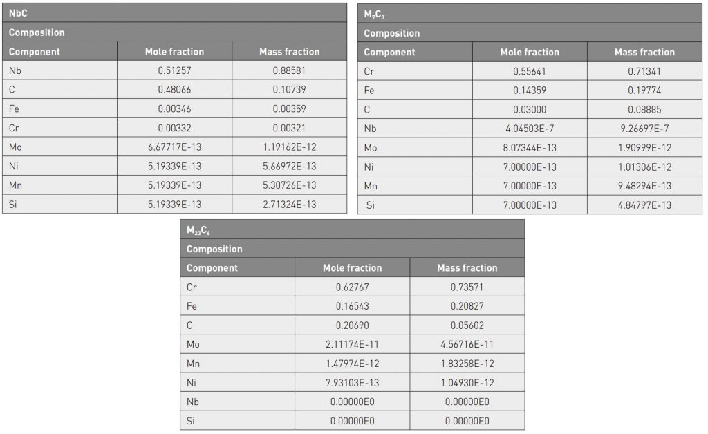
In this research, the MIM 420 powder composition is modified by adding niobium, to stabilise carbon via the forming of niobium carbide (graphite furnace system) and niobium carbo-nitride Nb(C,N) in the molybdenum lined furnace, which results in inhibiting the formation of chromium carbides, such as Cr23C6 and Cr7C3. These chromium carbides are well known to lead to the sensitization phenomenon. Consequently, type 420 is able to keep an effective content of chromium in the matrix, which will be beneficial for corrosion resistance.
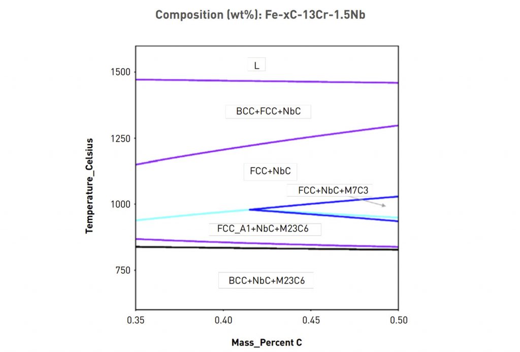
Fig. 11 shows a pseudo-binary Fe-Cr-Nb-C phase diagram calculated by Thermo-Calc software for the Nb-modified 420 stainless steel. From this diagram, it is predicted that the only stable carbide existing above 1000°C will be NbC and this prediction is entirely consistent with the XRD, EBSD and TEM results. According to the simulated phase diagram, it can be inferred that NbC is a relatively stable carbide in the Nb-modified 420 stainless steel. Therefore, NbC particles can be clearly observed even after annealing at 910°C or oil quenching from 1020°C. Since thermodynamic simulation software is normally used to calculate various properties in an equilibrium state, the experimental results obtained for a non-equilibrium state did not coincide with those simulated with Thermo-Calc software [81].
Conclusions
Martensitic stainless steel 420 samples were prepared using the MIM process. A graphite furnace and a molybdenum lined furnace were used for surface microstructure comparison and this study confirms that decarburisation occurred only in the graphite furnace system because of its relatively higher moisture content than the molybdenum lined furnace. Lower hardness and decarburisation of the ferrite layer near the surface region can be improved by subsequent heat treatment procedures via carbon diffusion.
In each stage of heat treatment, martensitic stainless steel 420 samples were also characterised by their SEM microstructure, EBSD phase mapping, and TEM electron diffraction to investigate the variation. The starting powder was based on niobium-modified type 420 and easily formed niobium carbide (NbC) in the graphite furnace and niobium carbonitride Nb(C,N) in the molybdenum lined furnace), which results in inhibiting the formation of chromium carbides, such as Cr23C6 and Cr7C3. These chromium carbides are well known to lead to the sensitisation phenomenon.
Consequently, type 420 is able to keep an effective content of chromium in the matrix, which is beneficial for corrosion resistance.
On the basis of the results obtained, this study achieved its proposed objectives, successfully investigating carburisation issues and indicating solutions to the decarburisation problems addressed, which are frequently encountered in the MIM industry. The heat treatment parameters in this study may not be fully applicable for all MIM cases due to feedstock chemistry, solid loading, tooling mould geometry, and dimension differences, but this absolutely provides a direction to refer.
Acknowledgements
The authors gratefully acknowledge Chenming Electronic Technology Corp. (UNEEC), and R&D centre colleagues, for sharing their pearls of wisdom during this research, assisting us at every point and without whom this task would not have been possible to accomplish. The authors wish to express herein their gratitude to Zhang-Yi Huang, as well as to Run-Ming Mai (UNEEC Dongguan plant) for their valuable assistance in this research. The authors would like to appreciate contributions from Martin Blömacher (BASF SE) and Allen Huang (BASF China), by supporting the molybdenum lined furnace sintering and sample preparation given to this research. The authors would also like to express their appreciations to Professor Ming-Wei Wu, National Taipei University of Technology, for the Thermo-Calc software simulation in this research.
Authors
Shu-Hsu Hsieh; Dr. Chung-Huei Chueh; I-Shiuan Chen
Chenming Electronic Technology Corp. (UNEEC), Taiwan
Advanced Application R&D Dept., R&D Center
Chenming Electronic Technology Corp. (UNEEC), 2F, No. 27, Sec. 6, Minquan E. Rd., Neihu Dist.,
Taipei City 114, Taiwan
References
[1] C. J. Scheuer, R. A. Fraga, R. P. Cardoso, S. F. Brunatto: Congresso Brasileiro de Engenharia e Ciencia dos Materiais 09 a 13 de Novembro de 2014, Cuiaba, MT, Brasil, pp. 5857–5867.
[2] V. Kolesnyk, D. Kryvoruchko, M. Hatala, D. Mital, Z. Hutyrova, J. Duplak, M. Alowa: Manuf. Technol., 2015, vol. 15, no. 3, pp. 357–362.
[3] A. Nasery Isfahany, H. Saghafian, G. Borhani: J. Alloys Compd., 2011, vol. 509, no. 3, pp. 3931–3936.
[4] L.D. Barlow: J. Mater. Eng. Perform., 2011, vol. 21, no. 7
[5] H. Babaei, K. Amini, A. Shafyei: Mechanika., 2016, vol. 22, no. 6 , pp. 576-580.
[6] S. Hareer, H. Ali, J. Jamal: Anbar Journal of Engineering Sciences (AJES)., 2020,vol. 8, no. 2, pp. 94–100.
[7] B. Abbasi-Khazaei, A. Mollaahmadi: J. Mater. Eng. Perform., 2017, vol. 26, pp. 1626–1633.
[8] L.Y. Dai, G.Y. Niu, M.Z. Ma: Materials., 2019, vol. 12, no. 11, pp. 1736.
[9] I. Bosing, L. Cramer, M. Steinbacher, H. Werner Zoch, J. Thoming, M. Baune: AIP Advances., 2019, vol. 9, no. 6, 065317
[10] L.D. Barlow, M. Du Toit: J. Mater. Eng. Perform., 2012, vol. 21, no. 7, pp. 1327–1336.
[11] A.F. Candelaria, C.E. Pinedo: J. Mater. Sci. Lett., 2003, vol. 22, pp. 1151–1153.
[12] J.C. Ezechidelu, S.O. Enibe, D.O. Obikwelu, P.S. Nnamchi, C.S. Obayi: Int. J. Adv. Res. Sci. Eng. Technol.(IJARSET)., 2016, vol. 3, no. 4, pp. 6–12.
[13] R.F. Barron: Conference on Manufacturing Strategies., 1996, vol. 6, pp. 535
[14] D.N. Collins, J. Dormer: Heat Treatment of Metals., 1997, no. 3
[15] “Dry Cryogenic Treatment Increases Machine Tool Life”, Boxboard Containers, 1980.
[16] T. Holm: “Cryotreatment – State of the art 1997 – an Update”, AGA Internal Report.
[17] R. Frey: Industrial Heating., 1983, pp. 21.
[18] M. Kosmowski: The Carbide and Tool Journal, 1981.
[19] Cowles superior Metal Cutting Tools Brochure, Company Literature.
[20] T.P. Sweenley: Heat Treating., 1986, pp. 28.
[21] P. Paulin: Gear Technology., 1993, pp. 23.
[22] P.C. Miller: Tooling & Production., 1980, pp. 82.
[23] Handbook of Chemistry and Physics, 62nd edition, CRC Press, 1981–1982, pp. D161-D162
[24] ASM Handbook, Heat Treating, vol. 4, Metals Handbook 8th Ed., ASM International.
[25] Heat Treater’s Guide: Practices and Procedures for Irons and Steels, ASM International.,1995, pp. 12.
[26] R.M. German: Int. J. Powder Metall., 1987, vol. 24, no. 3, pp. 237-245.
[27] M.J. Cima, J.A. Lewis, A.D. Devoe: J. Am. Ceram. Soc., 1989, vol. 72, no. 7, pp. 1192-1199.
[28] H.M. Shaw, M.J. Edirisinghe: Am. Ceram. Soc. Bull., 1993, vol. 72, no. 9, pp. 94-99.
[29] C. Dong, H.K. Bowen: J. Am. Ceram. Soc., 1989, vol. 72, no. 6, pp. 1082-1087.
[30] P. Calvert, M. Cima: J. Am. Ceram. Soc., 1990, vol. 73, no. 3, pp. 575-579.
[31] M.R. Barone, J.C. Ulicny: J. Am. Ceram. Soc., 1990, vol. 73, no. 11, pp. 3323-3333.
[32] H.H. Angermann, O.O.V.D. Biest: Int. J. Powder Metall., 1993, vol. 29, no. 3, pp. 239-250.
[33] S.A. Matar, M.J. Edirisinghe, J.R.G. Evans, E.H. Twizell: Int. J. Powder Metall., 1987, vol. 23, no. 4, pp. 237-245.
[34] E.S. Thian, N.H. Loh,K.A. Khor, S.B. Tor: Adv Powder Technol., 2001, vol. 12, no. 3, pp. 361-370.
[35] S. Masia, P.D. Calvert, W.E. Rhine, H.K. Bowen: J. Mater. Sci., 1989, vol. 24, no. 6, pp. 1907–1912.
[36] F.Q. Nogueira, M.J. Edirisinghe, D.T. Gawne: J. Mater. Sci., 1992, vol. 27, no. 23, pp. 6525-6531.
[37] J.K. Wright, J.R.G. Evans, M.J. Edirisinghe: J. Am. Ceram. Soc., 1989, vol. 72, no. 10, pp. 1822-1828.
[38] M.J. Edirisinghe: J. Mater. Sci. Lett., 1991, vol. 10, no. 22, pp. 1338-1341.
[39] R.M. German, K.F. Hens: Ceram. Bull., 1991, vol. 70, no. 8, pp. 1294-1302.
[40] R.M. German: Powder Metall. Int., 1993, vol. 25, no. 4, pp. 165-169.
[41] K.M. Kulkarni: Met. Powder Rep., 2000, vol. 55, no. 10, pp. 40-42.
[42] C. Ballard, M. Zedalis: Advances in powder injection molding, in: Annual Technical Conference–ANTEC, Conference Proceedings, 1998, vol. 1, pp. 358-361.
[43] A. Hauck: Int. J. Powder Metall., 2000, vol. 36, no. 3, pp. 29-30.
[44] R.M. German: Int. J. Powder Metall., 2000, vol. 36, no. 3, pp. 31-36.
[45] M. Preciado, P. M. Bravo, J. M. Alegre: J. Mater. Process. Technol., 2006, vol. 176, issue 1-3, pp. 41-
[46] A. Oppenkowski, S. Weber, W. Theisen: J. Mater. Process. Technol., 2010, vol. 210, issue 14, pp. 1949-1955.
[47] S.T. Liu, X.C. Wu, L. Shi, Y.W. Wu, W. Qu: J. Chem. Eng. Mater. Sci., 2015, vol. 3, pp. 37-46.
[48] S. Zhirafar, A.Rezaeian, M. Pugh: J. Mater. Process. Technol., 2007, vol. 186, pp. 298–303.
[49] J.D. Darwin, D. Mohan Lal, G. Nagarajan: J. Mater. Process. Technol., 2008, vol. 195, pp. 241–247.
[50] S.K. ArvindKaushal, S.K. Saluja, R.S.S. Rawat: Int. J. Res. Eng. Technol. (IJRET)., 2015, vol. 4, pp. 380-383.
[51] H. Berns, Stickstoffmartensit, Grundlage und Anwendung: Hartereitechnische Mitteilungen., 2000, vol. 55, pp. 8-14.
[52] A. Bramley, K.F. Allen: Engineering (London)., 1932, vol. 133, pp. 92-94, 123-126, 229-231, and 305-306.
[53] J.K. Stanley: Iron Age., 1943, vol. 151, pp. 31-39 and 49-55.
[54] F.E. Purkert: J. Heat Treating., 1982, vol. 2, pp. 225-231.
[55] H.W. Grasshoff, et al: Stahl ünd Eisen,1969, vol. 89, no. 3, pp. 119-128.
[56] G.E. Wieland, E.M. Rudzki: Metal Progress., 1979, pp. 40-46.
[57] R. Rolls: Metal Forming.,1967, vol. 34, pp. 69-74.
[58] K. Sachs, C.W. Tuck: ISI SR 111, London., 1968, pp. 1-17.
[59] E. Schuermann, et al: Wire Journal., 1974, vol. 7, pp. 155-164.
[60] R.I. Carroll, J. H. Beynon: Wear., 2006, vol. 260, pp. 523-537.
[61] K.Sachs: “Decarburization: Definition and Measurement.” In Decarburization: the Proceedings of the One-day Conference on Decarburization Organized Jointly by the Heat Treatment Joint Committee of the Iron and Steel Institute, the Institute of Metals, and the Sheffield Metallurgical and Engineering Association, and Held at the Inter-Group Laboratories of the BSC (BISRA), Sheffield, on October 28th, 1969. London: Iron and Steel Institute, 1970, pp.13-33. Print.
[62] K.Iwase, T. Mochido: “Decarburized Structures of Steels.” The Research Institute for Iron, Steel, and Other Metals 517 (1948).
[63] N.Birks: “Mechanism of Decarburization.” In Decarburization: the Proceedings of the One-day Conference on Decarburization Organized Jointly by the Heat Treatment Joint Committee of the Iron and Steel Institute, the Institute of Metals, and the Sheffield Metallurgical and Engineering Association, and Held at the Inter-Group Laboratories of the BSC (BISRA), Sheffield, on October 28th, 1969. London: Iron and Steel Institute, 1970, pp. 1-12. Print.
[64] R. Beaumont: “Recent Works Experience.” In Decarburization: the Proceedings of the One-day Conference on Decarburization Organized Jointly by the Heat Treatment Joint Committee of the Iron and Steel Institute, the Institute of Metals, and the Sheffield Metallurgical and Engineering Association, and Held at the Inter-Group Laboratories of the BSC (BISRA), Sheffield, on October 28th, 1969. London: Iron and Steel Institute, 1970. 34-53. Print.
[65] N. Birks, G. H. Meier, and F. S. Pettit. Introduction to the High-temperature Oxidation of Metals. 2nd ed. New York: Cambridge University Press, 2006. 23, 83-86, pp. 151-157. Print.
[66] J. Baud, A. Ferrier, J. Manenc , J. Bénard: Oxid. Met., 1975, vol. 9, pp. 69-97.
[67] R.D. Stout, T. Aho: “Surface Effects Accompanying the Heating of Carbon Tool Steel in Oxidizing Atmospheres.” Controlled Atmospheres. Proc. of the Twenty-third Annual Convention of the American Society for Metals, Philadelphia. Cleveland: American Society for Metals, 1941. Print.
[68] G. Leprince, V. Lanreri, P. Henry, R. Cado, J. P. Riegert: “Experimental Study and Modeling of Oxidation-Decarburization Phenomena in Spring Steels.” Revue de Metallurgie, Cahiers D’Inormation Techniques (France), 97 (1997): pp. 200-201.
[69] P. Stratton: Ind. Heat., 2009, vol. 76, pp. 48-50.
[70] Y.T. Xu, Z.P. Chen, G. Zhang: Metall. Mater. Trans. B., 2009, vol. 40, pp. 345–352.
[71] D.Turnbull : Trans ASME., 1951, vol. 191, pp. 661 –665.
[72] T.Nishizawa : Tetsu-to-Hagane., 1984, vol. 70, pp. 1984 –1992.
[73] M.Hillert : Inst Met., 1968, pp. 231 –247.
[74] CS. Smith : Trans AIME., 1948, vol. 175, pp. 15 –51.
[75] T.Nishizawa, I.Ohnuma, K.Ishida : Mat Trans JIM., 1997, vol. 38, pp. 950 –956.
[76] T.Gladman : Proc Roy Soc A., 1966, vol. 294, no. 1438, pp. 298 –309.
[77] M.Hillert : Acta Metal., 1988, vol. 36, pp. 3177 –3181.
[78] O.Hunderi, N.Ryum : Acta Metal Mater., 1992, vol. 40, pp. 543 –549.
[79] DJ. Srolovitz, MP.Anderson, GS.Grest, et al : Acta Metall., 1984, vol. 32, pp. 1429 –1438.
[80] MP.Anderson, GS.Grest, RD.Doherty, et al : Scripta Metal., 1989, vol. 23, pp. 753 –758.
[81] M.W. Wu: Metall. Mater. Trans. A., 2015, vol. 46, issue 1, pp. 467–475.


