


Evaluating Metal Injection Molding as a green production technology
Sustainability is a topic that concerns all of us, from individuals to societies and industries. As we face increasingly difficult environmental challenges, discussions about sustainability and our contribution towards it are ongoing in many areas of our daily lives. This is, of course, also true for the Metal Injection Molding industry. Whilst MIM is already considered a green technology compared to alternative processes, there are still considerable opportunities for improvement that can be identified through life cycle assessment and carbon footprint analysis. Dr Frank Petzoldt and Dr Sebastian Boris Hein consider the complex task of evaluating Metal Injection Molding as a green technology within this context. [First published in PIM International Vol. 17 No. 2, Summer 2023 | 20 minute read | View on Issuu | Download PDF]
The production of parts by machining or casting requires a significant amount of energy and generates a large amount of waste. Whilst the environmental impact of MIM is often considered to be lower than that of other manufacturing processes, the production of metal powders and binders still requires a significant amount of energy and generates a large amount of waste. The use of solvents and other chemicals in MIM processing can also negatively impact the environment. To reduce this impact, it is important to analyse energy consumption and waste generation in the manufacturing process and make improvements based on that knowledge.
This article takes a closer look at the MIM process chain, reflects on the European MIM community’s take on developing the sustainability of MIM in the coming years, and considers life cycle assessment (LCA) and carbon footprint (CF) analysis as means for evaluating MIM technology.

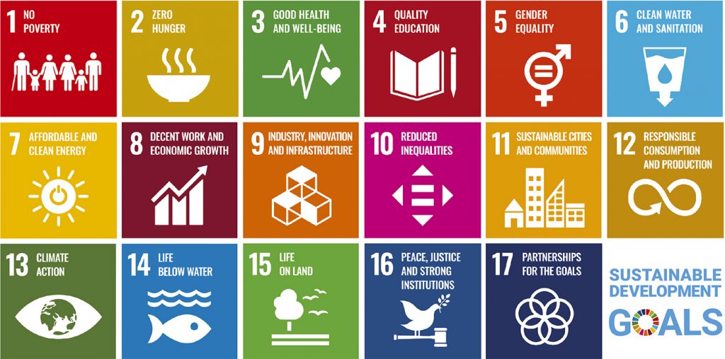
Sustainable Development Goals
In 2015, the United Nations formulated seventeen Sustainable Development Goals (Fig. 1). These goals serve as a blueprint to facilitate a peaceful and prosperous future for people and the planet.
Sustainable MIM
Because these objectives are interlinked on many levels, they can easily be connected to manufacturing technologies such as MIM. Two goals, 9 and 12, which deal with building resilient infrastructure, promoting inclusive and sustainable industrialisation, fostering innovation and ensuring sustainable consumption and production patterns, are clearly linked to MIM (Fig. 2).
In recent years, these goals have been considered more closely by the European MIM community. In a 2021 European Powder Metallurgy Association (EPMA) workshop, attended by a large number of representatives from the European MIM industry, participants exchanged views on important factors for MIM with regard to digitalisation, quality and sustainability. The results of the discussion were put into a roadmap that reflects the vision of the European MIM community for the coming years (Fig. 3).
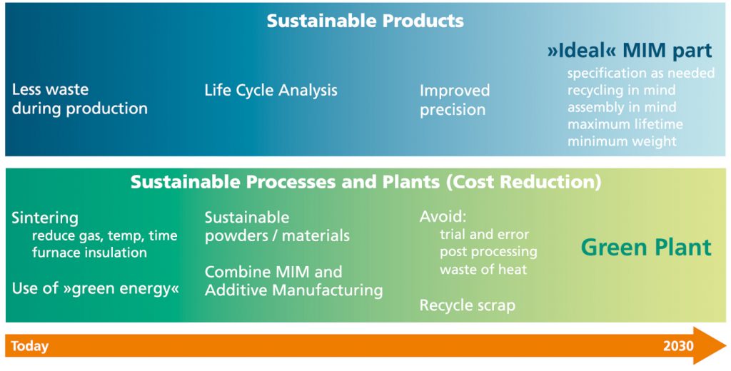
As the figure shows, actions at the time focused mainly on waste, material and energy reduction, as well as the use of green energy. The use of LCA to properly assess the sustainability of products seems to be an important next step for future years.

Future improvements in MIM
Of course, in order to improve on a situation, it must first be properly understood. As process capability improves, use cases for MIM will increase; in the long run, many factors may come together to create an ‘ideal’ MIM part. Although such an ideal part and the factors that influence it may be defined in different ways, they can be based on previously mentioned topics, such as LCA, and a deeper understanding of the processes, interactions and requirements of a specified application (e.g., an improved design for an extended period of use, second-life use or recyclability).
With regard to processes and manufacturing plants, the use of more sustainable materials and the combination of MIM with Additive Manufacturing are necessary next steps towards green production. This includes using more reliable data collection and generating a deeper process understanding, avoiding trial and error cycles in application development, reducing the necessity of post-processing and the resulting energy wastage, and recycling scrap more efficiently. A very clear common understanding within the group who developed this roadmap was that everything must take the economic perspective into account, ultimately leading to cost reduction.
Given the cost of production, there is a well-known visualisation of the influence that certain stages of manufacturing have in relation to the costs (Fig. 4). Tied to this is the concept of lean innovation, which is based on applying lean principles to create value by smart design and continuous improvement.
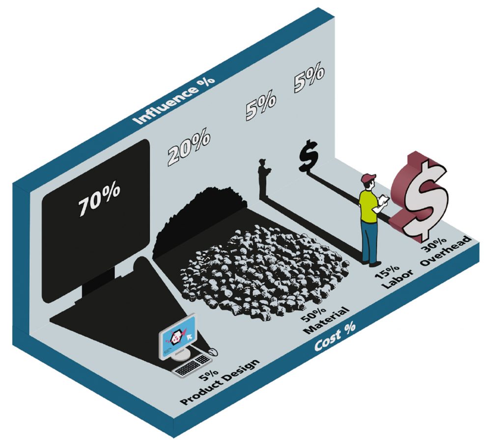
This way of thinking already intrinsically and specifically includes a view on sustainability, but, with a clear focus on the specific production environment and associated cost savings (e.g., by minimising waste) it connects the goals of an ideal MIM part and green manufacturing plants and shows the importance of implementing more viewpoints into a product’s design. This also applies to sustainability considerations and must be based on tools that can be used to achieve this.
Life cycle assessment
Because LCA is a central tool for approaching sustainability, some core elements and aspects are covered here, as well as the two main ways to make use of it.

Four steps of LCA
LCA is defined as a methodology to assess the environmental impact of a product, process or service throughout its life cycle: from raw material acquisition, through production and its use and disposal (or end-of-life use in the case of products). It is a standardised procedure as per ISO standards, mainly ISO 14040 and ISO 14044. The LCA procedure can be divided into four steps:
- Goal and scope: definition of a product system, functional unit, reference flow, system boundaries, assumptions, limitations, data quality requirements, allocation procedure, impact assessment and documentation
- Life cycle inventory (LCI): resources, energy, emissions
- Impact assessment (LCIA): environmental and human impacts
- Evaluation/interpretation: definition of priorities, sensitivity analysis, optimisation potentials, balance comparison
Defining the goal and scope of the LCA is the first step. This is a complex process but provides a framework for the entire analysis and a means to interpret the results, assess the LCA itself and make sensible comparisons with other LCAs. By definition, an LCA encompasses the entire life cycle of the product system; however, there are further variants that use the LCA approach but limit the analysis to certain parts of the product system’s life cycle. Such variants are depicted in Fig. 5.
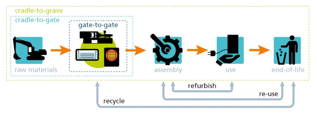
LCA can be referred to as a cradle-to-grave analysis, but partial LCAs can be done from cradle-to-gate, eliminating the application phase in the case of physical products and their end-of-life scenarios (e.g., second-life use, recycling), or from gate-to-gate (e.g., which can focus on a distinct manufacturing part within a product’s life cycle).
LCA in the MIM industry
The MIM industry is primarily focused on providing metal parts. Therefore, assessments that end at the gate are more easily obtained because data about the application stage of parts may be hard to get, depending on the specific product.
The primary use of LCA is as an assessment tool, providing an evaluation of technologies, products, processes and more. In that respect, it can help in making decisions within developments and be used in consulting, to characterise production systems and analyse optimisation potential. It can also help to select environmental performance indicators and can facilitate communication (e.g., for acquisition), supported by an Environmental Product Declaration, or for marketing, by providing benchmarks.
Essentially, LCA is always used for comparison purposes, such as a comparison of situations at different times (progress), of process A versus process B for a specific product (e.g., MIM vs. investment casting), process variant A versus process variant B (e.g., sintering MIM parts in continuous vs. batch furnaces), design A versus design B, the greenhouse gas (GHG) emissions of process steps (e.g., powder production vs. injection moulding vs. sintering), supplier A versus supplier B or something else.
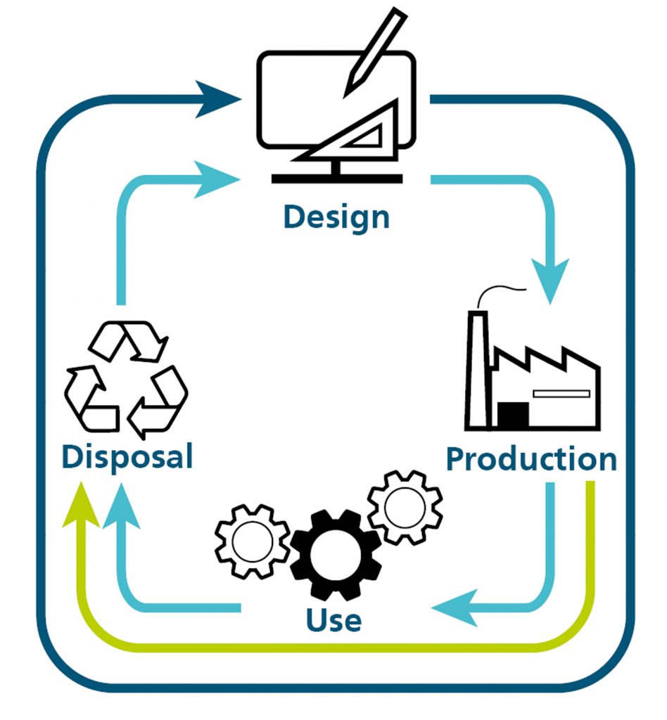
The second way to use LCA is not only as an assessment tool but as an integral part of the product design (Fig. 6). Because LCA can implement many factors, elements may be included that provide additional value, such as socio-economic factors, political factors such as raw material dependency, or materials and manufacturing alternatives. When such factors are required for decision making within the design phase of a product, LCA-based scenarios can be integrated into that modelling. Approaches to do this in an automated fashion and thus offering means to optimise a product design based on, or at least including, sustainability aspects, are being increasingly developed.
GHG Protocol
In the late 1990s, an initiative was started to place more emphasis on GHGs with the GHG Protocol. This led to the development of the GHG Protocol Product Life Cycle Accounting and Reporting Standard, which can be regarded as a special form of LCA. It provides “a general framework for companies to make informed choices to reduce greenhouse gas emissions from the products (goods or services) they design, manufacture, sell, purchase or use.”
This clear focus on GHGs has probably influenced the way sustainability is discussed nowadays, particularly in terms of CO2 emissions as a CF. Emission levels are already determined by many companies, on the one hand to analyse the CF of the company itself in a gate-to-gate manner, and on the other hand to provide a product carbon footprint (PCF).
Within the GHG protocol, the scoping (which is the first part of an LCA) is defined in three emission levels, to provide more standardised guidance for companies. Scope 1 emissions are direct emissions generated by the company’s owned or controlled sources. Scope 2 and 3 emissions are indirect emissions, with Scope 2 emissions including indirect GHG emissions from purchased or acquired energy, such as electricity, steam, heating or cooling, generated off-site and consumed by the company. Scope 3 emissions are those that occur in the value chain of a company, as “the result of activities from assets not owned or controlled by the reporting organisation but that the organisation indirectly impacts in its value chain” – as expressed by the US Environmental Protection Agency. These can be defined as either upstream emissions, related to purchased or acquired goods and services (i.e., cradle-to-gate), or downstream emissions, related to sold goods and services and emitted after they leave the company’s ownership or control (i.e., gate-to-grave).
Scope 3 emissions are manifold and stem from various process elements, and so are often not reliably quantifiable. Therefore, companies are often not expected or required to calculate life cycle inventories for individual products when calculating Scope 3 emissions.
In the following, we look deeper into the technological steps of the MIM process and provide an estimation of the relative impact of process elements on the CF of MIM products.
The MIM process
From a technological view, the core process of MIM is usually depicted as starting with powder and binder, followed by feedstock preparation, injection moulding, first-stage debinding and finally thermal debinding and sintering. When applying the cradle-to-gate view, the acquisition of raw materials, as well as powder and binder production, and secondary operations have to be included. In the following, we will go into a little more detail in these steps regarding selected sustainability aspects and provide the aforementioned estimation, based on the authors’ experience.
Raw material acquisition
The raw materials for a MIM product typically comprise multiple different materials from different sources. Metal powders can, of course, be derived from ores that must be processed to gain a pure metal or alloy. The location of natural resources – and, with this, the potential dependencies on certain countries, as well as the conditions of extraction – are topics that should be increasingly considered in the future. These factors already drive politically-motivated approaches to reduce dependencies on problematic sources.
An additional approach is to focus increasingly on recycling to slow down the depletion of natural resources. Also, the more that recycled materials can cover the demand, the fewer the dependencies on potentially problematic resources. However, setting up recycling systems is a complex task, often from a technical perspective alone, but definitely also from a logistical point of view.
Knowledge about the amounts and locations of certain materials in complex systems such as cars, cell phones, etc., as well as how to recover components, is crucial and involves the generation and handling of complex data sets. This may be facilitated by smart designs and approaches to improve the traceability of components (e.g., by tagging), but is certainly a topic for development.
Thus, regarding sustainability, replacing problematic sources, improving raw material acquisition conditions, increasing the amount of recycled raw materials and, of course, technologically improving the processes can lead to improvements and, for example, lower the CF.
Powder production
There are different processes to produce metal powders, such as oxide reduction, electrolytic deposition or atomisation. Most powders used in MIM are produced by gas or water atomisation. Another powder often employed is carbonyl iron powder, which is produced by the thermal decomposition of carbonyl iron. Water and gas atomisation use molten metal to feed into the media stream of water or gas (typically nitrogen or argon) in which the high shear atomises the melt into droplets that solidify and form the powder particles. The particles are more irregular in water atomisation and usually highly spherical in gas atomisation. Also, water atomised powder usually contains more oxygen, which may have to be reduced later in the process.
Fundamentally, the production of metal powders is an energy-intensive process and thus offers the potential to reduce the CF of powders by using green energy as much as is economically possible. Furthermore, the use of scrap as a raw material source can significantly reduce the CF. The use of large amounts of process media that require a lot of energy in their respective production (e.g., argon) or that must be purified, as in the case of water, add to the CFs of the processes.
Binder component production
Binder components comprise a smaller share of the feedstock, roughly 40% by volume, but are considerably less by weight, due to the greater density of metals. Their specific components differ for different binder systems, but they are always organic compounds. They must be as residue-free as possible during the MIM process chain. Sustainability is a major topic within the chemical industry and has resulted in many ventures to make chemical production more environmentally friendly.
One trend is recycling waste material to break it down into simple chemicals that can act as a base material for a variety of products. An example is the production of polyolefins (e.g., polyethylene, polypropylene), in which cooking oil or residue from vegetable oil production is recycled as a source material. The customer can decide how much of the source material should be used to reduce their CO2 reductions. Because such approaches have to be built up, they are initially more costly, but they can contribute to minimising the use of oil from fossil sources.
Feedstock production
The production of feedstock is done by using different types of mixing technologies, such as kneading, high-shear mixing and compounding/extrusion. The reuse of feedstock (e.g., from sprues and runners or defective green parts) may require some additional regranulation to achieve reusable feedstock granulate. Feedstock production may be run continuously, which makes sense for suppliers of large feedstock quantities, but is often done batch-wise, especially when feedstock production is done by part manufacturers in-house.
Because feedstock for MIM is always thermoplastic, the mixing must be done at elevated temperatures to melt the binder completely (i.e., between 120°C and 200°C). Aside from this thermal energy aspect, shear must be applied to homogenise the feedstock as well as possible, for which rotating elements such as blades or screws are used against the material’s resistance. This torque, applied via electrical motors, as well as the energy for heating equipment and materials, add to the energy consumption of the MIM process.
Injection moulding
During the injection moulding step, the feedstock is heated and injected into a heated mould to solidify and generate the green part. The two primary types of high pressure injection moulding machines are the more traditional hydraulic machines as well as more modern electrically-driven machines. According to various sources, electrically-driven machines consume less energy, require less maintenance and produce less waste than alternatives such as those using hydraulic oil, which has to be replaced regularly. To increase productivity and reduce the energy required for part production, tools with several cavities can be used. Feedstock can be recycled in-process, as mentioned above, and is usually added to some extent to fresh feedstock in production.
First-stage debinding
In first-stage debinding, the major share of the binder system is removed to form pores through which gaseous decomposition products may leave the parts in the following thermal debinding, without damaging the parts. This removal of binder in first-stage debinding is nowadays mostly done either chemically or catalytically. In chemical debinding, soluble components of the binder system are removed by immersing the green parts in a suitable solvent, usually at elevated temperatures, limited by the boiling point of the solvent.
Suitable solvents depend on the binder system and can be water, acetone, hexane, trichloroethylene, or others. Although some systems can reuse the solvents after distillation, solvents always evaporate during the debinding. Therefore, aside from the energy consumption of the technical equipment, the handling of solvents is a factor with regard to sustainability. The solubilised and post-distillation collected ‘waste’ of binder components is often disposed of. As the chemical industry is increasingly making use of waste material, improved recycling of these materials may improve the sustainability of the whole process in general.
Catalytic debinding is used for binders based on polyoxymethylene (POM), which are widely used in the MIM industry. POM is chemically decomposed by reacting with nitric acid at elevated temperatures. The resulting toxic formaldehyde is burned off to prevent any harm to people, which results in direct emissions.
First-stage debinding clearly contributes to the emissions, potentially with direct emissions additional to CO2 equivalents from energy consumption.
Second-stage debinding and sintering
Second-stage (thermal) debinding is often carried out in the same furnace that subsequently sinters the MIM parts. Although this can be done separately, which may lead to parts with lower amounts of residuals, it requires the handling of mechanically highly unstable ‘brown’ (completely debound) parts. The two main options regarding furnace technologies are batch furnaces and continuous furnaces.
Both technologies have technical advantages and disadvantages favouring one or the other. But, from a sustainability perspective, if both technologies were used, continuous furnaces could achieve less energy per part, if the load with parts were sufficiently high, but many more factors must be taken into consideration to determine the ‘best’ option.
Because some organic material is typically burned off in the early phase of a furnace cycle, and sometimes hydrogen is used partially or entirely as a sintering atmosphere, the sintering atmosphere is flared after leaving the furnace.
Thus, prolonged high temperatures certainly result in the sintering step being one of the more energy-intensive steps in the MIM process chain.
Secondary processing
For many MIM parts, secondary processing is an integral part of the process chain. The variety of potential secondary operations is very wide, from simple mechanical calibration to adjust the dimensions of distorted parts, to multiple ways to treat the surfaces of parts, machining critical features such as threads, basic heat treatment and Hot Isostatic Pressing (HIP). These secondary processes may lead to further emissions such as removed excess material and certain chemicals, additional to their respective energy consumption, and can contribute considerably to the CF of a part.
Further process-related aspects
Aside from the direct process technologies, there are usually several process-related topics that must also be considered within an LCA, including process-accompanying analytics, data processing, internal logistics and more.
Qualitative impact assessment of the process step
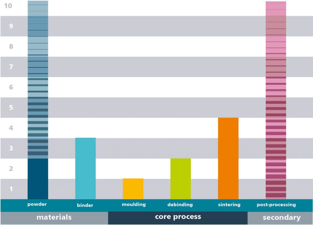
Having looked a little closer into the MIM process steps and some of their respective sustainability aspects, we want to give a qualitative assessment of the contribution of certain process elements to the CF of MIM parts. Given the complexity of LCA and the variability of the process chains of specific MIM parts, Fig. 7 provides an estimation.
As can be seen, the largest contribution is attributed to the powder and potentially to secondary operations. Still, both contain aspects that should be discussed further. For the powder, several sources state the huge impact between virgin powders and those from recycled materials. Depending on the specific metal or alloy, factors of 2 to 20 can be found concerning the CF between those sources. Of course, the Scope 2 indirect emissions of virgin powders have different aspects, potentially related to mining, raw material processing and more, that impact the CF severely.
Secondary operations can also impact the CF significantly, depending on their specific use for a certain product. Heat treatment and HIP may be closer to a sintering process in terms of CF, whereas other operations contribute very little. The binder also contributes considerably, because the synthesis of polymers and other chemicals consumes significant amounts of energy. However, because the CF is usually given based on the weight, the low density of organic materials compared to powders puts them into perspective.
The core MIM production that uses powders and binders (and often feedstocks) within Scope 2 would mainly focus on the elements of injection moulding, debinding and sintering. Some minor post-processing is potentially also included, but processes such as heat treatment and HIP are often outsourced. Within these core steps, sintering contributes most to the CF; injection moulding contributes the least.
In principle, the process elements with the largest contribution to the CF are also the ones with the largest potential to reduce it. Still, the relative energy savings potential within each step depends on how well the processes and the technology are optimised, and on potential alternatives, such as in the case of virgin vs. recycled powders. Process steps that are rooted in large industries, such as injection moulding, also benefit from developments elsewhere and may be further along with regards to their specific optimisation potential.
When analysing the PCF of a specific MIM part, the actual contribution of the process elements will, of course, be different. But, if more and more companies provide that information, for example, via the Scope 3 approach, the PCF of a final part can be quickly calculated by using the information within the entire MIM customer–supplier chain. This will also provide a more detailed image of the MIM technology and make it more easily comparable to others.
The initial overview of the European MIM community’s vision shows the motivation to take important steps in reducing energy consumption in the coming years. This is already supported strongly by Germany’s MIM Expertenkreis (MIM Expert Group) and the EPMA, with plans to take further steps with partners from around the globe such as the Japan Powder Metallurgy Association (JPMA) and North America’s Metal Injection Molding Association (MIMA). These actions will contribute to a more sustainable MIM industry as well as greener production plants.
Authors
Dr Sebastian Boris Hein
Head of Department Powder Technology
Fraunhofer Institute for Manufacturing Technology and Advanced Materials IFAM
Wiener Straße 12
28359 Bremen
Germany
www.ifam.fraunhofer.de
[email protected]
Dr Frank Petzodt
Ingenieurbüro Dr. Petzoldt
Eschacker 5
27607 Geestland
Germany
www.petzoldt-consulting.de
[email protected]


