


Don’t panic! A hitchhiker’s guide to metal Fused Filament Fabrication (FFF)
This is a story from what once looked like the edge of the metal Additive Manufacturing universe. A decade ago, the idea of a Metal Injection Molding feedstock-like filament for Fused Filament Fabrication (FFF) was the stuff of beer talk, but then things started to happen. Through a Facebook group called ‘FFF Metal 3D printing’ I discovered what felt like an underground community, driven by the seemingly impossible prospect of ‘printing metal’ on a shoestring budget. Amongst the dramatic images of failed builds and small piles of melted steel, posts by Sascha Lenze stood out. Here, he shares the story of L.B. Bohle Maschinen und Verfahren GmbH’s journey towards the Material Extrusion (MEX) of metal-containing filaments for industrial applications. Welcome to the new frontier! First published in PIM International Vol. 17 No. 2, Summer 2023 | 15 minute read | View on Issuu | Download PDF
More than four years ago, when I first became aware of metal Fused Filament Fabrication (FFF), it was Markforged and its Metal X system that brought it to my attention. Because our company’s focus was – and, for many reasons, still is – on 316L (1.4404) stainless steel, we already had some experience of metal Additive Manufacturing service providers, mostly using Laser Beam Powder Bed Fusion (PBF-LB). The low entry price of all-in-one solutions like that of Markforged, when compared to other metal AM processes, was immediately attractive to us.
We contacted Markforged to get more information about its product and, after some email conversations and phone calls regarding the prices for the particular part we intended to manufacture in the future, we met to explore the possibilities. To cut to the chase, at the end of that day we realised that such near-automated ‘all-in-one’ desktop metal Material Extrusion (MEX) packages were not the right choice for us. Because of our company’s background in mechanical handling and material processing solutions, we place high demands on part specifications and performance. In our opinion, such systems struggle to deliver for the given material.

Subsequently, after almost no information regarding metal FFF could be found online except what you can read about Metal Injection Moulding, and feeling a bit like Arthur Dent after his first teleport to the Vogon ship from Earth (rest in peace, Douglas Adams), we were lucky enough to discover a review on YouTube by Andreas Weiss of AMPro3D [1] showing the opportunities of sinter-based metal and ceramic FFF using filaments manufactured by Powder Technology and Additives (PT-A), a small company from Dresden, in the eastern part of Germany.
Still starry-eyed enough when it came to the complexity of the whole metal FFF procedure, I gave them a call, and after an hour (or so) of talking to Dr Karsten Pischang about his materials and the potential of the procedure, we were happy to order a 1 kg spool of 1.75 mm diameter 316L filament for some initial testing. With hindsight, one could mention that filaments of 2.85 mm diameter would probably have been a better choice because the highly-filled materials tend to break easily. However, our intention was to use the existing FFF machine we usually print polymers on (and, as an aside, this hypothesis did not play out anyway.) There were, of course, obstacles, but more on that later.

First results from metal filament in an ‘everyday’ printer
One of the first advantages that probably catches everyone’s eye when it comes to metal FFF is the opportunity to use an existing everyday polymer printer, which I suspect is at hand in pretty much every modern engineering or design business these days. In our case, it was a Sparkcube, a generic CoreXY DIY kit by Sparklabs, which had already been around in the workshop for a few years (Fig. 2). It is made from printed plastic parts, 2020 aluminium extrusions and (mostly) open-source hardware and electronics. All of the components – if not bought as a kit – could be easily self-sourced at the ‘usual suspects.’
With many years of experience building such machines from scratch, my colleague Manfred Groth and I chose it to give us the most freedom when it came to modifications for the specific demands of a process or application. The machine was equipped with a single printhead, a brass nozzle fitted ‘V6 All-Metal HotEnd’ manufactured by E3D in the UK, and a proprietary extruder by Sparklabs.
After having a hard time removing concrete-like filament residues from the hotend repeatedly, we replaced the extruder with a genuine Bondtech Dual-Drive BMG type (which was lying around at home anyway) and this reduced the risk of the extruder gears digging into the filament. Although there was no noticeable wear on the brass nozzle after many hours of builds, we switched to a hardened steel nozzle later on, primarily because brass nozzles are known to contain lead, and we were in fear of contamination issues on our stainless steel prints. That said, nickel-plated nozzles could probably be an option, depending on the desired material.

After the first few printing steps, another obstacle arose when we realised the filament was so brittle that it was broken easily by the printhead changing orientation with a reverse acceleration that was too high. Because the material always broke directly on top of the extruder, it was obvious that the guidance of the material to the extruder needed to be improved using a PTFE tube and, in the same step, move the filament spool on top of the printer over the centre of the print bed. There are some solutions on the market that add a second gantry for moving the spool synchronously to the printhead to overcome this issue, but fixing the tube directly to the spool holder gives pretty much the same result at almost no cost.
Learnings on adhesion and part removal
Bed adhesion has never been an issue when staying within the parameters recommended by the filament manufacturer, and neither was warping, unlike the other manufacturers’ materials. A well-levelled and slightly warmed (30°C) borosilicate glass bed printing at 40 mm/s printing speed with a hotend temperature of approx. 130°C worked pretty well, but the prints often broke during removal due to the lack of flexibility of the glass. The fact they are approximately the strength of chocolate does not help much either.
For small parts, a razor blade works quite well to remove the part from the bed, but bigger and especially flat parts have always been a problem. We tried a broad variety of print plate materials and there were some that worked well for most geometries – PP foil, to name one – but the real game changer became apparent as we were playing around with some BASF Ultrafuse 316L filament, which we received together with BASF’s support layer material as a sample for testing. BASF strongly recommends using Magigoo applied on the glass bed for an overall better bed adhesion and prevent the parts from lifting due to warping of the material. As a benefit, Magigoo is water-soluble, and when stored under water for a while the print self-separates from the glass. When printing a so-called ‘raft’ underneath the part, the process can be accelerated even further because the surface that comes in direct contact with the glass is way smaller with spaces at regular intervals.
The benchy test

A benchy is probably not what is typically produced as a trial object using an industrial Additive Manufacturing workflow, with material and machines typically being in a well-configured state, and there is probably no reason to print one except for the kids at home to have something to play with (Fig. 3). But those who are familiar with FFF would certainly agree that a material having what one may call ‘unknown characteristics’ can be a good starting point to get an overall impression of its behaviour in virtually any feasible geometry printed without supports.
Still, printing at low speeds with a given 400 µm nozzle diameter and a 150 µm layer height, the surface quality looked great, probably benefitting from the same optical effect as carbon or glass fibre-infused filaments, and the overhangs came out nicely. The only real drawback was that bridging [2] did not work well compared to what one would expect from polymers, which can probably be explained by the high specific weight of the metal-loaded material in combination with the low melting temperature of the binder system.
After switching from fan cooling to pressure air cooling by applying air by tube directly to the build area, things got better, but the results are nowhere near to anything we are used to from polymers. Supports can be helpful, but, as you can imagine, they can be difficult to remove depending on the geometry, and even harder when done post-sintering because you are dealing with stainless steel. Solutions such as interface layer material, such as O3 filament from BASF, can be useful as it enables the user to remove the metal supports easily by simply breaking the interface layer. A significantly better surface quality on steep overhangs is a good additional advantage. A printer equipped with two printheads is, of course, needed.
The challenge(s) of sintering
Manufacturing bottlenecks are something that we all have to come to terms with at some point. With some finished builds in our hands and an awareness of the maturity of the MIM process giving us some confidence that all would be okay, we did not expect to have quite so many difficulties finding a sintering services provider. Well, we learned the hard way and, to put it mildly, the delay was more like a cork in a bottle.
Along with having a hard time finding someone who would agree to sinter, the sintering furnaces often used for ‘toll-sintering’ are sized mostly for small batches of up to a thousand or more small MIM parts and, therefore, are way too big to process a batch of only a handful of parts for an acceptable cost. On the other hand, the option of putting our parts ‘somewhere in between’ within a larger sintering run is no solution either, because the sintering provider would go crazy on the diversity of different geometries of the parts you send them to sinter, which would take up too much space in the furnace.
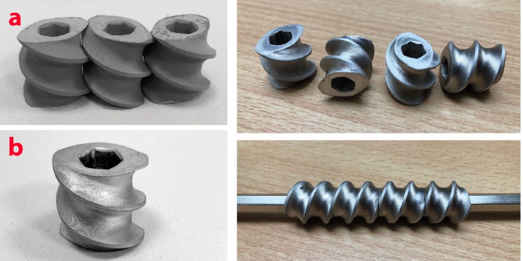
After searching for a while and feeling somewhat disillusioned, we came back to PT-A and were relieved that they agreed to help us out. We sent them our small collection of green parts (Fig. 4 shows a few). They did the debinding and sent the brown debound parts to Fraunhofer IFAM in Dresden to do the sintering, including some trial parts printed to one-shell wall thickness only (400 µm) and as low as 10% infill, which was way off the recommended specifications one usually comes across when it comes to metal FFF.
Putting the results to the test
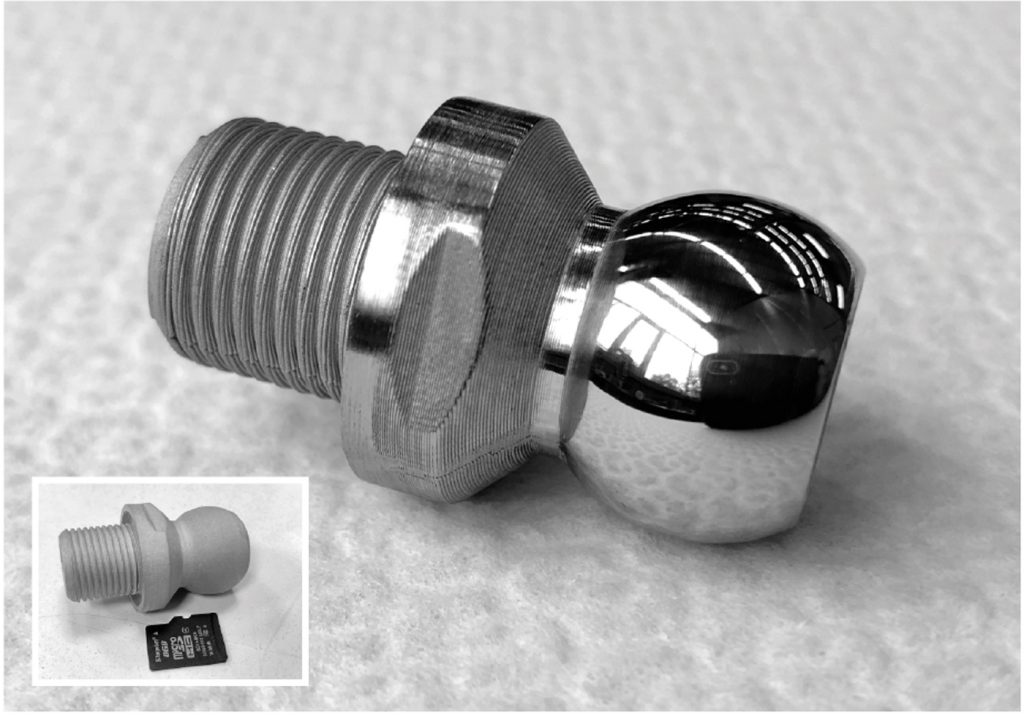
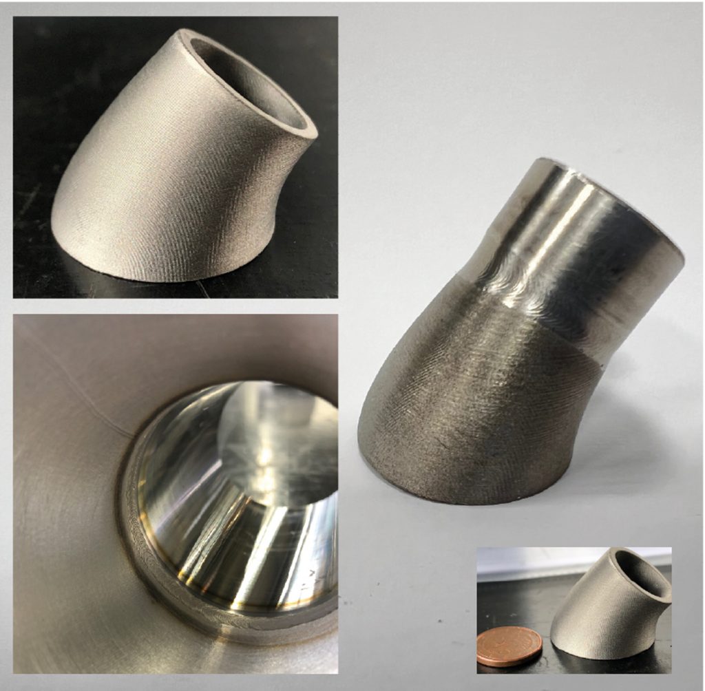
A little while later, we received the results in our mailbox and were surprised regarding the convincing quality of the parts. The surface was smooth and shiny and our first checks with the X-ray spectrometer, borrowed from our quality department, told us the material met the expected properties. Because most of the future builds we were planning were, at that point in time, products that would require some level of post-processing, we used the time to make some plans about how to proceed, including grinding, lathing, drilling and welding as well as polishing the sintered parts.
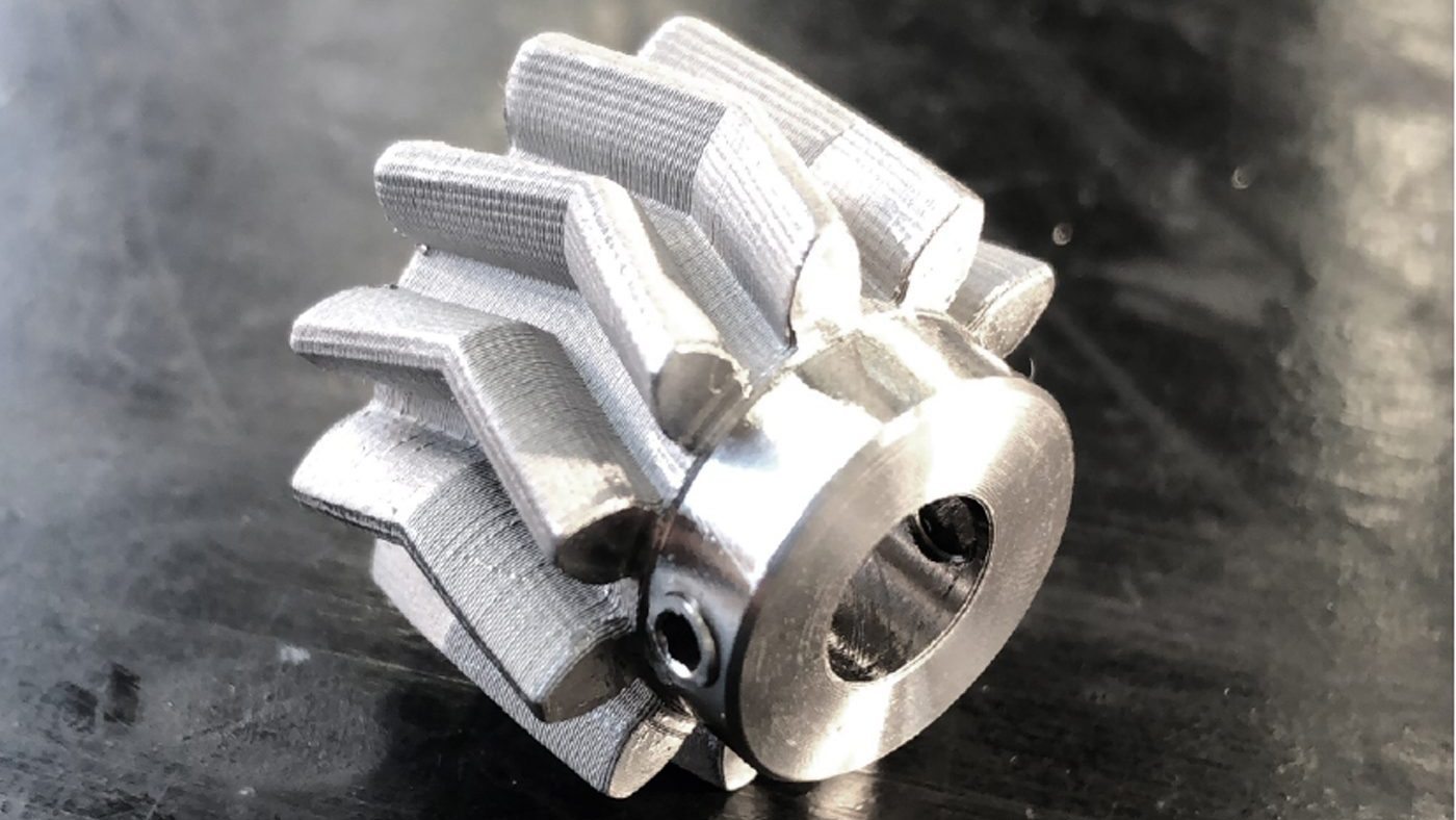
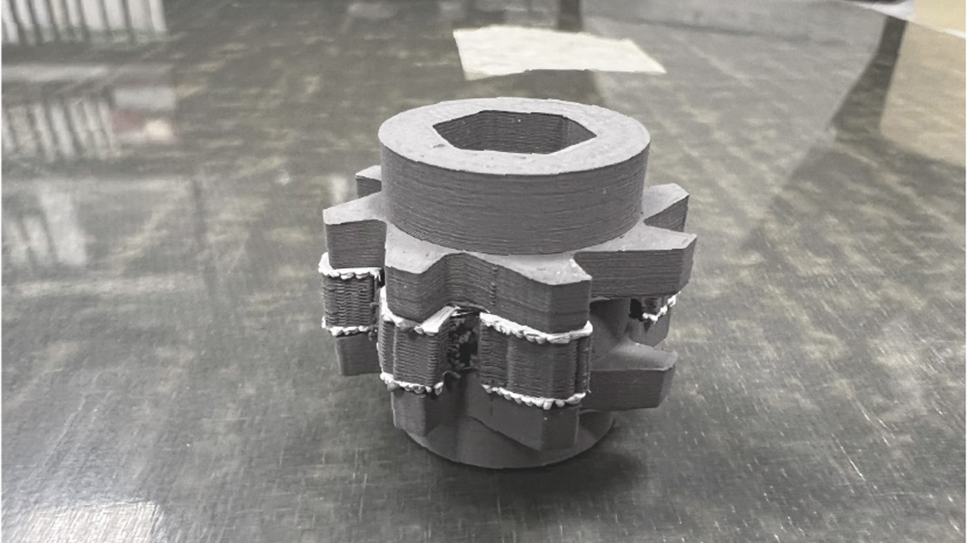
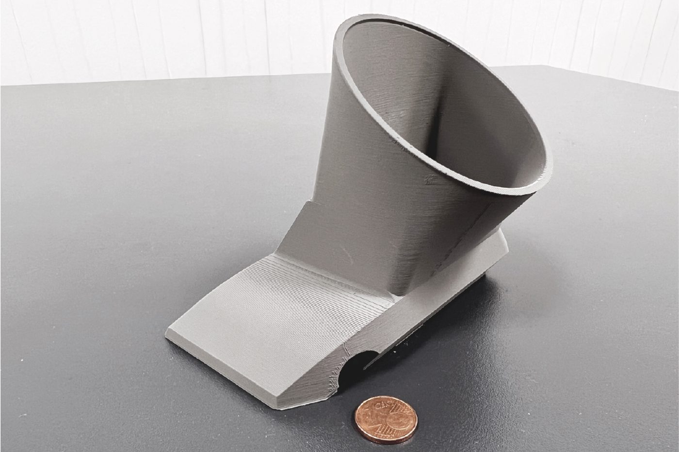
Grinding and lathing performed extremely well on the sintered parts. The longboard herringbone drive gear shown in Fig. 5, used in an electrical drive system, was designed by Manfred as a drop-in replacement for a polyamide part that broke from time to time due to the motor’s torque being too high when accelerating. For TIG-welding a printed part for conventional production (Fig. 6), we had some exciting first results followed by some setbacks on the next batch of sintered parts, which later on we could attribute to sintering atmosphere issues. Polishing of the parts worked fine as well (see Fig. 1); however, grinding too deeply into the material’s surface caused a ‘breakthrough’ of the first shell. This resulted in an area rich in small defects being exposed, which is an issue that is probably print density-related and needs to be addressed in the future.
Should we stay or should we go?
With long delays due to our persistent sintering availability issues, combined with useless or defective parts returning from sintering and no real clue about the root cause of the issues, we started to ask ourselves whether we should better stop at this point and forget about sinter-based metal FFF or continue on the journey. For Manfred and me, there was little doubt about the answer – we consider the procedure well worth the effort that we had put in over the years. Fortunately, our management’s thinking was in harmony with ours, so we started making plans for a dedicated in-house facility, including a printer, debinding unit and a sintering furnace.
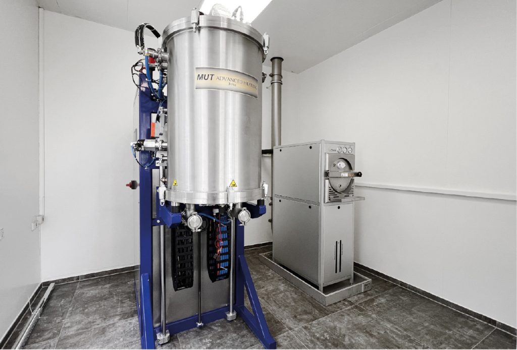
With positive experiences regarding the materials as well as the support offered, we decided to continue using materials produced by PT-A. Because the binder system is dissolved by acetone, we chose a Loemi semi-automatic debinding system with integrated solvent recovery (Fig 7, right). We did not have much experience when it came to sintering furnaces, so we had to rely on the several positive reports that we received when discussing the procedure. We wanted to be able to sinter a wide range of materials, so maximum flexibility was our focus. In making our final decision, we chose a MUT furnace capable of operating under H, N and Ar (Fig. 7, left).
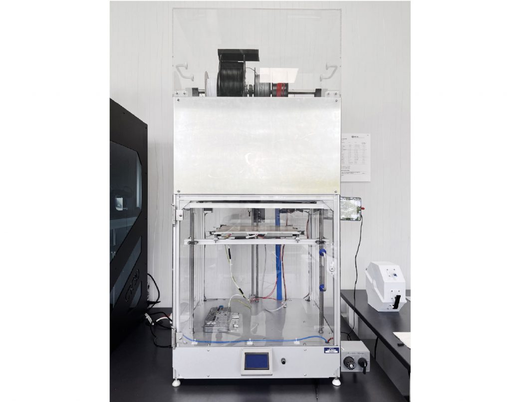
For a dedicated FFF machine, we had been in frequent contact with Christian Reil of CR3D, a small producer based in Bavaria. The I433 we finally ordered is an industrial-grade dual interchangeable extruder IDEX printing system based on, amongst others, Duet3D open-source hardware and leaves nothing to be desired when it comes to freedom of modification (Fig. 8).
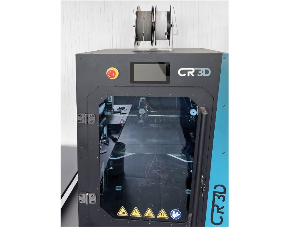
The printer arrived at the end of 2022 and since then we have had the opportunity to print a nice collection of 316L parts, often using Al2O3 interface layers (Fig. 9). As test parts we have produced 1 cm³ cubes (when sintered), which we plan to distribute evenly in the furnace chamber to evaluate temperature uniformity.
As a result of producing a lot of defective green parts when testing of the printer, we decided to purchase a cheap filament extrusion system, including a shredder built by Felfil, Italy, to experiment with filament recycling in order to save some money on the expensive filament.
Loemi delivered the debinding system at the beginning of the year and the company was on site for commissioning a few weeks later. The machine is built like a tank and, in addition to its original intended purpose, we created a ‘non-invasive’ acetone smoothing conversion kit for ABS and ASA parts that we sometimes need to smoothen, which works pretty well with the benefit that all the acetone is returned in the process.
A few weeks ago, after postponements due to problems with the delivery of electrical components, our MUT sintering furnace arrived on site. Sadly, because of some missing hardware relating to the gas supply, the commissioning is delayed. So, unfortunately, I cannot report much about our sintering journey yet.
The journey from here
For having come such a long way, it still feels like we have just started and there is a colourful bouquet of challenges waiting for us to overcome in the future. Because we have – as you may already have recognised – a less-than-scientific approach to the procedure, we started a partnership with Steffen Florian at the FH Münster University of Applied Sciences to address green part density and other questions on the process. So, we will probably have some answers for those who have been asking for numbers at some point in the future.
The company that I work for, L.B. Bohle Maschinen und Verfahren GmbH, builds machines and develops solutions for customers in the pharmaceutical and metal AM industries all over the world. Our portfolio includes vacuum granulators, coaters, powder blenders and systems for continuous manufacturing. With parts of our machines coming into contact with active pharmaceutical ingredients or metal powders, we have a strong focus on the properties of AM parts in order to avoid contamination of the products. Material-specific properties need to be met, for example, when it comes to corrosion resistance, density and the surface quality of builds.
With a qualified FFF-based metal AM operation as our final goal, there is still much to do and there are many issues that need to be addressed on our way. So, let’s see how far we can get. If there are questions, please let me know. I am always open to a constructive debate regarding the procedure.
With the whole process looking insanely complicated to operate, my only advice? Don’t panic!
Author
Sascha Lenze is a certified electrical technician, software developer PLC/HMI and metal FFF enthusiast with more than ten years’ background in FFF/FDM polymer AM as a hobbyist as well as a professional.
[email protected]
www.lbbohle.de
References
[1] www.youtube.com/watch?v=5PNXb5dptr8
[2] Bridging is a FFF/FDM related term for the nozzle extruding a line of material between two parts of a geometry without supports, suspending the material in mid-air.


