


World PM2022: Research into the Binder Jetting of aluminium, Ni-free stainless steel, hardmetals and metallic glass
As exploration of the potential of metal Binder Jetting (BJT) picks up pace, so does the diversity of materials processed using the technology. At the 2022 World PM Congress, organised by the European Powder Metallurgy Association (EPMA) and held in Lyon, October 9-13, a number of presentations reported on developments that looked at a range of materials with commercial potential for BJT, including aluminium alloys, nickel-free stainless steel, hardmetals (cemented carbides) and metallic glass. Dr David Whittaker reports for PIM International. [First published in PIM International Vol. 17 No. 1, Spring 2023 | 35 minute read | View on Issuu | Download PDF]
The Binder Jetting of aluminium alloys
A paper prepared by Matteo Zanon and Armin Mueller (Kymera International/Ecka Granules Germany) and Joseph Croteau, Joseph Workman and Tom Pelletiers (Kymera International/SCM Metal Products, USA) addressed the Binder Jetting (BJT) processing of aluminium-based alloys [1].
Due to the notorious stability of its alumina oxide layer, aluminium and aluminium-based alloys have been considered to be “inherently difficult” to process via BJT, due to the “general difficulties of sintering”. This perception has led to the fact that, while AlSi10Mg0.4 is one of the most common materials for Laser Beam Powder Bed Fusion (PBF-LB), until very recently no commercially available Al-based system existed for sinter-based Additive Manufacturing. On the other hand, aluminium components have been manufactured for many decades on a fully industrial scale by press-and-sinter Powder Metallurgy.

Kymera International has been at the forefront of these press-and-sinter developments with its well-known Ecka Alumix alloy series. By taking advantage of this experience in the sintering of aluminium alloys, new grades, specifically tailored to BJT’s requirements, have been designed, built and successfully consolidated to near-full density.
The work, reported in this paper, focused on the development of BJT grades of the well-known aluminium alloy AA6061. As-printed, sintered, and heat-treated properties have been characterised, showing the viability of the BJT process to produce lightweight aluminium-based components.
The prealloyed aluminium 6061 powder used was nitrogen gas atomised with the chemical composition given in Table 1. The powder had a nominal particle size of <63 μm and featured proprietary modifications to enhance its reactivity during sintering. The apparent density was 1.53 g/cm3 and Carney flow was 21.0 s/50 g.
![Table 1 The chemical composition of the pre-alloyed aluminium 6061 powder [1]](http://www.pim-international.com/wp-content/uploads/sites/2/2023/08/table-01-2-1024x115.jpg)
Each build consisted of thirty prismatic samples with X, Y and Z dimensions of 13.30, 6.15, and 40.75 mm respectively, with X being the recoater direction, Y being the print head direction and Z being the build direction. A specific aluminium-compatible binder was used. Each build was 500 layers thick and took 8 h and 50 min to complete. After printing, the build box was placed in a curing oven and held at 200°C for 12 h in nitrogen, followed by depowdering.
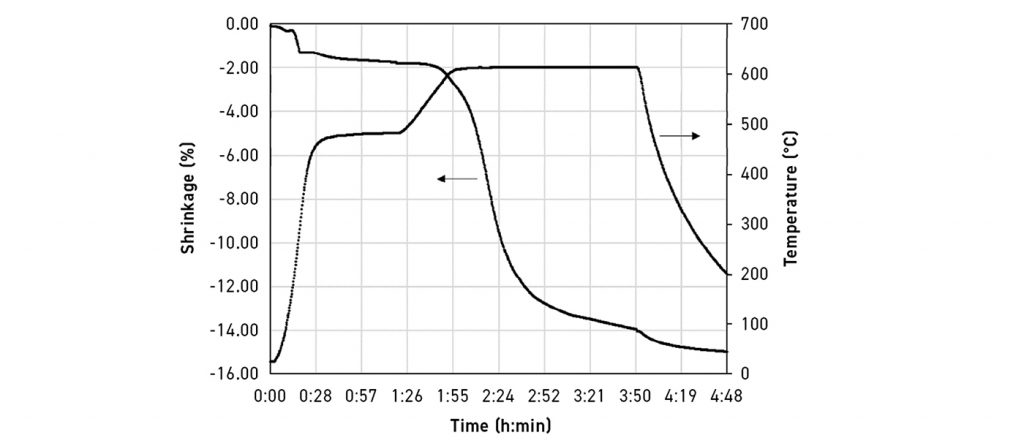
The prismatic samples were sintered in a vertical dilatometer to directly measure shrinkage during heating. The Z-axis of the sample was in line with the dilatometer pushrod and the direction of nitrogen gas flow. Samples were heated at 25°C/min to 500°C and held for 1 h to facilitate binder burnout, then ramped at 2°C/min to 625°C and held for 2 h to sinter.

There were six regions of interest observed during the sintering cycle produced by dilatometry, as shown in Fig. 2, where percentage shrinkage and temperature are plotted against time. During the initial ramp, ~1% shrinkage occurred between 200-300°C. This can be attributed to the particles rearranging. There was minor shrinkage between ~460-560°C, which was possibly due to a limited amount of liquid phase formation. Between ~560-605°C, the sintering rate increased, producing roughly 2% shrinkage. Above ~605°C, the sintering rate rapidly increased and 6% shrinkage occurred in under 30 min. This correlated to a super-solidus liquid phase in the Al-Mg-Si system facilitating rapid aluminium diffusion. After ~45 min above 605°C, the sintering rate began to slow and 14% shrinkage was observed at the end of the 4 h sinter cycle. When the furnace was turned off, thermal contraction was observed.
For furnace sintering, samples were placed in a graphite boat in the cold section of a tube furnace and purged with 10 scfh (~4.7 l/min) of flowing nitrogen. The graphite boat containing the samples was then pushed into the hot zone of the furnace, pre-heated to 500°C and held for 1 h. The furnace was then ramped at 2°C/min to 625°C, held for 2 h and then furnace-cooled.

The average density of furnace sintered parts, measured by Archimedes method, was 2.67 g/cm3 or 98.9% of theoretical density. A 2% weight loss was observed due to binder burnout. The average shrinkages in the X and Y directions were approximately equal, at about 16%, but 21% in the Z direction. The higher shrinkage in the Z direction was expected due to the inter-layer porosity commonly observed in metal Binder Jetting. Anisotropic shrinkage must be considered and accounted for when designing a part as it makes dimensional control more challenging. However, observing greater shrinkage in the Z direction emphasises the sintering reactivity of the material (i.e. the ability of the super-solidus sintering mechanism to eliminate porosity, in turn leading to more isotropic mechanical properties).
![Fig. 3 Four aluminium samples sintered in the same cycle. Nitrogen gas flow was from left to right [1]](http://www.pim-international.com/wp-content/uploads/sites/2/2023/08/fig-03-8-1024x569.jpg)
During sintering, parts tend to undergo some deformation and those closer to the gas inlet warp to a greater degree. This can be attributed to either the leading-edge oxidising more than the trailing material, or to cold gas impinging the part creating a thermal gradient. Fig. 3 shows four parts sintered together in one batch, where the nitrogen gas flow was from left to right. The quality of final parts was improved by better control over the oxygen content and elimination of thermal gradients by shielding the parts from direct gas flow. Fig. 4 shows a cross section of a sintered test bar; the extremely low amount of visible residual porosity confirms the Archimedes density assessment, i.e. the material was sintered to close to full density. The absence of contamination from binder residuals should also be noted, notwithstanding the short debinding schedule.
![Fig. 4 Cross-sectional microstructure of a sintered part, unetched [1]](https://www.pim-international.com/wp-content/uploads/sites/2/2025/01/fig-04-8-edited.jpg)
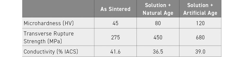
After sintering, samples were stored at room temperature and their hardness evolution was tracked periodically with Vickers microhardness checks. To understand the effects of solutionising on natural ageing, some samples incorporated a 530°C hold for 1 h after sintering at 625°C, followed by a water quench and room temperature natural age. To test the ‘T6’ condition (solutionise and artificial age), sintered samples were solutionised at 530°C for 1 h in a box furnace, water quenched and then placed in a pre-heated box furnace at 180°C for 16 h.
![Fig. 5 Vickers microhardness evolution over time of sintered samples stored at room temperature [1]](http://www.pim-international.com/wp-content/uploads/sites/2/2023/08/fig-05-8-1024x448.jpg)
6000 series aluminium alloys are known to ‘naturally age’ or precipitation-harden at room temperature. The as-sintered samples, which were furnace-cooled and stored at room temperature, had an average microhardness of ~45 HV and this did not change after 400 h (Fig. 5, left). In other words, they did not naturally age. This is probably due to Mg and Si, the alloying elements responsible for precipitation hardening, being already bound in coarse intermetallic phases, created either at high temperatures or in the super-solidus liquid formed during sintering and therefore unavailable to form precipitates. In contrast to this, samples which incorporated a 530°C solutionising step at the end of sintering, followed by a water quench, naturally aged to ~80 HV after 100 h and stabilised at that level. The transverse rupture strength was determined using the sintered, prismatic samples in a three-point bending fixture and a compressive load frame. Physical properties are reported in Table 2 for the as-sintered, solutionised and naturally aged, and the ’T6’ samples.
In conclusion, besides the intrinsic advantages of the BJT process, it should be noted that a fast debinding and sintering cycle was used in this study, with no lengthy, multi-stage heating ramps and holding times. Thus, the process is well suited to a continuous mass-production facility – a key requirement for the widespread adoption of BJT technology.
While high density can be very consistently achieved, once appropriate furnace conditions are in place, exact dimensional control remains the most challenging part of the sintering process, being controlled by the details of furnace set-up, atmosphere flow and thermal gradients. The Kymera International R&D team continues to improve the reliability of the process and to expand the availability of alloy systems.
Investigating the Binder Jetting of nickel-free stainless steels
Next, Lennart Hecker, Chistopher Schaak, Simon Hoeges and Patrick Koehnen (GKN Sinter Metals Engineering GmbH, Germany) discussed processing of nickel-free stainless steel through a combination of BJT and Hot Isostatic Pressing (HIP) [2].
Common industrialised stainless steels for BJT are 316L and 17-4 PH and these materials have recently been made available for many Binder Jetting systems. These two materials make it possible to cover an extensive range of applications in the chemical and pharmaceutical industries, mechanical engineering, and offshore applications. In addition, 316L is used for jewellery and both steels for medical instruments. A critical problem can arise in these applications: Due to the contact between the steel surface and the human body, an electrochemical release of nickel ions is possible. The released nickel ions can cause a nickel allergy. An EU study has indicated that the released nickel is negligible for different stainless steels (including 316L) when used as jewellery, but several manufacturers of relevant parts (implants and wearables) are still afraid that a nickel release could harm their end-users. To avoid the risk of nickel allergy, the steel used should be free of nickel. In 316L, the alloying element nickel (10-14 wt.% nickel) is needed to stabilise the fcc-phase and improve corrosion resistance. To stabilise the fcc-phase without nickel in the alloy, appropriate amounts of cobalt, manganese, nitrogen, or carbon are needed. One interesting approach for Metal Injection Moulding is the material PANACEA. The MIM-feedstock PANACEA is nickel-free (≤ 0.1 wt.% nickel) and stabilised with a high amount of nitrogen (0.75-0.9 wt.% nitrogen). This high nitrogen content can lead to a strong formation of nitrides in this alloy. Nitrides embrittle the alloy and reduce the corrosion resistance, because the nitrogen must be dissolved in the iron lattice to form the fcc-phase (otherwise, the bcc-phase dominates). Researchers have shown that post-sintering heat treatment is needed to fully stabilise the fcc-phase and remove chromium nitride (Cr2N).
Based on the promising results shown in the literature, GKN Additive started to design a nickel-free stainless steel specifically for BJT in 2021. As in the PANACEA alloy, nitrogen was used to stabilise the fcc-phase. The presented paper gave a comprehensive overview of the Binder Jetting, sintering, and HIP processing of this new powder.

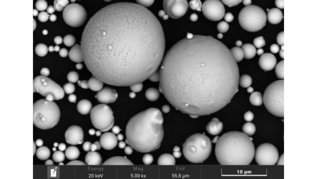
A customised, gas atomised (GA) Ancor AM Ni-free stainless steel (< 25 micron) powder was used in the reported study. This powder was supplied by GKN Hoeganaes Corporation (Cinnaminson, NJ, USA) and was designed for printing with binder jetting with regard to the particle size fraction and the sintering activity. The main powder characteristics and the chemical composition are given in Table 3. Since the material is nickel-free, the amounts of nitrogen (0.349 wt.%) and manganese (11.52 wt.%) are high in order to stabilise the fcc-phase. The gas atomised powder showed the typical spherical morphology (Fig. 6).
In the parameter optimisation study for processing, the following critical parameters were investigated within the BJT process development for the Ni-free SS: recoater parameters (roller speed and rotation), layer thickness and printing temperature. The amount of binder per layer was adjusted in relation to the layer thickness, but always kept at 100% saturation. Curing parameters (temperature and time) were kept constant.
For testing, different specimen geometries were used: transverse rupture strength test bars (TRS-bars) for density measurement and microstructure investigation as well as tensile test bars. For dimensional evaluation, flat pyramids with different width stair steps were used (Fig. 7b). Debinding and sintering were carried out in a vacuum batch sintering furnace. The standard sintering atmosphere was nitrogen. Only in one case, pure hydrogen was tested. After sintering, a defined number of samples were densified using HIP. The as-built samples were investigated in the green state, the sintered state and after HIPing.
![Fig. 7 (a) Green density as a function of layer thickness and print temperature (b) image of a green sample for dimensional control, made from Ni-free stainless steel [2]](http://www.pim-international.com/wp-content/uploads/sites/2/2023/08/fig-07-6-1024x433.jpg)
To optimise the spreading behaviour of the new powder during the re-coating process, the recoater speed and rotation were changed from low to high levels and in different combinations. Results showed that the standard recoater parameters provided by the printer supplier for 316L are also the best choice, with reference to green density and surface defects, for Ni-free stainless steel (25.4 mm per second and 8 revolutions per second). Typical defects such as bottom cracks are not visible for these recoater parameters (Fig. 7b). The investigation of layer thickness and printing temperature revealed that the green density is slightly higher for lower printing temperature and higher layer thickness (Fig. 7a). Based on GKN internal experiments:
- The printing temperature directly affects the infiltration behaviour of the binder agent due to its influence on viscosity and evaporation of the organic-based solvent
- The coating thickness mainly influences the distance the binder agent must infiltrate and how much binder agent (number of droplets) is being shot into the powder bed
Overall, the impact of the investigated printing parameters on the green density is relatively low. In summary, the Ni-free stainless steel powder material acts in a relatively robust manner with regard to the process changes.
The main sintering parameters and the density and nitrogen measurement results are summarised in Table 4. The challenge in sintering Ni-free stainless steel is balancing sintering (diffusion) and solution of nitrogen (fcc-phase stabilisation). These processes work competitively. High amounts of nitrogen promote the fcc-phase, but the fcc-phase shows a lower diffusion coefficient compared to the bcc-phase. Hence, the results show that a high sinter temperature does not directly lead to a higher density (Table 4, compare sinter run 1 vs. sinter run 5a). The main reason for this is a ‘sweet spot’ between sintering and nitrogen pick up.
![Table 4 Summary of results of the sintering experiments conducted [2]](http://www.pim-international.com/wp-content/uploads/sites/2/2023/08/table-04-1024x264.jpg)
Also, the sintering atmosphere has a critical impact on the nitrogen content. Hydrogen strongly reduces the nitrogen level after sintering, but typically improves density. Light microscopy images of samples sintered with sinter run 5a are shown in Fig. 8a. With sinter run 5a, the highest density (7.6 g/cm3), in combination with an adequate nitrogen amount (0.5 to 0.6 wt.%), was achieved. The porosity was still visible with a high number of larger irregular and interconnected pores. Furthermore, the etched cross-sections (Fig. 8a) reveal that the microstructure consisted of fcc-phase and a high amount of bcc-phase (i.e., like a ‘Duplex’-steel). Overall, the fcc-phase is not fully stabilised.
![Fig. 8 After sintering: (a) Light microscope image of an etched sample (sinter run 5a; 1270°C; 100% N2) and (b) after HIP, sinter run 5b; 1270°C; 100% N2) [2]](http://www.pim-international.com/wp-content/uploads/sites/2/2023/08/fig-08-4-1024x374.jpg)
To reduce the remaining porosity, HIP post-processing was carried out. Three main effects were visible in the microstructure after HIP treatment (Fig. 8b). Firstly, the porosity was reduced. This effect is also shown by the Archimedes density measurements (Table 4, sinter run 5b). The reduction of pore size is the main benefit of HIP processing, the remaining pores being small and spherical. This condition was perfect for post-processing, such as polishing. Secondly, the amount of ferrite was reduced and the ferrite islands were less connected. Nevertheless, the microstructure was still not fully austenitic after the HIP process.
Possibilities to increase the fcc-phase content are to reduce the sintering temperature to enhance nitrogen solubility, use of a longer holding time at a lower temperature before the sintering soak temperature, and additional heat treatment after sintering. All of these methods help increase the nitrogen pick-up, but can decrease the sintering activity due to the absence of the bcc-phase.
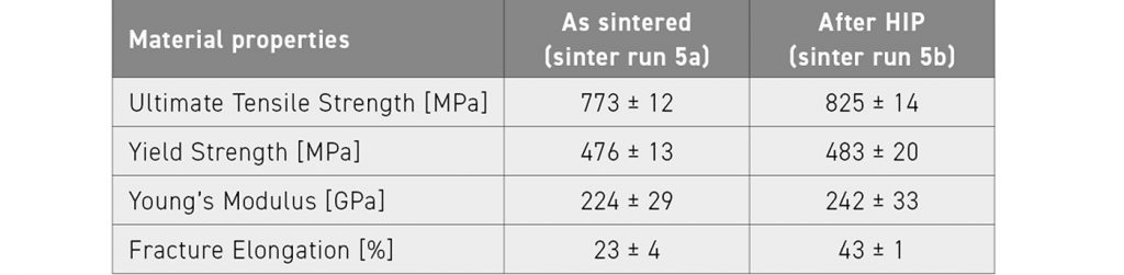
Thirdly, precipitates on grain boundaries are dissolved. It is assumed that these precipitates were chromium-nitrides (Cr2N). The precipitates are removed during the HIP process by dissolving nitrogen into the matrix and stabilising the fcc-phase. Tensile tests carried out indicated that the elongation to fracture was nearly doubled and the ultimate tensile strength and the yield strength were also slightly improved by the HIP treatment (Table 5). These effects are assumed to be caused by the dissolution of the chromium nitrides, increased fcc-phase content and reduced porosity. An advanced microstructural investigation is the subject of further investigation and will be published by this research team in future studies.
The main task for austenitic stainless steels is to provide good resistance against electrochemical corrosion. The Ni-free stainless steel must fulfil this task without nickel to avoid nickel allergy. To examine the corrosion behaviour, the salt spray test was used. Fig. 9 shows two images of tested tensile samples after the salt spray test. The optical results differ significantly. The as-sintered state shows critical corrosion on the whole surface (Fig. 9a), whereas the HIPed samples show almost no corrosion (Fig. 9b). Some corrosion marks are visible in the fixture area (Fig. 9b), but this could be caused by an electrolyte accumulation in this area. The HIP process significantly improves corrosion resistance. It is assumed that the improved density and the dissolution of chromium nitride are the reasons for this. Pores can cause an electrolyte accumulation and, hence, can cause strong and fast pitting corrosion.
![Fig. 9 Ni-free stainless steel samples after 72 h salt spray test; a) samples as-sintered (sinter run 5), b) samples after HIP processing (sinter run 5 + HIP) [2]](http://www.pim-international.com/wp-content/uploads/sites/2/2023/08/fig-09-4-1024x424.jpg)
Chromium nitride formation at the grain boundaries leads to a local depletion of chromium, followed by an insufficient passivation layer on the surface. Without a passivation layer (chromium oxide), the material is not protected against corrosion.
Near surface cross-sections reveal that the surface area (~100 μm) consists mainly of bcc-phase after HIP processing. Steel grades with mainly bcc-phase have a lower corrosion resistance compared to steels with fcc-phase lattice (austenite). After salt spray testing, this high amount of bcc-phase could be a reason for higher surface activity and the visible discolouration (slight corrosion). During HIP processing, the process gas was argon. This absence of nitrogen at high temperatures causes nitrogen depletion in the near surface areas, which could be reduced by using nitrogen as the process gas during the HIP process.
The authors have concluded that the nickel-free stainless-steel material and BJT process route developed by GKN is a reasonable choice for serial production of wearables or jewellery with constant skin contact to avoid any hypersensitivity reaction due to nickel release. Additionally, the HIPed surface is well-suited for surface finishing operations such as polishing. Further tests with nitrogen as the process gas during the HIP process will be carried out to test if this further improves the corrosion resistance.
The Binder Jetting of hardmetals: properties and microstructures of commercial powders
Naiara Azurmendi, Asier Lores and Iñigo Agote (TECNALIA, Spain) and Cristina Fernandes and Daniel Figueiredo (PALBIT SA, Portugal) then reported on a study of the Binder Jetting of different hardmetal powders [3].
In recent years, the Additive Manufacturing of cemented carbides has been gaining attention due to the possibility of fabricating complex-shaped parts and new functional designs with reduced lead times. Initially, efforts were concentrated on laser-based AM processes, where the main drawbacks are the limited final density, the presence of microcracks, undesirable phases and brittle complex carbides due to laser-induced overheating. Numerous studies have also been concentrated on sinter-based AM processes. Among such processes, BJT appears to be more promising due to its low-cost, high productivity and fast manufacturing rate that produces stress- and crack-free parts with isotropic properties.
However, the fabrication of good quality WC-Co parts by BJT remains a challenge and further efforts are needed in order to implement this approach. The aim of the reported study was to shed light on the selection of the most suitable commercially-available hardmetal powder for Binder Jetting technology. With this objective, two different plasma spheroidised WC-12%Co powder grades have been extensively characterised and evaluated in terms of printability. In addition, the final properties obtained (density, shrinkage, microstructure and hardness) at different sintering temperatures have been compared and correlated to the starting raw material.
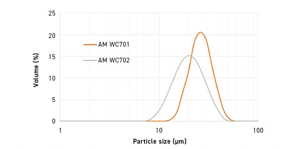
In the presented study, two plasma spheroidised WC-12%Co powder grades provided by Global Tungsten & Powders Corp. (AM WC701 and AM WC702) were used. The graphical particle size distributions (PSD) of the two powders, as well as the main characteristic values, are shown in Fig. 10. Both powder grades show a typical log-normal distribution with an average particle size of about 28 µm (AM WC701 grade) and 21 µm (AM WC702 grade). AM WC702 grade has a wider size distribution and contains a higher amount of fine particles, compared with AM WC701. This is consistent with SEM analysis, where it can be seen that the AM WC701 grade has a narrower PSD (see Fig. 10 a) and b)). Although larger granules are fundamental to obtaining a good powder flowability and spreadability during the recoating process, the presence of fine particles tends to increase the packing density of the powder and also affects positively the sintering process. As expected, both grades showed mainly highly spherical granules, together with some elongated ones, as a consequence of the plasma spheroidisation process.
In addition, both powders contained internal porosity, which may induce higher shrinkage during the densification process. In both grades, two different particle types were observed. It was possible to identify granules with coarse WC grain size up to about 8 μm with visible intragranular porosity. A higher amount of granules with coarse WC grains was detected in the AM WC702 powder grade.
The formation of these coarse WC grains may be inherent in the fabrication process of the powder, where the material is subjected to a thermal plasma spheroidisation process at high temperatures. Particles with a uniform distribution of fine WC grain sizes of about 0.5-1.5 μm were also observed. In contrast to the AM WC701 grade powder, in the AM WC702 powder a few small particles with W2C columnar grains were detected. The differences in WC grain sizes and the presence of W2C particles suggest that the plasma spheroidisation process parameters may be different for the two powders.
Both grades displayed excellent flowability behaviour, according to the calculated Hausner ratio (Table 6). In contrast, AM WC702 had higher apparent and tap densities, which may benefit the powder bed density in the printing process and decrease subsequent shrinkage during the sintering process.
![Table 6 Powder packing properties and Hausner ratio results for the two hardmetal grades [3]](http://www.pim-international.com/wp-content/uploads/sites/2/2023/08/table-06-1024x153.jpg)
The measured cohesive indices (Fig. 11) ranked both powders as ‘fair’ in all the different tested rotating speeds, indicating their suitability for the Binder Jetting process. Despite the presence of a higher amount of fine particles in the AM WC702 grade, both powders displayed very similar cohesive behaviour.
![Fig. 11 Cohesive indices for powders with different rotation speeds [3]](http://www.pim-international.com/wp-content/uploads/sites/2/2023/08/fig-11-3-1024x654.jpg)
For each powder grade, thirty-two samples (10 x 10 x 5 mm) were binder jetted using a water-based binder. A layer thickness of 50 μm and a binder saturation level of 80% were used to print the parts. Curing was performed at 200°C for 4h to eliminate the binder solvents and solidify the polymeric network. The densities of the as-built green samples were measured geometrically, using a digital calliper and a high precision balance. Both powders showed very good spreadability during the BJT process and the samples obtained had a very good appearance without any visual defect. Measured green part dimensions, as well as green density results, are presented in Table 7. The build process was shown to be highly repeatable and reliable, as demonstrated by the low standard deviations of the green density and dimensions obtained from measuring thirty-two samples. Parts printed with AM WC702 grade had higher green density (2 points higher), which is consistent with the higher packing density results obtained in the powder characterisation step.
![Table 7 Dimensional characterisation and green density results with their standard deviations [3]](http://www.pim-international.com/wp-content/uploads/sites/2/2023/08/table-07-1024x113.jpg)
Green samples were then sintered in a sinter-HIP furnace under 30 bar pressure and a holding time of 1h at two different temperatures: 1455°C and 1480°C, with a previous debinding ramp from 150°C to 550°C at 3°C/min followed by a dwell time of 450 min under a hydrogen atmosphere.
Measured densities as well as calculated shrinkages for both powder grades at the different sintering temperatures are gathered in Table 8. The highest density was achieved with the AM WC702 grade at 1455°C, where near full density was obtained. An increase of the sintering temperature with the AM WC702 grade did not induce higher densification and promoted the appearance of undesired free carbon in the microstructure. For the AM WC701 grade, the best results were obtained at 1480°C, but still some remaining porosity was observed. With regard to shrinkages, as expected, higher shrinkages were observed with AM WC701 at 1480 (25% in X, 24.4% in Y and 25.5% in Z directions), as compared with AM WC702 at 1455°C (23.7%X, 23%Y and 24.4%Z directions).
![Table 8 Density and shrinkage results for the two hardmetal grades at two different sintering temperatures [3]](http://www.pim-international.com/wp-content/uploads/sites/2/2023/08/table-08-1024x224.jpg)
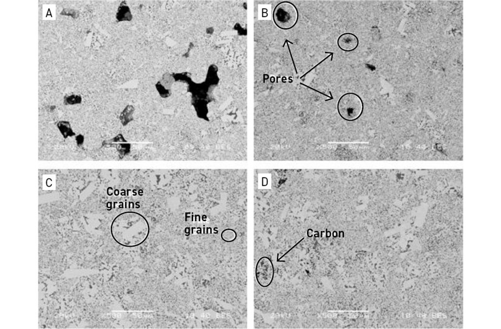
As can be observed in Fig. 12, samples built with both powders showed bimodal distributions of WC grain size, this being strongly linked to the dual distribution observed in the WC grain sizes of the raw materials. Two clearly differentiated areas could be observed in the microstructure: fine-grained areas and the coarse-grained areas (Fig. 12C). In addition, it could be observed that the samples obtained with AM WC702 contained more coarse-grained clusters than samples obtained with AM WC701 powder, consistent with the microstructural analysis results of the powders, where higher amounts of coarse-grained WC granules were observed in the AM WC702 powder.
In the AM WC702-1455 sample, the coarse grains had an average grain size about 4-6 μm (the coarser grains approach about 20 μm) (Fig. 13A) while the carbides in the fine-grained area are in the range of 0.5-2 μm (Fig. 13B).
![Fig. 13 SEM image of the samples printed with the AM WC702 grade and sintered at 1455°C: A) microstructural details B) fine-grained area [3]](http://www.pim-international.com/wp-content/uploads/sites/2/2023/08/fig-13-2-1024x380.jpg)
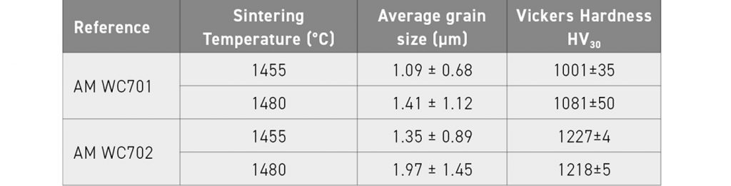
Calculated average grain sizes, together with Vickers hardness data, from the various samples are collected in Table 9. Note that the presence of abnormal grain growth was not included in the grain size measurement. The highest hardness value with the lowest standard deviation of 1227±4 HV30 was measured for AM WC702 sample sintered at 1455°C, which is similar to the hardness value (~1250 HV30) obtained for a standard composition WC-12%Co with a fine/medium grain size. AM WC701 samples showed higher deviations due to the remaining higher porosity observed in the samples. With regard to grain size, as can be observed from the values in the table, the increase in sintering temperature from 1455 to 1480°C promotes grain growth of WC carbide grains.
Development of metallic glasses through hybrid sintering: Binder Jetting & Spark Plasma Sintering (SPS)
Finally, Oriane Baulin, Christophe Reynaud and Simon Robbe (CETIM, Framce) described the development of a hybrid route, comprising BJT and Spark Plasma Sintering (SPS), for the processing of metallic glasses [4].
All beam-based AM techniques, assessed for the processing of metallic glasses, needed a machining step to produce final parts, which can be costly and difficult for these materials. With SPS, only simple geometries can be obtained, such as cylinders, for example. There is no available solution to build dense and fully amorphous parts, with complex geometry. Therefore, it was proposed that Binder Jetting could be a promising process to obtain complex geometry and fully amorphous parts, which avoids a machining step. Combined with SPS, this could be an interesting route for the manufacture of fully dense complex metallic glass parts.
This work presented described the optimisation conducted to process final parts without machining, using BJT for forming and SPS as the densification step. The interactions with carbon residues, coming from the printing step of BJT, have also been highlighted and discussed.
The greatest challenges in this work were:
- Determining if the wettability of the amorphous powder is sufficient to print high resolution parts
- Setting the debinding parameters to remove carbon residues as far as possible, keeping the amorphous character and avoiding crystallisation
- Obtaining amorphous fully dense parts with AMLOY-ZR01 using SPS
- Densifying the samples while keeping the amorphous character of the built parts
The amorphous powder used during this project was the Heraeus grade AMLOY-ZR01, with a particle size distribution between 15 and 45 μm. The chemical composition of this alloy was 70 wt.% Zr, 24 wt.% Cu, 4 wt.% Al, 2 wt.% Nb.
In the BJT process development, after printing, the debinding step was conducted using an air muffle furnace and the pre-sintering process using a vacuum/controlled atmosphere furnace.
The subsequent SPS sintering process employed was as shown in Fig. 14 with Ts (the sintering temperature) being 410°C and ts (the sintering time) being 5 min.
![Fig. 14 SPS cycle [4]](http://www.pim-international.com/wp-content/uploads/sites/2/2023/03/fig-14-1024x532.jpg)
In the BJT process development, a first step to evaluate the interaction between the binder and the amorphous powder was carried out. This consisted of placing a drop of binder on the powder and measuring the time taken to observe the full penetration of the binder into the powder bed. Using a micropipette to calibrate the drops of C20 binder (~0.1 ml), these were deposited onto the AMLOY-ZR01 powder. The same experiment was carried out with 316L powder to compare the time taken for absorption. During these experiments, it appeared that the time for the binder to penetrate the powder was similar for the two powders, indicating that the BJT behaviour would probably be similar and the process parameters for 316L steel BJT could be applied for the metallic glass powder.
The powder was sieved at 45 µm and steamed before the experiments at 80°C for 24 h in air. Then, several BJT tests were carried out, modifying the ‘dark factor’. The dark factor parameter can be considered as a binder saturation level. It is not directly controlled by adjusting the droplet volume, but by adjusting the pattern in which binder is printed onto the powder bed. The printing pattern can be schematised as a chess grid, for which the black cells correspond to the area where ink is deposited. Increasing the dark factor means increasing the number of black cells. A dark factor equal to 3 is typically used for standard materials, such as stainless steels. In the reported experiments, one job was printed with a factor of 3 and another with a factor of 5. The layer thickness was set to 60 μm. The configuration using sieved powder and a dark factor equal to 5 gave the best results in terms of mechanical strength of the green parts and the part definition.
The parts obtained from these jobs, after the depowdering and curing stage (carried out at a temperature of 200°C in air), are shown in Fig. 15. The curing hardened the parts to allow the manual depowdering to proceed. A comparison has been made with the 17-4PH steel grade, to evaluate the definition of the parts against a well-known material in BJT.
![Fig. 15 Photograph of the green parts [4]](http://www.pim-international.com/wp-content/uploads/sites/2/2023/08/fig-15-2-1024x602.jpg)
Several different sample types were produced: cylinders, medallions to assess the resolution of the parts and demonstrators used to evaluate the geometric capability. It appeared that the resolution limit was around 0.5 to 0.6 mm and the definition of the parts was very good. Dimensional checks with a digital microscope were also carried out and no significant differences were apparent, in relation to the printing orientation.
The cylinders were used to measure the green density of the parts from the two jobs through dimensional measurements. The green density was evaluated as an average of the green density measured on 13 parts per job. The results give the following results: 51.5 % as green density for job with dark factor 3 and 52.7% as the green density for the dark factor 5.
In the debinding studies, a first step was carried out according to the classic recipe used for steels: under air with a heating ramp of 20 min from ambient temperature to 345°C. Then, an isothermal step at 345°C for 2h was applied. With this thermal cycle, the parts completely exploded and were fully oxidised.
Therefore, a second study was carried out with a lower heating rate to avoid cracking of the part, about one hour to reach the thermal step temperature of 345°C, under argon gas, and the isothermal step at 345°C for 2h, also with an argon atmosphere.
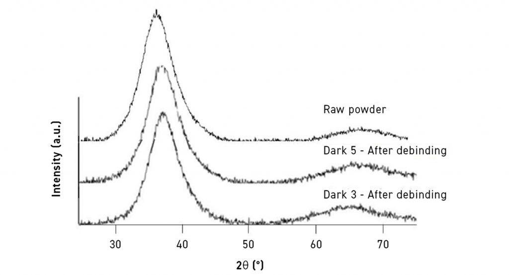
XRD analysis was conducted to investigate the influence of the curing step and debinding step on the amorphous character of the material. According to the results presented in Fig. 16, it appeared that no sign of crystallisation was identified, meaning that the samples were still amorphous at this stage.
In the sintering studies, a first densification step was conducted after the debinding step, at 400°C for 1 min with a 3°C/min-ramp. This temperature was tested, on the basis of previously published work. The samples showed the first signs of consolidation but no real sintered state and a very low mechanical strength.
A second sintering step of 10 min was then applied, improving slightly the mechanical strength but not significantly, and a last one at 430°C for 16 min.
XRD measurements were made to observe if crystallisation occurred for these conditions. The results of this analysis are presented in Fig. 17. The mechanical strength of the sample sintered at 430°C for 16 min was still poor but, according to Fig. 17, crystallisation had occurred, meaning that neither time nor temperature could be increased.
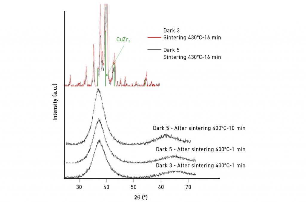
These results demonstrated that no densification could be generated in the sintering furnace with this material and binder. Only a pre-sintered state could be obtained, as the temperature could not be increased due to the crystallisation observed at 430°C.
SPS studies were therefore carried out. To determine the operating point of the process for this alloy, it was necessary to perform parametric optimisation on the raw powder. The first conducted experiment comprised the application of a temperature ramp in order to evaluate the end of sintering. During the SPS experiment, it was possible to determine the end of sintering using the displacement of the plunger. During the sintering step, the displacement of the plunger evolves as the density of the sample increases. At the end of sintering, the plunger no longer moves. This point was obtained at 410°C. The temperature was raised further to 460°C and a mould break was noted at a temperature around 435°C, probably due to an exothermal reaction associated with the crystallisation of the sample.
A final test was conducted at 410°C for 5 min at 100 MPa. Density measurement showed that density of the sample, at 6.68, corresponded to the theoretical maximum density of the material. Image analysis of cross-sections of the material processed under these conditions showed the porosity content to be 0.37% in the worst areas. The observed pores were very fine and exhibited a spherical shape.
Hardness measurements were also made, using a load of 30 kg, and gave 467 HV, which is a little lower than expected and than announced by the material supplier (480 HV5). No crack appeared during the indentation, indicating a good plasticity of the sample. XRD measurements confirmed that no crystallisation had occurred.
The same SPS parameters –410°C, 100 MPa and 5 min – were applied on BJT samples pre-sintered at 400°C for 10 min in an argon atmosphere. Similar behaviour in sintering as for the raw powder was obtained.
A heating step up to a temperature of 460°C was applied to the sample to evaluate the end of the sintering and compare potential differences between raw powders and pre-sintered BJT samples. The end of sintering was apparent at 420°C for the pre-sintered BJT sample, as opposed to 410°C for the raw powder. Full density seems to be more difficult to achieve for pre-sintered samples. Heating was continued to 460°C and no break of the mould was observed. This difference can be explained by the step of pre-sintering inducing structural relaxation. Even if the end of sintering was observed, the mechanical strength of the final sample was still very low and crystallisation was highlighted by XRD measurements.
Two explanations have been proposed in relation to the change of the operating point of SPS: firstly, the presence of carbon residues and secondly, the first thermal applied cycle which corresponds to the debinding step. Carbon measurements were carried out on the samples with a dark factor 3 and a dark factor 5, after the sintering furnace cycle. The carbon measurements indicated 0.1082% and 0.1586% respectively, consistent with the dark factor setting.
Further investigations were carried out using DSC experiments in order to evaluate a potential change in the thermal stability. The results of the DSC experiments are listed in Table 10.
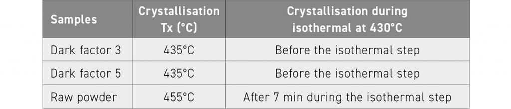
The pre-sintered samples exhibited lower crystallisation temperatures and lower thermal stability as the crystallisation occurred before the isothermal step. Two factors could explain this difference: firstly, a thermal cycle had already been applied to these samples and, secondly, carbon residues were still contained in the samples. To highlight which factor had the greater impact, an enhanced debinding step was applied in processing samples for 5 h at 350°C. The purpose of this was to eliminate a higher quantity of residues and to observe a potential decrease of the thermal stability as the time to process the sample was higher. The tests with enhanced debinding were carried out on the job 2 sample (dark factor 5, higher carbon content). The results, in terms of carbon content measurements after the debinding, was 0.1063%, instead of 0.1586 % for the 2 h debinding, thus proving the beneficial influence of the enhanced debinding.
New DSC experiments were conducted to establish the thermal stability of the sample. It appears that the thermal stability was similar to the previous samples, meaning that the influence of the structural relaxation induced by the debinding step is less relevant than the presence of carbon residues.
In conclusion, the successes arising from the reported study were highlighted:
- Firstly, fully dense, amorphous samples with simple geometry have been processed using raw powder and SPS only
- Secondly, the proper parameters for the printing in BJT for AMLOY- ZR01 powder have been determined to obtain parts with high resolution: steaming conditions, printing parameters, binder deposition, curing step
- After a few trials and, as expected, the densification cannot be achieved with only BJT. A pre-sintering step with BJT process was combined with SPS to generate fully dense parts. This point is still in progress as the carbon residues prevent a good mechanical strength in the parts and the crystallisation resistance of the pre-sintered samples is lower
On the basis of these results, several avenues of further study can be defined. For example, in relation to the enhanced debinding cycle which contributes to a delay in crystallisation, the proper conditions, time and temperature, need to be fully defined. A change of binder to one with better deterioration at low temperature could also be studied.
The alloy composition is also a key feature for future study; using a more stable composition could be a good option to investigate hybrid densification processes.
The next step of the development will be to adjust the process to complex parts in SPS, in order to densify and produce complex geometries with this hybrid technique.
Author and contacts
Dr David Whittaker
Tel: +44 1902 338498
[email protected]
[1] Matteo Zanon, Kymera International, USA
[email protected]
[2] Lennart Hecker, GKN Sinter Metals GmbH, Germany
[email protected]
[3] Naiara Azurmendi, TECNALIA, Spain
[email protected]
[4] Oriane Baulin, Centre Technique des Industries Mécaniques (CETIM), France
[email protected]
References
[1] Metal Binder-Jetting of Aluminium-Based Alloys, Matteo Zanon et al. As presented at the World PM2022 Congress, October 9–13, 2022, and published in the proceedings by the European Powder Metallurgy Association (EPMA)
[2] Investigation Of Printing, Sintering, And HIP-processing Of Nickel-Free Stainless-Steel For Binder Jetting, Lennart Hecker et al. As presented at the World PM2022 Congress, October 9–13, 2022, and published in the proceedings by the European Powder Metallurgy Association (EPMA)
[3] Binder Jetting Of Hardmetals: A Comparative Study Of Microstructures And Properties Of Different Commercial Powders, Naiara Azurmendi et al. As presented at the World PM2022 Congress, October 9–13, 2022, and published in the proceedings by the European Powder Metallurgy Association (EPMA)
[4] Development Of Metallic Glasses Through Hybrid Sintering Processes: Metal Binder Jetting (BJT) & Spark Plasma Sintering (SPS), Oriane Baulin et al. As presented at the World PM2022 Congress, October 9–13, 2022, and published in the proceedings by the European Powder Metallurgy Association (EPMA)
World PM2022 Proceedings
The full proceedings of the World PM2022 Congress are available to purchase from the European Powder Metallurgy Association.
www.epma.com


