Headmade Materials and Cold Metal Fusion: An innovative approach to sinter-based Additive Manufacturing
In recent years there has been a surge in interest in sinter-based metal Additive Manufacturing, with many of these technologies adapting the materials used in Metal Injection Molding. Whilst Binder Jetting (BJT) and Material Extrusion (MEX) processes lead the field in terms of market penetration, sometimes something radically different comes along. This is certainly the case with Germany's Headmade Materials, whose Cold Metal Fusion (CMF) AM process takes a completely new approach. Dr Georg Schlieper visited the company and reports for PIM International on the company and its technology. [First published in PIM International Vol. 15 No. 4, Dec 2021 | 15 minute read | View on Issuu | Download PDF]

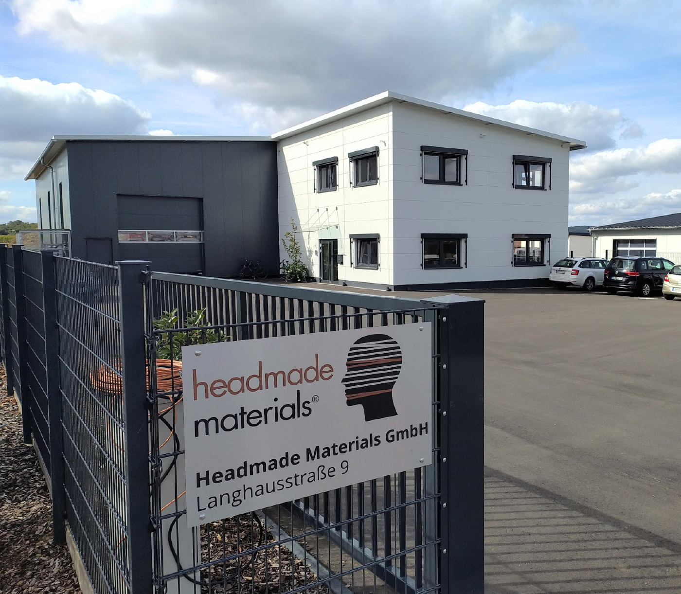
Headmade Materials GmbH is a start-up based in northern Bavaria, Germany. Founded at the beginning of 2019 by Christian Staudigel and Christian Fischer, the inventors of the unique Cold Metal Fusion process, the company is backed with VC-funding from btov’s Industrial Technologies fund, and currently employs thirteen. In 2020, it moved into its current premises in Unterpleichfeld, a small town near Würzburg.
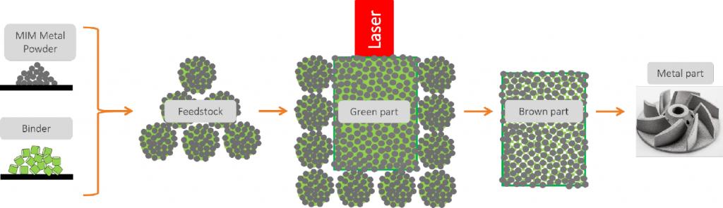
The Cold Metal Fusion (CMF) process is, in part, a radical departure from other sinter-based AM processes, although the metal powders and debinding and sinter processes that are used will be familiar. The process uses a feedstock made of a thermoplastic binder filled with metal powder, developed by Staudigel and Fischer, that is processed on commercially available Laser Beam Powder Bed Fusion (PBF-LB) AM machines for polymers to create green parts.

The seed for the invention was planted when the pair became friends while studying mechanical engineering, with a focus on polymer engineering, at the University of Applied Sciences in Stuttgart. After completing their master’s degrees, they went on to study at the SKZ Kunststoffzentrum research institute in Würzburg. One research topic the pair studied at SKZ was the processing of highly filled polymers using Additive Manufacturing. In order to produce flame-resistant or electrically conductive plastics, the materials are filled with certain substances. The higher the degree of filling, the stronger the effect of the filler material on the material’s properties.
During this work, Staudigel and Fischer came up with the idea of creating green AM parts with metal powder-filled polymers before sintering them into finished components, as in the Metal Injection Moulding process. Initially, they used filaments filled with metal powder using Fused Filament Fabrication (FFF), a Material Extrusion (MEX) process. Based on their experience with FFF, the pair learned more about metal powders and the requirements for the binder. Finally, they developed a micro-granulate that could be processed on polymer PBF-LB machines.
The Cold Metal Fusion process
As with many sinter-based Additive Manufacturing process, Cold Metal Fusion uses the same metal powders as MIM. Headmade Materials’s proprietary binder system is used to produce a micro-granulate that behaves like a highly filled polymer and, as such, can be processed like a plastic feedstock in the polymer PBF-LB process, with the difference being that the manufacturing temperature and energy is much lower than for plastics such as polyamide.

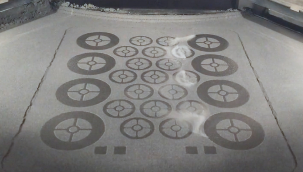
At the beginning of a build, a layer of the ‘powdered’ polymer-metal feedstock is first spread over the base plate in the build chamber of the polymer PBF-LB machine. The green parts are not built directly onto the build plate, as in metal PBF-LB, but onto this initial powder layer. A laser beam selectively melts the polymer element of the feedstock with the effect that the feedstock granules bond. Once the first layer is created, the base plate is lowered by a layer thickness and the next layer of powder applied with a blade or roller. The next layer is then selectively melted with the laser beam (see Figs. 2 and 3). In this way, the green parts are built up layer by layer. The temperatures in the build space do not exceed 80°C.
The usual layer thickness for additively manufacturing with CMF feedstock is 0.1 mm, significantly larger than with other AM processes. This leads to a comparatively higher build speed while still allowing parts to be additively manufactured at a suitably high resolution for many technical applications.
In contrast to metal PBF-LB, the green parts produced by Cold Metal Fusion do not require support structures during the PBF-LB process itself; support is provided by the surrounding powder. This means that the green parts do not have to be laboriously separated from support structures and the build plate during post-processing. This also means that the entire volume of the build chamber can be used for parts, as no space is taken up by supports (Fig. 4). Up to several hundred green parts can be manufactured in a single build job, depending on the component size and the size of the build chamber.

Thanks to these advantages, Staudigel stated that production volumes of up to 100,000 parts per year can be possible and economically viable with CMF. In this way, it is believed that this technology can close the gap between those Additive Manufacturing processes that are attractive for single parts and low build quantities, such as in common in metal PBF-LB, and the MIM process, which is primarily used for large-to-very large production volumes.

Regardless of the process used, Additive Manufacturing offers unprecedented design freedom that is far superior to the MIM process. In principle, the size of CMF green parts is limited only by the size of the build space of the AM machine, but, in most cases, it is the sintering step that is the limiting process. Even with this in mind, the CMF process still allows the production of much larger components than the MIM process.
The advantages of high green strength
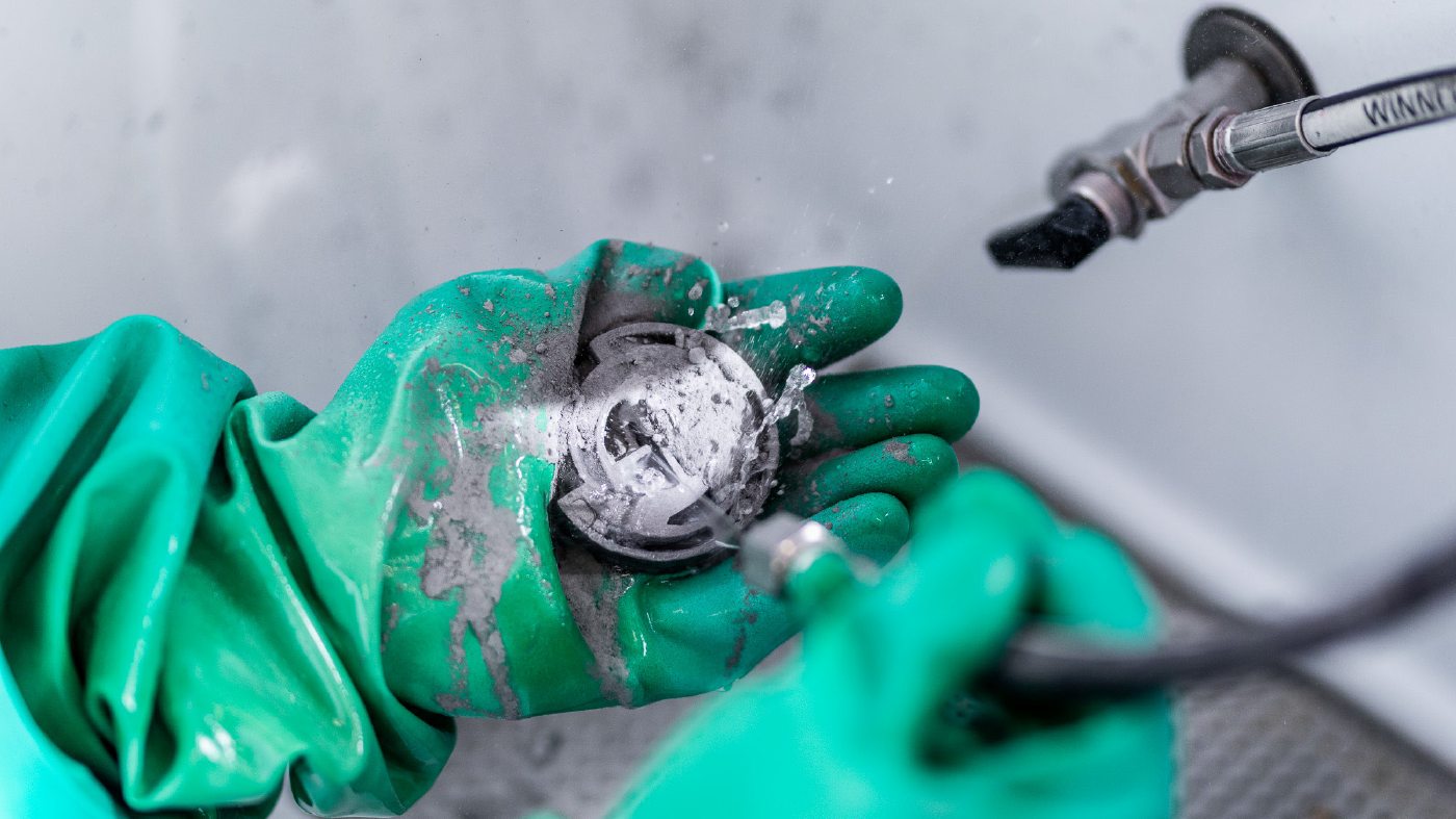
A crucial feature is the high strength of green parts produced by CMF (Fig. 5). This strength makes it possible to depowder a build with water and thereby facilitates automatic depowdering (Fig. 6). Unmelted feedstock can be recycled and reused for the next build. It is even possible to perform machining operations on the green parts and to significantly improve the surface quality via common post-processing steps such as vibratory grinding and blasting. There is also an option to assemble two or more green CMF parts via sinter joining – a proven technique from the MIM industry.
Debinding and sintering
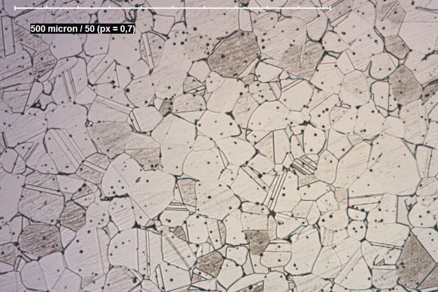
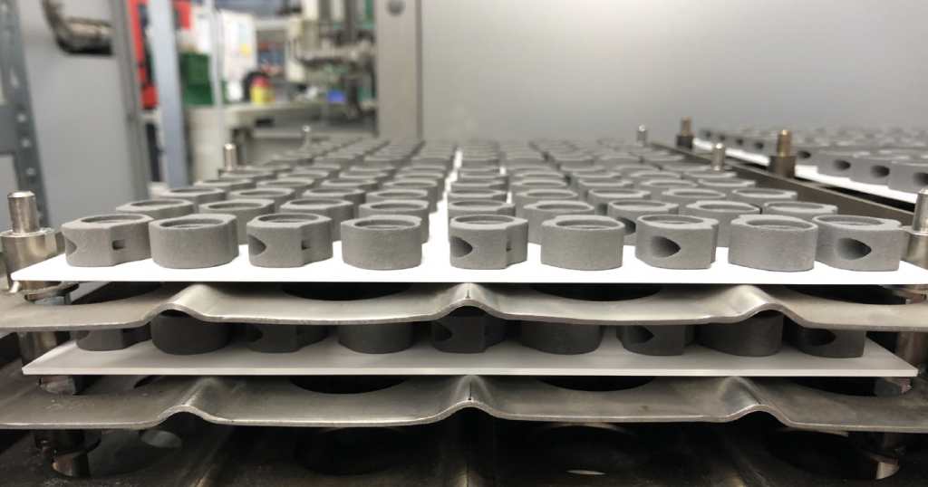
The internal structure of the green CMF parts is very similar to that of green parts produced by MIM and, as with MIM parts, they are further processed by initial debinding in a solvent and then second stage thermal debinding and sintering. The binder content of the CMF feedstock is, however, slightly lower than that of typical MIM feedstocks, thus shrinkage during sintering is also slightly lower than with MIM parts. The shrinkage in the X, Y and Z directions is much the same, which is not the case with all sinter-based Additive Manufacturing processes; this enables a high dimensional accuracy. In the sintered state, the density, microstructure and material properties are identical to those of MIM components (Fig. 7).
Metal powder specifications and material availability
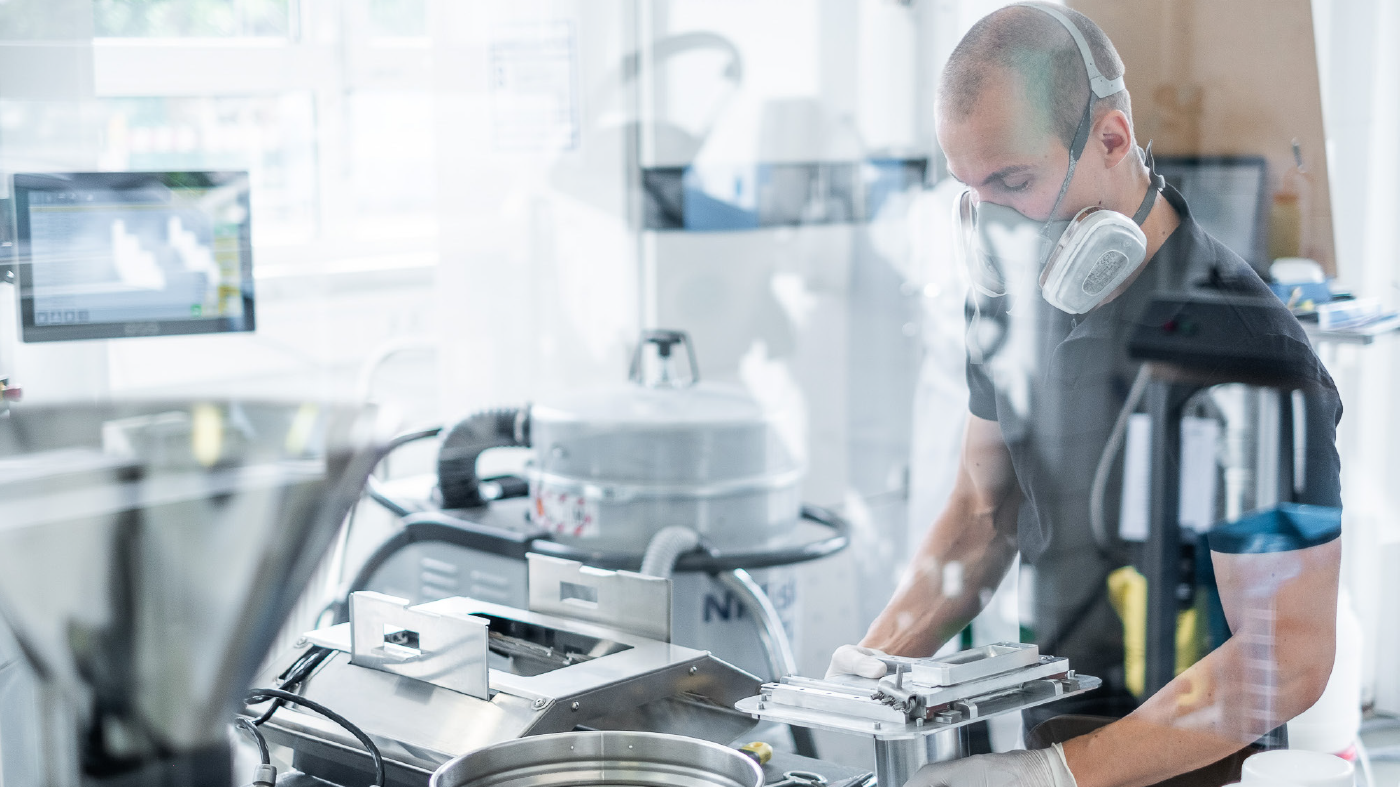
Metal powders with particle sizes from 5–25 μm are best suited for the CMF process, but coarser and finer powders have also been successfully processed. The flowability of the metal powder itself is not of high importance, as integrating the powder into the CMF feedstock adds a certain level of flowability. Both pure and pre-alloyed metal powders, as well as metal powder blends, can be used as the raw material. Since the metal powder is agglomerated in the CMF feedstock, there are fewer safety issues in a CMF manufacturing facility than with other AM processes that work with exposed powder; when processed into CMF feedstock, the powder particles are fully enclosed by the binder and are, therefore, far less sensitive to oxidation and moisture, which is particularly advantageous for such oxygen-affine materials as titanium. Nevertheless, respiratory protection is required when working with CMF feedstock (Fig. 8).
As with MIM, the potential range of materials that can be processed by CMF is considerably greater than with the conventional metal PBF-LB process, although only a select range of alloys have been qualified to date. In principle, all materials that can be processed via MIM can also be processed via CMF. So far, in addition to 316L stainless steel and Ti6Al4V, Headmade Materials offers a cobalt-chromium alloy, pure titanium grade 1, and a tungsten alloy. 17-4PH stainless steel will be released at the end of 2021, and tool steels, copper alloy, aluminium and a superalloy are also under development.
Headmade has yet to attempt the processing of ceramic materials using CMF. “We are focusing on metals for the time being, because we see a larger market there in the near term,” explained Staudigel. “Ceramic powders are considerably finer than metal powders. As this requires additional development work, this is a lower priority for the time being.”
Comparisons with metal PBF-LB
Staudigel admits that metal PBF-LB has its strengths in comparison to sinter-based processes, particularly when it comes to the production of parts in small quantities. He also stated that metal PBF-LB is significantly more advanced than sinter-based AM processes in terms of process simulation, and in the ability to manufacture very fine cooling channels and remove the powder from them; sinter-based processes are at a disadvantage here.
The issue of density was also raised, particularly in relation to tool inserts with internal cooling channels. The surface of these tools has to be absolutely pore-free, because even the smallest pores become visible on a polished surface and lead to the rejection of a component. “It is very difficult to produce tool steels to an entirely pore-free structure using sinter-based processes. For high-quality components, therefore, an additional Hot Isostatic Press (HIP) operation is usually necessary after sintering,” stated Staudigel.
Application development
Application development can either be carried out in-house, in close cooperation with the customer, or at a customer’s own facility. So far, the focus has been on components made of 316L, tungsten heavy metal and Ti6Al4V.
Bathroom components
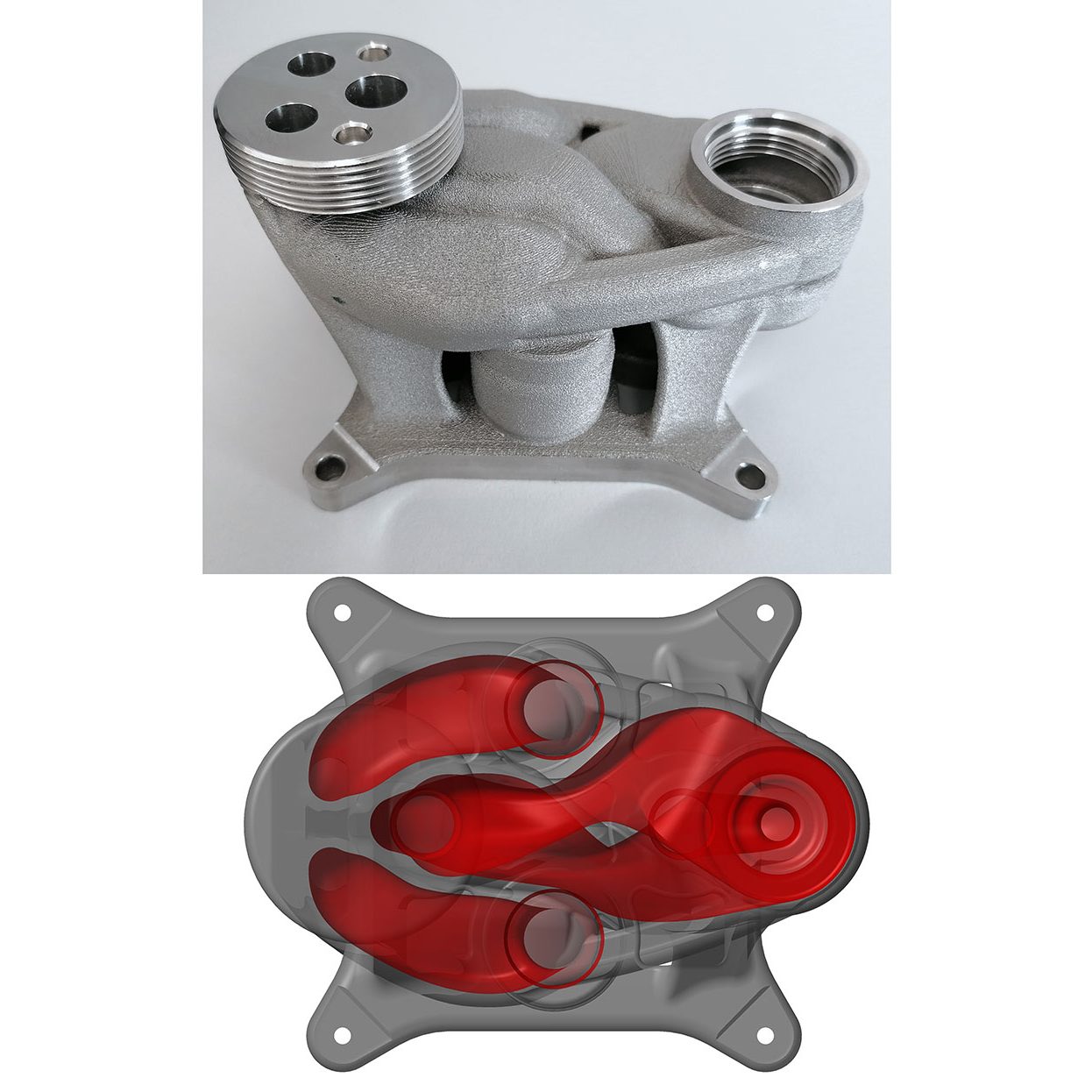
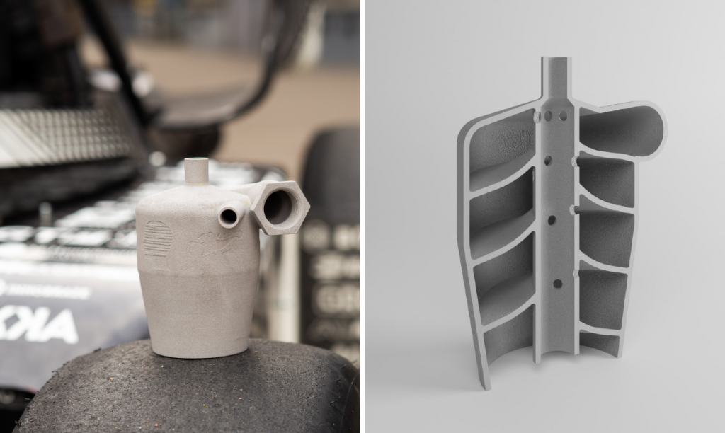
One customer is Hansgrohe SE, a specialist in high-quality bathroom fittings, which is showing great interest in CMF technology because the process enables the production of complex components with integrated water channels. An example of the type of part Hansgrohe is investigating for CMF, a component for a water fitting designed for use in hotels, is shown in Fig. 9. Here, the channels are designed in such a way that flowing water produces as little noise as possible; in this way, hotel guests are shielded against plumbing noises from neighbouring rooms.
The bicycle industry
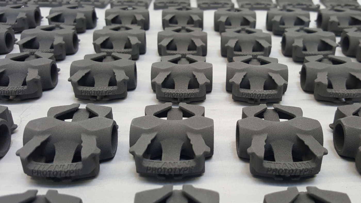
In order to apply its CMF technology to titanium and titanium alloys, Headmade has entered into a close cooperation with Element22 GmbH, a leading manufacturer of titanium MIM products based in Kiel, Germany. The first applications being prepared for market are components for the bicycle industry. This industry is showing great interest in the potential for complex, lightweight titanium components for bicycle frames, pedal cranks and clipless pedals (Fig. 10).
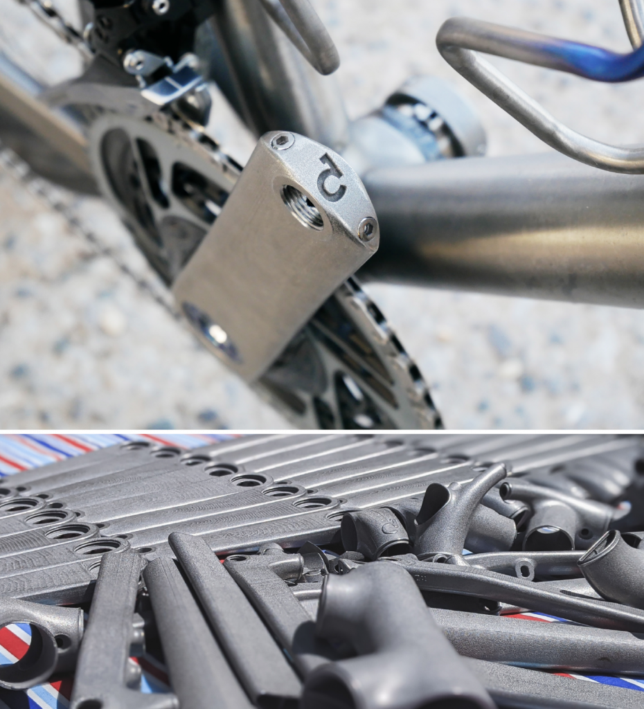
A number of bike frame builders are exploring titanium products made with Cold Metal Fusion technology, thanks to its cost advantages and the better, more uniform surface that can be created. A few thousand bike frame components are expected to be manufactured with CMF technology in the coming year.
Motorsport
The oil separator shown in Fig. 11 is used in the Stallardo ’21 race car, produced for the Formula Student racing team Rennstall Esslingen. The Ti6Al4V part features a complex inner helix. The connection thread was additively manufactured as a separate part and joined with the oil separator in the sintering process. Further applications are under development in areas including medical technology.
Heavy metal components
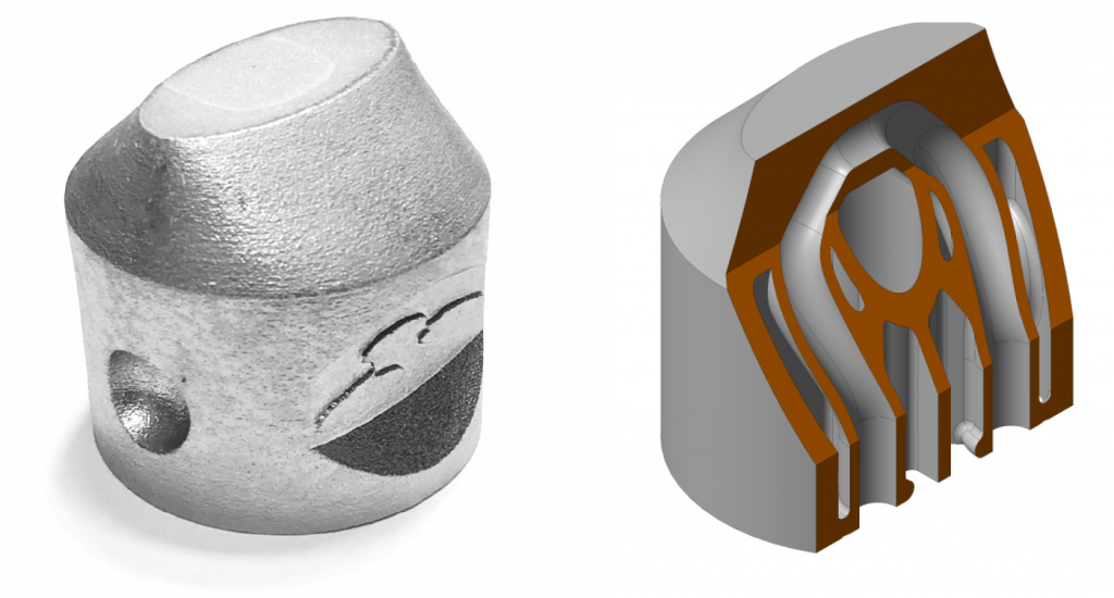
In cooperation with Plansee SE in Reutte, Austria, Headmade has also developed a component made of a heavy metal alloy that contains internal cooling channels (Fig. 12). The part measures about 50 x 50 x 50 mm and weighs 1.2 kg.
Design guidelines
Although Additive Manufacturing offers an unprecedented freedom of design, CMF technology, like all industrial manufacturing processes, requires process-oriented product design. For this purpose, Headmade Materials has created a guide with instructions for the design of CMF parts, incorporating experiences from both polymer PBF-LB and MIM technologies into the guidelines.
The limiting factor for CMF technology is less the build process for green parts – which can additively manufacture almost every structure possible in a polymer PBF-LB machine – but the required debinding and sintering steps that follow, and which impose strong limits on possible part designs.
It should always be borne in mind that these parts go through a relatively unstable state in the sintering phase, where gravity can have an unwelcome influence. This critical stage is the main limiting factor. Headmade is, together with partners, working on simulations to make trial-and-error iterations more predictable.
Dimensional tolerances are generally given as +/-0.3 mm for larger and heavier parts. Depending on the part geometry, dimensional tolerances of up to +/-0.1 mm are also possible.
Flat surfaces and part positioning
The first fundamental principle for the design of CMF parts is that they should have a flat surface on which they rest during sintering. Otherwise, there is a risk that the part will be deformed on the sinter plate and warping will occur due to a part’s own weight. If a flat surface is not possible, distortion can possibly be counteracted by a sinter support adapted to the geometry of the part – however such solutions add cost.
In addition, parts should be positioned during sintering in such a way that the largest masses rest on the sinter plate. Overhanging parts are particularly susceptible to distortion and may need to be supported during sintering.
Wall thickness
Wall thicknesses should be between 1 and 10 mm; with wall thicknesses above 10 mm, it is difficult and time consuming to completely debind the green parts. On the other hand, it is not necessary to design a uniform wall thickness, as is recommended with MIM. Free-standing walls that are connected to the base body on one side only should be at least 2 mm thick and no longer than 20 mm tall, otherwise the risk of distortion increases.
Through holes and threads
Through holes should have a diameter of between 1 and 20 mm. Larger diameters are possible, but require additional measures – for example, a larger wall thickness in order to improve the stability, or less weight above the bore. Because of the layer-by-layer process, with manufacturing steps of 0.1 mm, circular holes should preferably be aligned vertically. Horizontal holes usually have to be reworked. Through holes are easier to depowder than blind holes.
Threads can be additively manufactured up to a minimum size of M4. When manufacturing, the thread should be oriented in the Z direction. Finer threads should be recut to ensure a good fit.
Headmade’s business strategy
“The focus of our business activities lies on the production and marketing of the feedstock for Cold Metal Fusion,” explained Staudigel. “We are not a manufacturer of production equipment, but provide our customers with the material and know-how for processing the feedstock into high-quality components.”
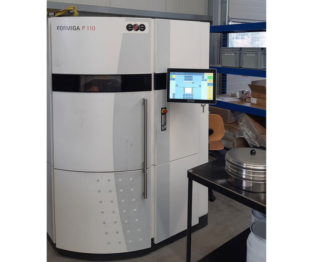
To demonstrate the capabilities of the process and to get new customers to a point from which they can manufacture their applications themselves, Headmade Materials has an in-house application centre with all the necessary equipment for part design and optimisation, building, debinding and sintering. Fig. 13 shows a commercial polymer PBF-LB machine which is used at Headmade Materials.
For understandable reasons, the equipment and technology used to produce the feedstock is not shown to the public. There are three polymer PBF-LB machines for production of parts. Solvent debinding takes place in a commercially available system and a vacuum furnace is available for sintering. In case of larger quantities, external partners with higher sintering capacities are involved in the production process (Fig. 14).
One of the first manufacturers of MIM parts to have implemented Cold Metal Fusion in its production was MIMplus Technologies, Ispringen, Germany. For MIMplus’ decision in favour of CMF technology, the high component quality, cost effectiveness and easy integration into the company’s production were of particular importance.
Christian Staudigel believes that Powder Metallurgy and MIM companies considering the implementation of AM in-house usually need to change their business model, because most of them are set up for mass production. AM, on the other hand, is not particularly economical for mass production, but for smaller quantities. Fortunately, however, the trend today is towards smaller quantities and a greater diversity of variants of industrial products.
Marius Geldner, CFO of Headmade Materials, stated, “A lot of work is still needed to bring the benefits of our process closer to customers. Often, a design change is necessary to take full advantage of Additive Manufacturing.”
“For customers who have no experience of sintering, it is not easy to select the appropriate systems from the wide range of sintering furnaces that are available, as they do not know exactly what requirements they have to meet,” explained Staudigel. “We at Headmade Materials help them overcome this hurdle.”
The company is striving to make its process known to experts through presentations at symposia and through participation in technical exhibitions such as those at Fraunhofer IFAM, the Hagen Symposium and Formnext. In addition, the company cooperates closely with the leading manufacturers of polymer PBF-LB machines. These company’s customers are often interested in setting up a production line for metal AM parts in addition to plastic ones. Furthermore, cooperation is being developed with the manufacturers of MIM sintering furnaces so that they can develop tailor-made solutions for CMF.
Outlook
In the coming years, Staudigel believes that the most important task for his company is the expansion of feedstock production capabilities and the diversification of the material portfolio in close cooperation with customers and their needs.
As the investment in a polymer PBF-LB machine for use with the CMF process is comparatively low, and the manufacturing speed is higher than is possible with many other metal AM processes, the cost-effectiveness of this step is attractive. Staudigel, therefore, expects that the CMF process will soon penetrate new markets that are currently still closed to Additive Manufacturing for cost reasons. The first steps have been taken in the bicycle applications sector, and more will follow.
Author
Georg Schlieper
Harscheidweg 89
D-45149 Essen
Germany
[email protected]
Contact
Christian Staudigel
Headmade Materials GmbH
Langhausstrasse 9
D-97294 Unterpleichfeld
Germany
[email protected]