


How build parameters influence the tensile strength of 316L parts produced by Fused Filament Fabrication
In this article, Dr Samuel von Karsa-Wilberforce, Emery Oleochemicals, Germany, and co-authors report on the tensile strength of sintered 316L specimens produced via Fused Filament Fabrication (FFF), a Material Extrusion (MEX)-based Additive Manufacturing process. The parameters studied include printing nozzle temperature, flow percent or extrusion multiplier and nozzle diameter of print head. The 316L feedstock filaments are based on Emery Oleochemicals’ evolutionary binder system, which has been used in MIM for more than thirty years. The partner in the study for debinding, sintering and mechanical testing is CMG Technologies Ltd, UK. [First published in PIM International Vol. 15 No. 3, September 2021 | 10 minute read | View on Issuu | Download PDF]
Widely known metal Additive Manufacturing processes such as Laser Beam Powder Bed Fusion (PBF-LB) are expensive and generally energy intensive [1]. More recently, the Additive Manufacturing of metal parts via Binder Jetting (BJT), typically using MIM grade powders, has also come to the fore. However, metal Binder Jetting machines are usually quite expensive, and the additively manufactured green part may be prone to breakage if not carefully handled. In comparison, Material Extrusion (MEX) processes such as Fused Filament Fabrication (FFF), also known as Fused Deposition Modelling (FDM), are cheap, and the processes’ low energy consumption offers the potential to produce functional metal parts at low cost [2].
FFF machines are more readily available and easier to operate than conventional metal AM machines. Metal FFF uses a highly filled polymeric filament containing more than 90% by weight metal powder to create ‘green’ metal parts, which then go through debinding and sintering steps to produce metal parts that are close to fully dense. The process of using FFF to produce metal parts from sinterable feedstock is described in detail elsewhere [1].

While the economic and technological benefits of producing metal parts via FFF are clear, it is essential to investigate the mechanical properties of the resulting parts in order to select meaningful and suitable application areas. It has been reported that the mechanical properties of FFF plastic parts are highly dependent on the build, or printing, parameters due to the anisotropic nature of the FFF process. Typical build parameters that highly influence the mechanical properties of FFF parts include printing nozzle temperature, z-direction layer thickness, printing speed, print nozzle diameter, extrusion multiplier or flow percent, infill pattern and infill density [3].
To that end, this article reports on the tensile strength of sintered stainless steel specimens produced with 316L feedstock filament via the FFF process at varying printing parameters. Three main printing parameters were investigated: printing nozzle temperature (PNT), flow percent (FL%) and print nozzle diameter (PND). The green 316L stainless steel tensile specimens were produced with feedstock filament containing thermoplastic binder developed by Emery Oleochemicals [4]. The benefits of this binder system include high powder loading capability, excellent green part stability and solvent debinding at low temperature, among others.

Production of 316L stainless steel feedstock filament
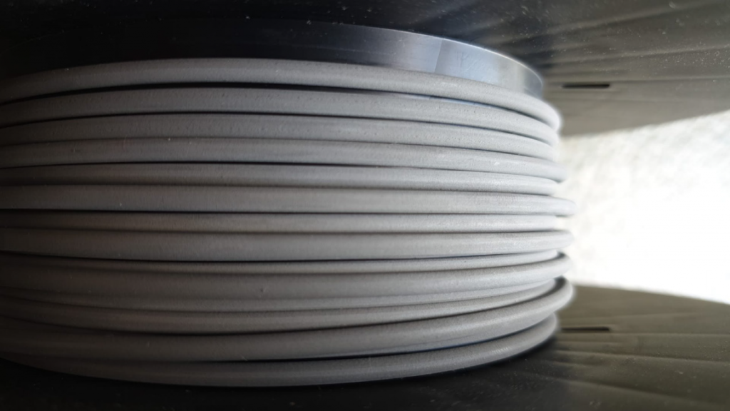
The 316L feedstock granules were compounded using water atomised 316L metal powder with a particle size D90 of approximately 10 μm and the binder components from Emery Oleochemicals. The 316L metal powder was supplied by CMG Technologies Ltd, UK. The binder system mainly consisted of the LOXIOL® 2472 plasticiser, produced exclusively by Emery Oleochemicals, and a polyamide copolymer. The compounded 316L feedstock granules contained more than 90 wt.% 316L metal powder and extruded into 2.85 mm diameter feedstock filaments using a single screw system (Fig. 1). The green density of the 316L feedstock filament was 4.85 g/cm3.
During filament production, the diameter was measured every 1 mm in 2 axes with ± 0.8 μm accuracy. Certified laser measuring devices were used to be sure that the measurement results are reliable.
The Additive Manufacturing of 316L tensile specimens
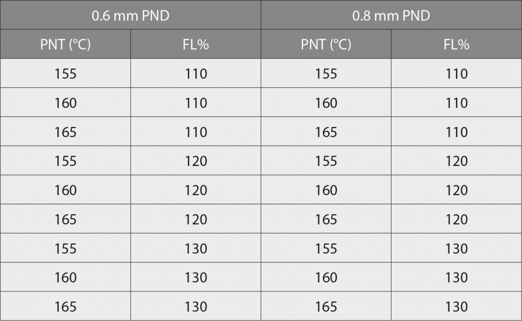
CMG Technologies supplied the STL file for the tensile specimen. The STL file was modified using Cura Additive Manufacturing software to compensate for shrinkage after sintering of approximately 16% in both x/y- and z-directions and to generate the input file for the AM machine, known as the g-code file. The printer-specific g-code file tells the AM machine what actions to perform to build the part. The Epsilon W27 3D printer from BCN3D Technologies, Spain, was employed to produce the green 316L tensile specimens. The build parameters used on the printer were varied as in Table 1, leading to three different PNTs x three different FL%s x two PNDs = 18 settings. The following printing parameters were kept constant at the following values:
- Build speed of 15 mm/s,
- z-direction layer height of 0.3 mm
- Infill density of 100%
- Grid infill pattern
- Bed & closed build room temperature of 25°C
- Material on printing bed is blue painter’s tape
- Wall-infill overlap of 15%
- Two bottom layers and two top layers
- Infill line directions of [0.90]
Post-processing of 316L tensile specimens
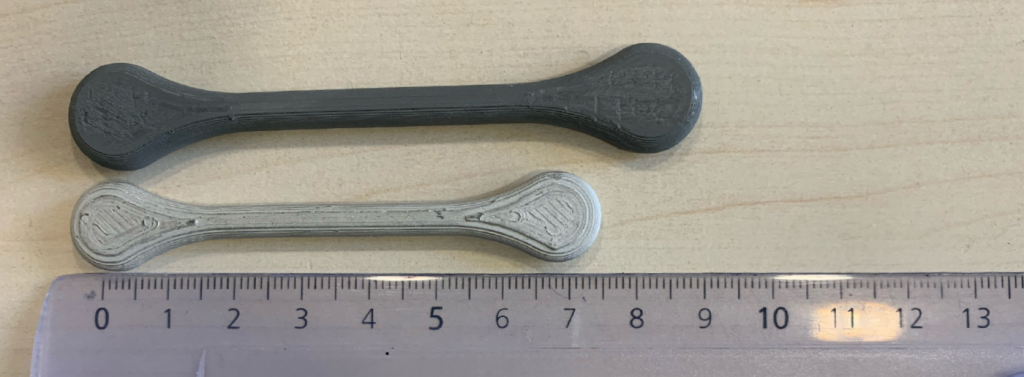
Solvent debinding and sintering of the green tensile specimens were carried out by CMG Technologies. Solvent debinding of the tensile specimens was carried out in acetone at 42°C for approximately eight hours, followed by a 3–5 hour drying time at room temperature to remove the residual acetone. The average binder loss during acetone debinding was approximately 5.4 wt.%. The remaining backbone polymeric binder component was removed at 500–600°C followed by sintering at 1260°C in hydrogen atmosphere for approximately 1 h 30 min holding time to obtain the fully sintered 316L tensile specimens (Fig. 2).
Mechanical testing of sintered 316L tensile specimens
CMG Technologies carried out tensile testing of the sintered specimens. Uniaxial tensile testing of the longitudinal test specimens was executed according to BS EN ISO 6892-1 – 2019 standard to obtain the tensile strength at break. Since the tensile specimens were built in the x/y-direction the data obtained represent the tensile strengths in the x/y-direction only. The tensile strength at break was calculated as a ratio of the force at break and the average nominal cross-sectional area of the tensile specimen, which was calculated to be approximately 16.26 mm2.

Influence of PNT on tensile strength
It has been reported that the mechanical properties of FDM parts vary with varying PNT. Therefore, the PNT, if carefully chosen, can have a positive effect on the mechanical properties. It has been shown that the tensile strength of additively manufactured Polylactide (PLA) specimens improved with increasing PNT [3]. The improvement in tensile strength of PLA at high PNT was attributed to the increase in the fluidity of molten PLA, facilitating the adhesion of the newly deposited PLA strand on the previous one and thus bond width between extruded raster increased which resulted in an improved strength [3].
The results of the tensile testing of the sintered 316L specimens showed a similar result – the tensile strength improved with increasing PNT at all FL% and PND (Fig. 3 and Fig. 4 show this increase for FL% at 120% for both 0.6 mm and 0.8 mm PND).
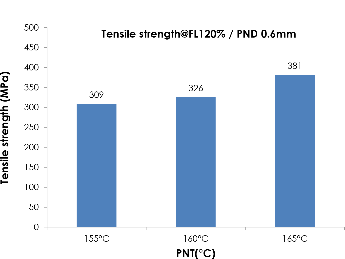
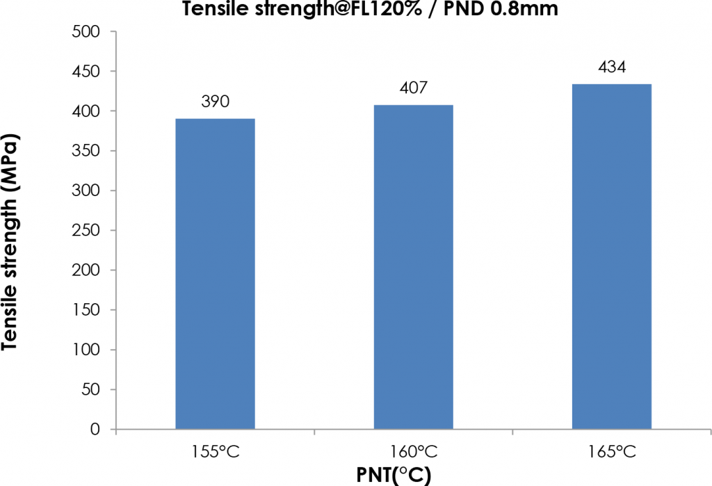
The tensile strength of the sintered part is highly dependent on the bonding strength of layers or extent of layer adhesion in the green part. With increasing PNT, the polymeric binder gains more fluidity and driving force to effectively bond the feedstock layer on the previous layer. This allows for increased interlayer adhesion between the two layers of the green specimens. The increased interlayer adhesion with increasing PNT results in increased tensile strength of the sintered specimen.
Influence of FL% on tensile strength
The extrusion flow rate percent or extrusion multiplier is a parameter in the AM machine’s software that dictates how much material is extruded from the nozzle. By default, this is set to 100% in the machine software. By adjusting this value below or above 100%, part properties such as tensile strength and density can be affected. A very high FL% can lead to over extrusion with clogging, and a very low FL% can lead to under extrusion with voids in part. Within the range of extrusion FL% investigated in this study, that is, from 110-130%, the tensile strength of the sintered 316L specimens increased with increasing extrusion FL% for all PNT and PND. Figs. 5 and 6 show this increase for PNT of 160°C for both 0.6 mm and 0.8 mm PND.
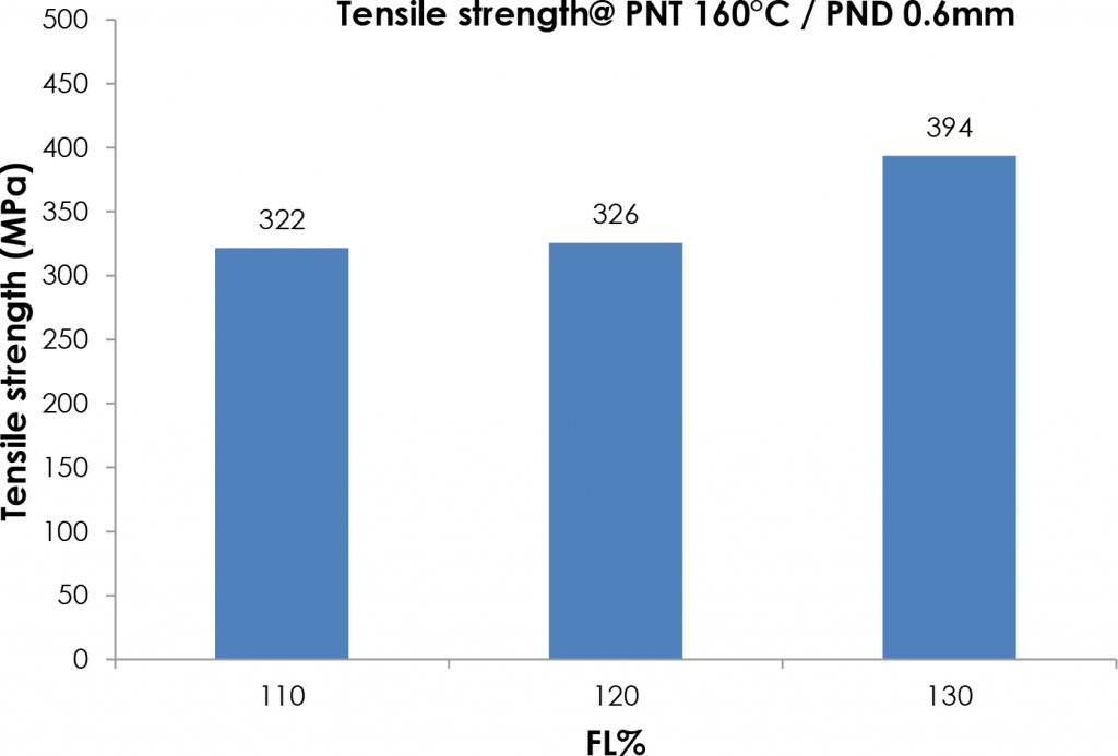
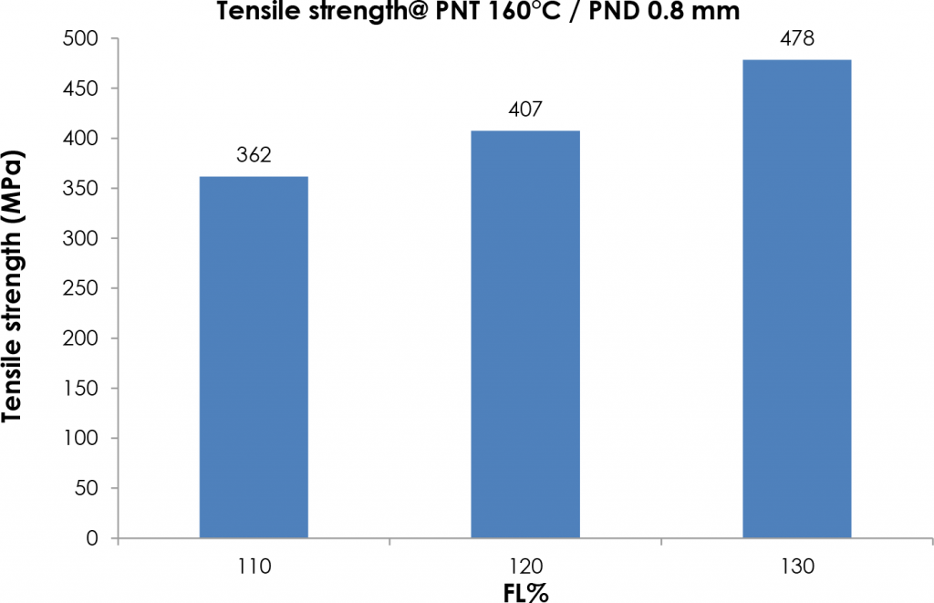
With increasing extrusion FL% more material is deposited to fill voids within the green part which might act as weak points or stress concentrators, leading to a more compact green part. As a result, the tensile strengths of the sintered specimens for parts printed at higher extrusion FL% tend to be higher.
Influence of PND on tensile strength
It has been reported that the mechanical properties of FDM parts can be controlled by varying the PND. By controlling the nozzle size and layer thickness, it is possible to control the air gap between adjacent plastic strands [3]. It was reported that the ultimate tensile strength of PLA parts increased with increasing PND from 0.3 mm to 0.6 mm. This was attributed to a reduction in voids or air gap between adjacent layers with increasing PND, as confirmed by scanning electron microscopy. As the nozzle diameter was increased, the raster became wider. As a result, overlapping and fusion between neighbouring strands occurred [3]. Other authors have attributed this increase in strength with increasing PND to the gravitational force that helps to spread the melted plastic and it is more efficient for large nozzle diameters [3].
The results of the tensile testing of the sintered 316L specimens also showed that the tensile strength increased for the larger PND at all FL% and PNT (Figs. 7 and 8).
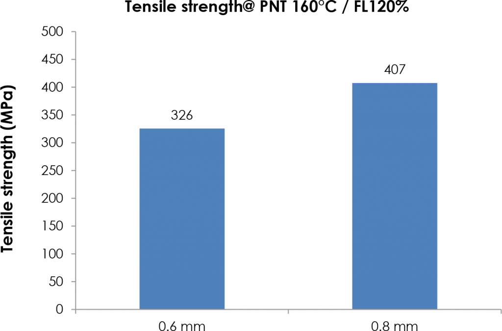
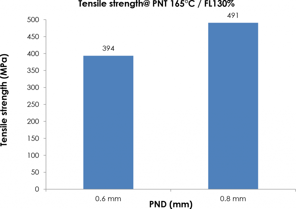
With a larger PND, there are fewer interfaces between strands as single strands are larger and less strands per cm2 are needed, reducing the number of weak points in the part. Moreover, for larger PND, the raster becomes wider, resulting in overlapping between nearby layers and better interlayer adhesion in the green part. This mechanism then translates into high tensile strength of the sintered 316L specimens for parts printed with larger PND.
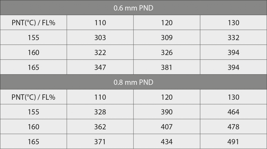
Table 2 summarises all results for influence of PNT, FL% and PND on tensile strength.
Conclusion
In this study, the influence of FFF printing parameters on the tensile strength of sintered 316L specimens is reported. The build parameters investigated include nozzle temperature, extrusion flow percent or extrusion multiplier and nozzle diameter.
The tensile strength at all flow rates and nozzle diameters increased with increasing nozzle temperature. This was attributed to more fluidity and, hence, better interlayer adhesion at higher temperatures. With increasing extrusion flow rate, the tensile strength was found to increase. More voids are filled within the part at higher extrusion flow rates, leading to a more compact structure. The tensile strength at all nozzle temperatures and flow rates were higher for the larger nozzle diameter than the smaller nozzle diameter. Printing with a larger nozzle allows for reduction in the interfaces between strands, thus reducing the number of weak points in part.
The optimisation of the g-code to obtain the best build parameters for the filament is more critical than trying to achieve the best part with the same printer adjustments or g-code using different filaments. Tuning of the printing parameters, be it software or hardware printer parameters, allows for the best use of the filament in question. Additionally, the creation of high-quality green parts of course leads to high quality sintered parts.
Clearly, the FFF build parameters play a vital role in determining the mechanical properties of the sintered part. More studies need to be carried out to investigate the effect of other build parameters, as this will enable selection of the right applications and the tailoring of mechanical properties for the intended application. Potential further work could be the study of the influence of z-layer height, infill structure or pattern, infill line directions, wall-infill overlap% and printing speed on the tensile strength of sintered 316L specimens.
Authors
Dr Samuel von Karsa-Wilberforce and Dr Christian Müller
Emery Oleochemicals GmbH
Paul-Thomas-Strasse 56,
40599 Dusseldorf
Germany
www.emeryoleo.com
[email protected]
Phil Grimmer
CMG Technologies Ltd
Unit 1, Thompson Drive
Base Business Park
Rendlesham, Woodbridge,
Suffolk, IP12 2TZ
UK
[email protected]
References
[1] S v K-Wilberforce, et al., The production and evaluation of alumina sinter supports for Metal Injection Moulding by ceramic Additive Manufacturing, Powder Injection Moulding International Vol 14, No 2 (2020).
[2] B Liu, et al., Creating metal parts by Fused Deposition Modeling and Sintering, Materials Letters 263 (2020).
[3] D Syrlybayev et al., Optimisation of Strength Properties of FDM Printed Parts—A Critical Review, Polymers 13 (2021)
[4] C Mueller et al., Expanding the role for MIM and CIM feedstocks: Evolving PIM binder systems for extrusion and compression moulding, Powder Injection Moulding International 10 (2016).


