


Removing the bottleneck: Automating depowdering for scalable Binder Jetting
Binder Jetting (BJT) continues to attract intense interest as manufacturers search for faster, more economical routes to serial metal part production. Yet despite impressive build speeds and design flexibility, many remain sceptical about Binder Jetting’s readiness for true industrial scale. The bottleneck lies not only in the build process, but in what happens next. Depowdering, still largely manual and labour-intensive, threatens throughput, consistency and safety. In this article, Lea Reineke of Fraunhofer IFAM and Florian Richter from IPH Hannover explain how the QualiJet project aims to change that. [First published in Powder Injection Moulding International Vol. 20 No. 1, Spring 2026 | 10 minute read | View on Issuu | Download PDF]
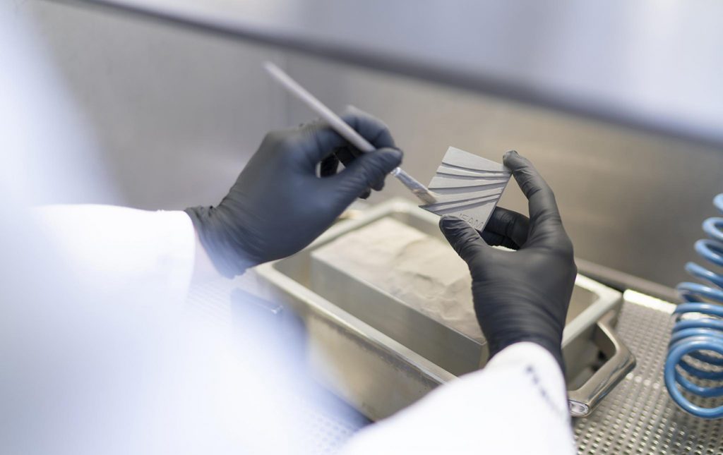
Automated depowdering is a critical enabler for the Additive Manufacturing process known as Binder Jetting (BJT), as it addresses one of the most labour-intensive and limiting steps: removing loose powder from parts after a build. In BJT, parts exit the build chamber surrounded by unbound powder, and manual cleaning is slow and inconsistent, exposing operators to dust hazards. Automation not only reduces labour costs and cycle times, but also improves safety and ensures reproducible, high-quality cleaning results – essential when preparing parts for subsequent debinding, sintering, and finishing steps.
From an industrial perspective, automating depowdering is key to scaling Binder Jetting for serial production. Without it, depowdering remains a bottleneck that can negate many of the throughput and cost advantages of Binder Jetting over conventional manufacturing and other Additive Manufacturing processes. Currently, manual and semi-automated methods are used for depowdering. The long-term goal is to transition to fully automated, robot-assisted systems that integrate with broader production workflows.

The QualiJet research project, led by the Fraunhofer Institute for Manufacturing Technology and Advanced Materials (IFAM) and the Institut für Integrierte Produktion Hannover (IPH), is exploring robotic depowdering with adaptive gripping and computer vision control to handle fragile green parts with complex geometries – addressing challenges that conventional systems struggle to overcome.
Fraunhofer IFAM is one of Europe’s leading independent research institutions in the fields of binder technology, Metal Injection Moulding (MIM) and sinter-based Additive Manufacturing, as well as functional materials, with a mission to develop innovative solutions to key challenges of the future. At its Bremen site, Fraunhofer IFAM has worked for decades on metal BJT research and its transfer to industry.
The IPH Hannover takes a holistic view of production, spanning digitisation, Industry 4.0 and artificial intelligence. IPH adopts an interdisciplinary approach across all areas of the factory: from logistics, which connects processes, to production automation, which digitises and streamlines workflows, and to the optimisation of component manufacturing in process engineering.

The QualiJet project
The QualiJet project was funded by the German Federal Ministry for Economic Affairs and Energy as part of the ‘Industrial Collaborative Research’ programme based on a resolution passed by the German Bundestag. It is run under the supervision of the research association for quality FQS e.V. The project is supported by an advisory board comprising various German companies.
To improve depowdering, the QualiJet project aims to develop a novel automated process that intelligently removes green parts from the powder bed. The system will be demonstrated using metal BJT, but it will also be applicable to Cold Metal Fusion and other two-step Additive Manufacturing processes involving green parts.
The core challenge is the automated gripping of individual, fragile green parts. To address this, the system incorporates a robotic gripper equipped with a camera and computer vision, enabling it to respond flexibly to the specific properties of each part. The gripping system identifies the position and orientation of green parts within the powder bed, determines suitable gripping points, and learns to handle components with varying local strengths. It then exposes, removes, and places the green parts in a safe location.
With the help of an advisory board, eight scenarios were identified that pose a challenge for automatic powder removal (Fig. 2), covering part arrangement, exposure and removal, gripping constraints, size and strength variation, thin walls, and internal channels.
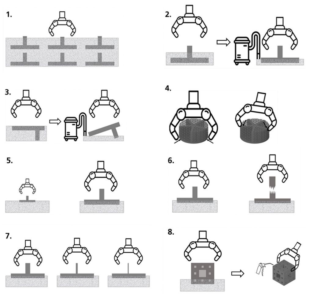
Previous solutions on the market face particular challenges when additively manufacturing more than one green part layer, as removing the surrounding supporting powder can result in collisions between parts. During powder removal, green parts must be partially exposed to allow gripping, and there is a risk of parts tilting. Some geometries can only be gripped at specific points due to their fragile structures. The gripper system must therefore accommodate both small and large green parts, including components with thin walls. The gripping force must be adjustable to handle parts with varying strengths. In addition, compressed air is required to remove powder from internal channels.

Two free-flowing stainless steel powders (316L and 17-4PH from IndoMIM) were selected for the project. Builds were carried out on an Innovent+ system using CleanFuse as the binder, followed by compression testing. Drying time and binder saturation were varied to adjust green part strength for subsequent automated depowdering tests. Using these parameters, bending strength was varied between 1-19 MPa, while compressive strength ranged from 3-38 MPa. Manual depowdering of the demonstrator parts confirmed that the selected geometries represent a broad spectrum of challenges, enabling comparison with the automated solution.
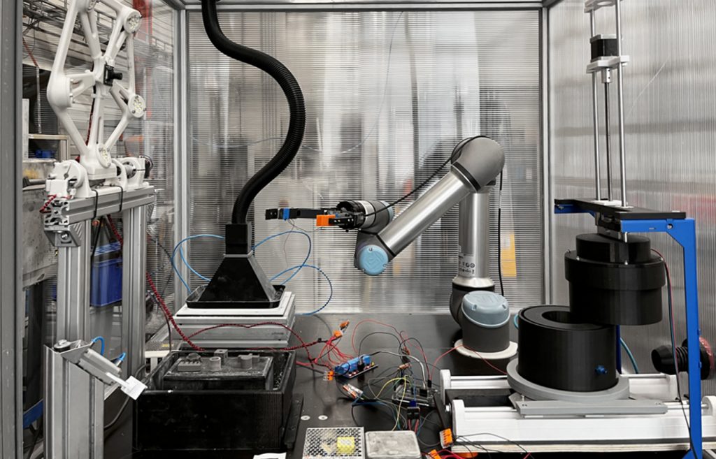
The project demonstrator consists of a work platform enclosed within a dustproof housing. A UR5e cobot equipped with a gripper, suction hood and compressed air chamber is installed on the platform, along with a job box transfer station and integrated extraction system (Fig. 3). After successful automated depowdering, the green parts are transferred to a transfer station.
Building on this setup, the automated depowdering process for the green parts is described below and consists of four main steps. First, primary depowdering occurs, removing the surrounding powder from the build job’s powder bed. The exposed green parts are then located using computer vision. Once the positions of the individual green parts are known, the robot can handle them. Handling may include a second, targeted post-depowdering step, but this is only necessary for certain green parts with inner channels. After the first or the second depowdering step, the green parts are automatically removed from the powder bed or post-depowdering station by the robot and made available for further handling, such as storage at a predefined location.
Key enabling technologies
Primary depowdering: extraction hood and part stabilisation
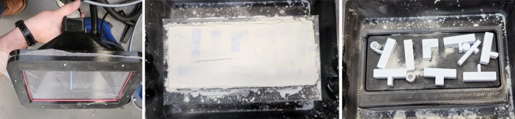
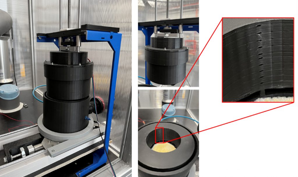
The prototype of the automated depowdering solution uses a suction hood with an integrated net (Fig. 4, left). First tests were carried out with corn starch to imitate the behaviour of typical Binder Jetting powders. This allows depowdering to be carried out over a large area and thus much faster than with conventional solutions that use a needle to extract/blow away the powder layer by layer. In addition, no shaking, ultrasound, or similar methods are used, which could damage the green parts due to vibration. The integrated net ensures that the green parts are easily fixed in place during suction, so they remain nearly in the same position and are not damaged by slipping or collisions. After depowdering with the suction hood, which removes most of the powder bed, a second, targeted depowdering step may follow, focusing mainly on the internal channels, using an extra compressed air chamber (Fig. 5). To move the green parts to the compressed air chamber using the cobot, they must first be identified using image recognition.
Part localisation and handling: vision, CAD templates, ArUco mapping
Each green part is illuminated from five different angles, and the resulting shadow images are combined into a single composite image. This creates a shadow that fully surrounds the green part, improving contrast and allowing multiple lighting directions to be superimposed to generate a closed contour that can be reliably identified through image processing. The composite image is then analysed with a computer vision-based approach using edge detection (Fig. 6).
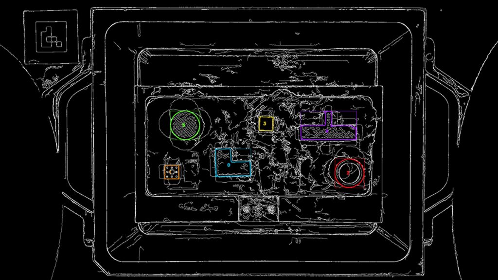
Contours are first identified in the combined image of the green parts and compared with reference templates rendered from the 3D-CAD data of the respective build job. Contours that match the rendered views are classified as green parts. Using the camera parameters and the known dimensions of each part, their position and orientation within the powder bed are determined. Once all identified green parts have been evaluated, their positions and orientations are communicated to the robot gripper system, enabling safe handling even if slight shifts occur during the depowdering process.
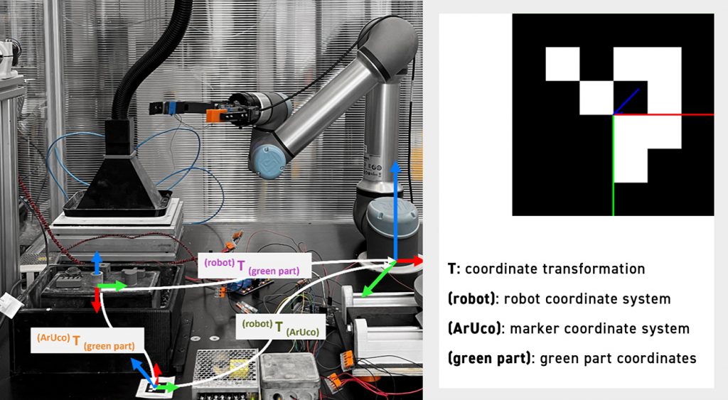
A small fiducial marker for computer vision, known as an ArUco marker (Fig. 7, top right), is captured in every image alongside the green parts, enabling the transfer of their coordinates into the robot’s coordinate system. Green part positions are first determined within the marker’s coordinate system using the camera parameters and known marker dimensions. Because both the marker and the robot are permanently installed, the transformation from the marker’s coordinate system to the robot’s coordinate system is fixed and known (Fig. 7, left).
Automated gripping point detection ensures that each green part is gripped at the most stable location to prevent damage. Based on the 3D CAD data for the identified parts, the system determines whether internal channels or similar features are present and whether subsequent fine depowdering in the compressed-air chamber is required. Parts needing this step are placed individually in the chamber, securely clamped, and rotated while compressed air is applied from all sides. Green parts that do not require fine depowdering bypass this stage and are transferred directly to the transfer station.
Gripper requirements and integration constraints
Because the gripper must handle both the suction hood and the green parts, a specialised gripper system – such as fin ray or kirigami grippers designed for sensitive components – was not used. Initial tests with Binder Jetting green parts indicated that the calculated minimum gripping force, based on part mass and weight, does not exceed the strength of the parts to be handled. Further detailed testing is still required. The Binder Jetting system operator must provide the automated system with information on green part strength and density, as well as the 3D-CAD data and build layout.
The prototype will be tested under real-world conditions and subjected to rigorous evaluation. The development of such solutions is essential to advancing Binder Jetting towards true production readiness. With its high build rate, Binder Jetting aims to bridge the gap between single-part production using other Additive Manufacturing processes and high-volume series production using conventional technologies. Automated powder removal is therefore necessary to ensure economic viability.
Outlook
In the end, the future of metal BJT does not depend solely on faster AM machines or improved materials, but on addressing the challenges that arise once the build is complete. Automated depowdering is not simply a matter of convenience; it is a decisive step towards making the technology truly industrial, scalable and economically viable.
By reducing manual labour, minimising health risks associated with powder exposure, improving consistency and accelerating production cycles, automation can help transform Binder Jetting from a promising innovation into a reliable manufacturing standard. If the industry is to unlock the full potential of this technology, investment in automated depowdering will be essential.
Authors
Lea Reineke
Project Manager
Fraunhofer IFAM
12 Wiener Strasse
28359 Bremen
Germany
www.ifam.fraunhofer.de/en
Florian Richter
Project Engineer
IPH Hannover
Hollerithallee 6
30419 Hannover
Germany
www.iph-hannover.de/en
www.iph-hannover.de/en/research/research-projects/?we_objectID=6717
Rolls-Royce hosts QualiJet project meeting
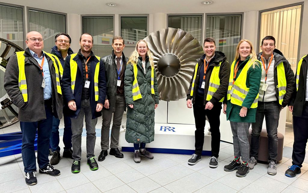
An IGF QualiJet project meeting was recently hosted at Rolls-Royce in Dahlewitz, Germany, bringing together project partners to review progress and further advance the development of automated depowdering solutions for Binder Jetting and other powder-based AM processes.
The meeting, hosted by Dr-Ing Enrico Daenicke, provided an opportunity for in-depth technical discussions and strategic alignment within the consortium. QualiJet aims to develop reliable and scalable automated depowdering systems that enhance process stability, quality assurance and industrial integration of powder-based Additive Manufacturing technologies.
Following the formal project sessions, participants were invited to tour Rolls-Royce’s jet engine production facilities in Dahlewitz. The visit offered valuable insight into the high-precision manufacturing environment in which advanced production technologies are implemented at scale. Meeting participants included Jack Schwarz, Oliver Hanitzsch, David Gerbert, Johannes Bergfeld and Daniel Kohl, as well as Lea Reineke (Fraunhofer IFAM), Florian Richter and Anne Vogler (IPH Hannover).
The meeting marked another important step forward in strengthening collaboration and progressing the industrialisation of automated depowdering solutions within powder-based AM.


