Prof Randall M German: Shaping the field of Powder Injection Moulding – a MIM2025 tribute
Held in Costa Mesa, California, the MIM2025 conference marked a significant moment for the Powder Injection Moulding community – not only for its technical programme and strong industry participation, but for a special symposium dedicated to honouring Prof Randall M German’s six-decade career. The tribute brought together former students, collaborators, and leading global experts to reflect on his scientific legacy and personal influence. Dr Animesh Bose reports from the event, highlighting Prof German’s unparalleled role in the rise of PIM. [First published in Powder Injection Moulding International volume 19 issue 2, Summer 2025 | 45 min read | View on Issuu | Download PDF]

Every year, the Metal Powder Industries Federation (MPIF) organises the International Conference on Injection Molding of Metals, Ceramics and Carbides. This year, the conference, referred to as MIM2025, was held from February 23-27 in Costa Mesa, California, USA. The conference featured a special group of presentations – each notated with a special icon in the programme – that had been inspired by Professor Randall M German (known to friends and colleagues as Rand), forming a symposium to honour and celebrate his exceptional six-decade career.
The organisers had issued personal invitations to many of Prof German’s former students and colleagues and these experts – coming from as far afield as Japan, Taiwan, India, and Spain – also shared some of their personal stories about their interactions with him. It was gratifying to see several of them accept the invitation to come and give a presentation.
All three co-organisers of this special segment of MIM2025 – Dr John Johnson, Prof Sundar Atre, and I – have shared a close association with Prof German spanning many decades. Dr Johnson and Prof Atre completed their PhDs under the guidance of Prof German, whilst my own association with Prof German began in 1985, when he invited me to join his group as a visiting scientist at the Materials Research Center at Rensselaer Polytechnic Institute (RPI) in Troy, New York, where he was then an Assistant Professor.
This collection of invited papers honouring Prof German’s legacy was delivered by global experts and reflected his extraordinary impact on the PM and PIM industries over a career spanning six decades.

MIM2025 in overview
Chris Chapman, Advanced Metalworking Practices LLC, and Bill Thorne from BASF co-chaired MIM2025. As in previous conferences, this year’s event touched on the advances in injection moulding of metals, ceramics and carbides; looked at the developments that contribute to the growth of Powder Injection Moulding; and, through the short presentations given by various companies on their products and developments, kept the MIM community apprised of their unique offerings.
This year’s tabletop exhibit featured approximately twenty exhibitors, with experts from leading MIM companies available at the booth to address any questions from interested attendees. Companies ranged from powders, production equipment, process technologies, testing, and quality control. The tabletop exhibit – always well attended and well received – serves as a valuable platform to engage with current and potential suppliers, receive assistance with production and materials enquiries, and discuss technical questions and the latest trends in real time.
The complete MIM2025 programme included a PIM tutorial presented by former MIMA President Matthew Bulger, the MIMA Standards Committee Meeting, the MIMA Board of Directors Meetings, the MIMA Membership Meeting, a welcome reception hosted by Arburg, technical sessions, process and product innovation discussions, as well as the aforementioned tabletop exhibition.
Low-pressure PIM and four decades of collaboration
The MPIF honoured me by inviting me to deliver the first presentation in this special track. Alongside my paper, ‘Low-Pressure Powder Injection Moulding (LP-PIM) of Metals and Ceramics’, I shared my history with Prof German.
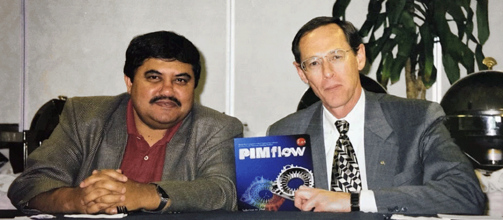
Our collaboration began in 1985, when he invited me to join his group at RPI as a visiting scientist. Fig. 2 shows one of our earliest photos together, alongside the then-new PIMFlow software. Judging by my full head of hair, I estimated the photo dates back to around 1986-87. Our collaboration continued even after I left RPI, culminating in two joint textbooks (Fig. 3).
![Fig. 3 The two books co-authored by Rand and Animesh, highlighting their ongoing collaboration: The Injection Molding of Metals and Ceramics, published by MPIF in 1997, and Binder and Polymer Assisted Powder Processing, published by ASM International in 2020 [1]](http://www.pim-international.com/wp-content/uploads/sites/2/2025/08/f03-1-1024x560.png)
Many carbide and ceramic components require complex shapes, traditionally fabricated by green machining or hard machining after consolidation. LP-PIM offers an alternative route for producing such complex parts. For example, Fig. 4 shows a 47 g hardmetal part with intricate internal features, produced via LP-PIM.
![Fig. 4 A tar-sand nozzle produced by MPI using the LP-PIM process [1]](http://www.pim-international.com/wp-content/uploads/sites/2/2025/08/f04-1.png)
I briefly outlined my journey from Rand’s lab at RPI to my current role consulting for the PM industry in both advanced processes and novel materials including PIM, sinter-based AM, refractory metals, hard materials, ultra-high temperature materials, metal and ceramic matrix composites. I described several applications for LP-PIM across ceramics and hardmetals, including cutting inserts, wire drawing dies, knives and blades for diverse industries, nozzles, drills, wear parts, sensor housings for space, and gun barrels.
![Fig. 5 A hardmetal twist-blade (top: as-moulded; middle: as-sintered; and bottom: sintered and machined) [1]](http://www.pim-international.com/wp-content/uploads/sites/2/2025/08/f05-1-1024x606.png)
LP-PIM is capable of fabricating both small and relatively large parts compared to conventional MIM. Fig. 5 illustrates a hardmetal LP-PIM twist blade nearly 20 cm long, used in nuclear steel cutting. The process has also produced blades over 30 cm for cutting diapers and silicon nitride gun barrels with internal twists of similar length. Additionally, LP-PIM can fabricate alumina parts, such as the textile industry spinneret shown in Fig. 6.
![Fig. 6 An alumina spinneret used in the textile industry (Courtesy William Corbett [1]](http://www.pim-international.com/wp-content/uploads/sites/2/2025/08/f06-1.png)
Advantages of low-pressure Powder Injection Moulding
Some of the key advantages of low-pressure Powder Injection Moulding (LP-PIM) over conventional PIM include the relatively low cost of tooling, which can be amortised over a much smaller number of parts, especially in the case of hard, wear-resistant components. In some instances, it has been possible to amortise tooling over as few as 100 parts per year, although a more typical figure is around 1,000.
LP-PIM also accommodates a wide range of part sizes, from very small components (less than 1 g) to parts exceeding 1 kg. Because the process operates at low pressure (around 100 psi), the tooling can be made from softer, more affordable materials such as aluminium or brass. The moulding temperature is also relatively low, typically around 100°C.
Furthermore, the same powder used in LP-PIM can often support a solid loading that is approximately 6–10% vol.% higher than in conventional PIM. This results in lower shrinkage of the final consolidated part, strengthening the case for LP-PIM in applications that benefit from its cost-effective tooling and enhanced material performance.
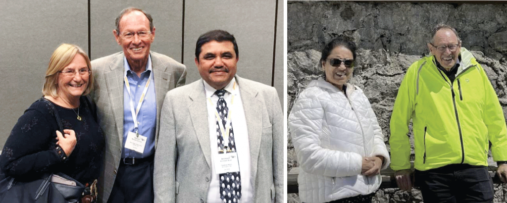
I concluded my presentation by noting that Prof German was not only a mentor to his students and fellow research collaborators but also interacted with them at a family level. As shown in Fig. 7, Prof German is pictured with his wife, Carol German, and me. Fig. 8 captures a moment with Prof German and Prarthana Bose, my wife. In Fig. 9, Prof German and I share a light moment together during a conference.

The shoulders of giants: synergising MIM and MEX
The next presentation in the series, ‘Synergising Metal Injection Molding and Materials Extrusion: Enhancing Manufacturing Flexibility and Performance,’ was delivered by Prof José M Torralba from the Department of Materials Science and Engineering at Universidad Carlos III de Madrid (UC3M), Spain. The presentation included several co-authors: Alberto Meza, Andrea Alonso, Angel Martín, Adrián Barbosa, Lucía García de la Cruz, Paula Alvaredo, and Monica Campos.

In his presentation, Prof Torralba outlined Prof German’s illustrious career and provided insights into their close interactions, including his receipt of an honorary doctorate from the UC3M. In addition, Prof German is a Fellow of the American Society for Metals, American Powder Metallurgy Institute, and American Ceramic Society. His awards include the Tesla Medal, Nanyang Professorship, Japan Institute for Materials Research Lectureship, Penn State Engineering Society Outstanding Research Award and Premiere Research Award, Distinguished Research Award from the Japan Society for Powder Metallurgy, University of California at Davis Distinguished Engineering Alumni Award, The Ohio State University Distinguished Engineering Alumnus Award, San Jose State University Award of Distinction, Technical Development Award from the Japan Institute of Metals, Honorary Member of Alpha Sigma Mu, Society of Automotive Engineers Teetor Award, Honorary Professorship at Northeast University of Technology, RPI Early Career Award, Geisler Young Metallurgist Award, Kuczynski Prize, and Samsonov Prize.

Prof Torralba adopted the theme of ‘on the shoulder of giants’, naming several of the stalwarts of the PM industry. The list of these names included Boettger, Wollaston, Acheson, Ostwald, Moissan, Coolidge, Frenkel, Lenel, Kuczynski, Kingeri, Coble, Johnson, Ashby, and, of course, German. Prof Torralba also spoke about Prof German’s 2004 investiture speech in which he focused on the importance of engineering education and the need to improve engineering studies at universities.
Combining high-entropy alloys and material extrusion
![Fig. 11 General steps for the AM processing of Metal HEA compositions [2]](http://www.pim-international.com/wp-content/uploads/sites/2/2025/08/f11-1024x525.png)
Prof Torralba proceeded with his technical presentation, which discussed a method for fabricating parts using lower-cost high entropy alloys (HEA) and a Material Extrusion-based AM process. Mixing existing PM alloys to achieve the HEA composition is an interesting approach that may provide a novel way of fabricating this class of material into useful complex shapes.
![Fig. 12 A comparison of the extrusion-based process Composite Extrusion Modelling (CEM), with Metal Injection Moulding and Additive Laser Manufacturing (ALM) [2]](http://www.pim-international.com/wp-content/uploads/sites/2/2025/08/f12-1024x322.png)
The overall processing steps are depicted in Fig. 11, while Fig. 12 illustrates a comparison of the extrusion-based process, referred to as Composite Extrusion Modelling (CEM), with Metal Injection Moulding and Additive Laser Manufacturing (ALM), also know as Laser Beam Powder Bed Fusion (PBF-LB).
![Fig. 13 HEA powder used for extrusion-based AM processing [2]](http://www.pim-international.com/wp-content/uploads/sites/2/2025/08/f13-1024x467.png)
Fig. 13 presents details of the characteristics of the HEA powder used in this investigation, including the composition and the X-ray analysis of the bcc powder. The feedstock was produced using paraffin wax (PW) and high-density polyethylene (HDPE) at a mixing temperature of 170ºC and a shear rate of 40 rpm. A schematic of the extrusion-based AM process employed is shown in Fig. 14.
![Fig. 14 Schematic diagram of the extrusion Additive Manufacturing machine [2]](http://www.pim-international.com/wp-content/uploads/sites/2/2025/08/f14-1024x535.png)
The presentation discussed the impact of processing parameters, with Fig. 15 highlighting how variations in layer thickness can result in voids within the build structure. The built parts were subjected to solvent debinding using Heptane at 60°C for 3 h, followed by thermal debinding. Sintering was carried out in high vacuum using a constant heating rate of 5°C/min to a sintering temperature of 1,360°C and held there for 2 h and cooled using a cooling rate of 5°C/min.
![Fig. 15 Shows the effect of layer thickness that can lead to build voids [2]](http://www.pim-international.com/wp-content/uploads/sites/2/2025/08/f15-1024x379.png)
Fig. 16 shows the SEM photomicrograph of the consolidated HEA material and the composition of two select areas within the microstructure, shown as Area 1 and Area 2.
![Fig. 16 Shows the microstructure and some analysis of the microstructure [2]](http://www.pim-international.com/wp-content/uploads/sites/2/2025/08/f16-1024x426.png)
Fig. 17 shows a higher magnification SEM photomicrograph where the composition of the matrix area is shown in Area 1 (shown in Fig. 16) and the composition of the Ni-Al rich precipitate is shown in Area 2 (shown in Fig. 16). The overall grain size is around 60 +/- 23 μm, and the precipitates are around 1.2 +/- 0.2 μm.
![Fig. 17 Shows a higher magnification SEM photomicrograph where the composition of the matrix area is shown as Area 1 (shown in Fig. 17) and the composition of the Ni-Al rich precipitate as shown in Area 2 (also shown in Fig. 16) [2]](http://www.pim-international.com/wp-content/uploads/sites/2/2025/08/f17-1024x565.png)
PIM of HEA feedstocks
This material was used to create feedstocks that were also processed by MIM. In this case, three powder loadings of 58, 60, and 62% v/v were used. The binder used was the same PW and HDPE that were mixed in the ratio of 1:1, as mentioned above. The parts were injection moulded at a temperature of 180°C, and a pressure of 6 bar to form small tensile test samples. The green parts were solvent debound and thermal debound, followed by final sintering that was carried out in a high vacuum of 10-5 Pa.
Two different peak temperatures and hold times were employed in the investigation (1,200°C for 6 h and 1,375°C for 3 h). A microstructural evaluation was conducted, and various mechanical properties of the material were assessed. The mechanical properties of the injection moulded HEA alloys are shown in Fig. 18. The tensile properties presented are not based on direct measurements of tensile properties but are, instead, extrapolated from a plastometer that uses hardness measurements to provide fairly accurate tensile properties.
![Fig. 18 Shows the density, hardness, and tensile properties (based on Plastometer testing) of a HEA alloy processed using MIM, as a function of powder loading in the feedstock [2]](http://www.pim-international.com/wp-content/uploads/sites/2/2025/08/f18-1024x631.png)
A personal tribute
On a personal note, Prof Torralba expressed deep admiration for Prof German, describing him as a trailblazer who has shaped his own career and inspired many others, including his students. Their close association with Prof German is reflected in Figs. 19 and 20 (below). Prof Torralba concluded his presentation with a simple slide reading, “Thanks a lot, Rand!” – a sentiment shared by many in the PM and PIM community.
![Fig. 19 Prof Torralba (centre), Prof German (left) and Carol (right) [2] & Fig. 20 Photograph taken at the 2006 PM Spanish Congress in Madrid, with Prof German (left) [2]](http://www.pim-international.com/wp-content/uploads/sites/2/2025/08/f19-and-20-1024x372.png)
Particle size and the earliest days of MIM
Matthew Bulger delivered the next paper in the series, titled ‘Particle Size Effects in MIM’. A former Master’s student under Prof German at RPI, Bulger is now a consultant and continues to share his expertise through the MPIF’s PIM tutorial, typically held at the start of the MIM conference.
Bulger began with a slide that read, “Welcome Back to the Fabulous 80s for MIM!” He outlined the early players in PIM, which, as he stated, was a brand-new way of making metal components. Among the key players mentioned was Parmatech Corporation, founded in 1973 and often referred to as MIM’s ‘ground zero’. The company played a pivotal role in the early dissemination of MIM, licensing it to numerous companies worldwide. One of Parmatech’s original co-founders, Ray Weich, left the company and ‘became the Pied Piper of MIM’.
Beyond Parmatech, several other early pioneers in MIM have also endured and continued to contribute to the industry’s growth. These include Brunswick (now FloMet – Cadence), Advanced Forming Technologies (ARC Colorado), Omark (now OptiMIM), 3M (Unitek), SSI (now DSB Technologies), Rocky Mountain Ortho, and Remington Arms.
Bulger noted that there was little academic support for PIM until 1986, when Prof German, along with two other professors at RPI, spearheaded a PIM consortium named Advanced Powder Processing (APP). With many early MIM companies working with ‘black box’ licensed technologies, twenty interested companies signed on to see basic R&D results. Prof German concentrated on powder characteristics that affected sintering, packing/solids loading, mixing, and shrinkage from moulded part to sintered parts and their final microstructure and properties.
The milestones that were outlined for the powders were that they pack well, sinter to high density, are compatible with the organic binder used, minimise cost, and show a consistent process response.

Powder sources and packing behaviour
Bulger pointed out that fine powder sources were limited in the 1980s, with elemental powders dominating. Carbonyl iron powder was the workhorse, though elemental nickel, molybdenum, tungsten, and copper powders were also available. For stainless steel production, ferrochrome powder was used in conjunction with available elemental powders to achieve the desired composition.
Pre-alloyed stainless steel powders came later, with gas atomised 316 available through Anval (now Sandvik) and water-atomised powder coming from Ametek. Ultrafine Powder (now part of Novamet) started its powder production around 1988, and Sandvik/Osprey began its operations in the early 1990s.
On the particle packing front, it was determined that size makes a difference in how powders pack, with larger powders packing more easily than smaller ones. The distribution of the powder also influences packing, as wide particle size distributions allow smaller powders to fit into the void spaces between larger particles, resulting in reduced distortion after sintering. The way Bulger put it: “The more parts shrink, the more they stink.” Monosize spheres with minimal interparticle friction are expected to have a packing of ~ 63%, while adding a small amount of powder that is around 10x smaller in size can lead to a packing of ~ 82%.
The 1988 APP study that Bulger spearheaded included the use of carbonyl Fe and gas-atomised Fe powders. The carbonyl Fe had an average particle size of 4.5 μm and a 4.3 g/cm3 tap density, while the gas-atomised Fe had an average particle size of 66 μm and a 5.0 g/cm3 tap density. The investigation looked at packing and sintering results at different small particle additions.
![Fig. 21 Results of green and sintered density using large and small iron powders [3]](http://www.pim-international.com/wp-content/uploads/sites/2/2025/08/f21-1024x478.png)
The results are graphically shown in Fig. 21. The results showed that the highest sintered density was obtained with 100% fine carbonyl powder. The highest packing was achieved using a 70% large and 30% small powder. The sintered density was found to be equal to packing density for the large monosize powders. Results showed that small powders tend to agglomerate and instead of being uniformly distributed and occupying spaces between the large particles, they agglomerate, resulting in large porosity and cracks as depicted in Fig. 22.
![Fig. 22 Schematic showing the agglomeration of small particles in a mix of large and small iron powders resulting in large pores and cracks [3]](http://www.pim-international.com/wp-content/uploads/sites/2/2025/08/f22-1024x443.png)
Another result outlined showed that a wide powder particle size distribution benefited the powder packing (shown in Table 1). Another conclusion from this investigation was that fine ‘monosize’ particle size (carbonyl Fe) feedstock is harder to mould than feedstock made with a wide particle size distribution of a gas atomised powder (17-4PH) for similar solids loading. The work also demonstrated that fine particle sizes reduce distortion during sintering, with the distortion measured by the deflection of unsupported tensile bars, all at the same solids loading.
![Table 1 Shows increased packing when using a wider powder particle size distribution [3]](http://www.pim-international.com/wp-content/uploads/sites/2/2025/08/t01-1024x206.png)
Bulger concluded his presentation by asserting that the fundamentals of particle size and particle size distribution significantly influence the reliability of MIM as a production process. The work and publications of Prof German on these issues spanned five decades and established the foundational scientific principles for process basics that are now often taken for granted.
Trends in R&D
The next presentation came from Dr Gemma Herranz, from Universidad de Castilla-La Mancha (DYPAM) and CEO of Blesol Tech, Ciudad Real, Spain. She combined her personal journey, in which Prof German played a significant role, with a technical presentation discussing trends in R&D and exploring synergies between PIM and AM.
Her journey in the PIM sector is something of a testament to Prof Germans’ global influence, with Dr Herranz receiving the first PIM-focused PhD in Spain, developed within a project led by Prof Torralba. This has led to another groundbreaking role in Spain, with Blesol Tech the first Spanish company producing injectable and buildable feedstocks and offering specialised services for sectors such as energy, automotive, and aerospace.
The synergy between PIM and AM outlined by Dr Herranz can allow the expansion into new markets and progressive scaling of applications. Fig. 23 shows some of the R&D areas that are of interest, with Fig. 24 showing some of the broad focus areas of R&D from DYPAM. The energy sector R&D was focused on the development of solid oxide fuel or electrolysis cells (SOFC and SOEC, respectively), paying attention to durability, cost, and scalability. The two main areas of interest were interconnects and anodes.
![Figs. 23 & 24: Fig. 23 (Left) Trends in R&D [4]; Fig. 24 (Right) Current advances from DYPAM [4]](http://www.pim-international.com/wp-content/uploads/sites/2/2025/08/f23-and-24-1024x471.png)
For interconnects, the feedstock and filaments were not commercially available. Feedstocks and filaments were developed, and critical design improvements were made to maximise PIM capabilities. In the case of the anodes, the R&D focused on the development of two ceramic feedstocks and the tailoring of porosity to maximise performance.
The typical pathway involves prototyping using the AM process and developing mass production at a reduced cost. These developments, which include electrochemical performance testing and component design, are conducted in close collaboration with the National Hydrogen Centre (CNH2) in Spain, where the electrochemical characterisation of the produced materials takes place. Fig. 25 shows some of the test results from the electrochemical characterisation.
![Fig. 25 Test results of electrochemical characterisation [4] (Source: DOI: 10.1016/j.ijhydene.2021.02.097)](http://www.pim-international.com/wp-content/uploads/sites/2/2025/08/f25-1024x484.png)
In aerospace, tailoring the composition and control of the Ceramic Injection Moulding parameters enables the regulation of the existing phases, thus influencing the dielectric and thermal properties of the ceramics. Research into materials explores the potential of incorporating graphene into cordierite composites using CIM, contributing to the development of advanced materials for aerospace applications.
CIM samples demonstrate a greater mullite phase content, a more homogeneous microstructure, and reduced porosity. This work is being conducted in collaboration with INTA (the Spanish National Institute for Aerospace Technology) as part of a dedicated research project. Fig. 26 shows a lens holder as an example of the applications developed in the aerospace sector using graphene-reinforced cordierite.
![Fig. 26 This aerospace lens holder is one application for graphene-reinforced cordierite [4]](http://www.pim-international.com/wp-content/uploads/sites/2/2025/08/f26-1024x548.png)
Some of the most promising areas of development in aerospace include the efforts focused on modelling, processing, and validating metal alloys with 2D reinforcements, achieving significant modifications in mechanical and functional properties. The modelling encompasses meta-, micro-, and meso-scale structures, while processing involves designing experiments for Fused Filament Fabrication (FFF) and other Additive Manufacturing technologies. These developments target applications demanding unusual combinations of properties, achievable through the design of metamaterials with tailored architectures. These developments create opportunities for tailoring materials to meet the demanding combinations of properties required in aerospace, automotive, and energy applications.
Biomaterials and functional materials development
Another significant focus of Dr Herranz’s lab is biomaterials and their processing. One material in development is a nano-sized 3-YSZ (Yttria Stabilised Zirconia) powder, intended for producing YSZ scaffolds for bone tissue engineering via FFF.
The steps for biomaterial development included designing the filament formulation, mechanically evaluating the filaments, characterising the built parts, and assessing mechanical properties and the tendency for infections (illustrated in Fig. 27). In the future, biomaterial development will incorporate 2D materials to enhance bioactivity, as well as in vitro and in vivo testing.
![Fig. 27 The steps used for biomaterial development [4] (Source: DOI:10.1016/j.jmrt.2024.02.057)](http://www.pim-international.com/wp-content/uploads/sites/2/2025/08/f27-1024x603.png)
The other areas of focus included rheology studies for filament development and the creation of functional materials. Here, significant results have been achieved, such as a notable enhancement of the luminescent properties of the developed materials (Fig. 28), which demonstrates the ability to fine-tune these properties by carefully controlling the processing parameters. This opens up new possibilities for tailoring functional responses through advanced manufacturing routes.
![Fig. 28 Application areas of functional materials [4] (Source: DOI: 10.1016/j.ceramint.2019.12.190)](http://www.pim-international.com/wp-content/uploads/sites/2/2025/08/f28-1024x337.png)
Collaborations and future directions
During the presentation, Dr Herranz also highlighted important collaborations that have enabled specialisation in diverse sectors, including the National Hydrogen Center (CNH2), Ciudad Real Hospital, and the National Institute of Aeronautical Technologies (INTA), among others. She also discussed Blesol Tech, which took her on the journey from research to industry. According to Dr Herranz, PIM technology shows enormous potential across various sectors, and her work is pushing the boundaries of innovation through advanced materials and customised solutions.
She concluded by stating that we are celebrating Prof German’s legacy, whose inspiring work continues to guide and transform our journey. Fig. 29 shows Dr Herranz with Prof German, while Fig. 30 also features Prof Torralba and illustrates his close connections with the Spanish PM community.
![Figs. 29 & 30: Fig. 29 (Left) Prof German with Prof Herranz, pictured in earlier years [4]; and Fig. 30 (Right) Prof Herranz (second from left) and Prof German (centre) among peers at MIM2025 [4]](https://www.pim-international.com/wp-content/uploads/sites/2/2025/08/f29-and-30-edited.png)
Compensating for shrinkage when sintering BJT parts
The next presentation in the series was delivered by Dr Pavan Suri from HP, in collaboration with his co-authors Ravi Mayavaram and Narendra Singh from Altair. Their work, titled ’Automatic Shape Compensation for Shrinkage During Binder Jet Sintering Process,’ was jointly presented by Drs Suri and Singh.
Dr Suri, who completed his PhD under the guidance of Prof German, introduced the motivation behind the study, highlighting the growing significance of Binder Jetting as a key Additive Manufacturing process. This method avoids melting, reduces energy consumption, and enables the production of large, complex-shaped components. For BJT to be effective, accurate shrinkage prediction and compensation are essential.
Singh, Programme Manager for Manufacturing Solvers at Altair, elaborated on the computational theory and simulation methodologies underpinning the work. Fig. 31 shows the general steps associated with BJT.
![Fig. 31 General steps associated with the Binder Jetting process [5]](http://www.pim-international.com/wp-content/uploads/sites/2/2025/08/f31-1024x401.png)
For sintering analysis, the input data included initial geometry of green powder compact, initial average particle size, initial density field, sintering constitutive law and its parameters, grain growth law and its parameters, sintering temperature curve, friction and support conditions. The Simulation Output provides a timeline of the following: part shape and dimensions, density, stress field, strain field, grain size, and strength properties.
![Fig. 32 Several parts used for validation [5]](http://www.pim-international.com/wp-content/uploads/sites/2/2025/08/f32-1024x526.png)
Several parts (Fig. 32) were chosen for validation examples. The simulation carried out on 316L requires several material characteristic inputs, such as the thermomechanical and viscosity data shown in Table 2.
![Table 2 Thermomechanical data and viscosity data for 316L used in the simulation [5] Some fields are left blank where input data was either not available or not required by the simulation model](http://www.pim-international.com/wp-content/uploads/sites/2/2025/08/t02-1024x455.png)
The sintered prediction analysis of the part designated as the bracket is shown in Fig. 33, and an actual sintered versus a simulated bracket is shown in Fig. 34.
![Fig. 33 The sintered prediction analysis of the part designated as the bracket [5]](http://www.pim-international.com/wp-content/uploads/sites/2/2025/08/f33-1024x528.png)
![Fig. 34 Shows a comparison between an actual sintered part with a simulated part [5]](http://www.pim-international.com/wp-content/uploads/sites/2/2025/08/f34-1024x309.png)
These simulations are used for hot spot analysis to evaluate part survivability during debinding, enhance design robustness, and detect, avoid, and compensate for deformation during sintering. Use of tools such as Physics AI further enables rapid design iterations to check for green part robustness prior to the build. For repeatability studies, as not all parts are the same, there is variation due to the processes, material and limitations due to the model assumption and process repeatability. Bridging the gap between simulations, compensation, and actionable outcomes is an ongoing focus.
Sintering studies inspired Prof German
TS (‘Shiv’) Shivashankar gave the following presentation in this series from Indo-MIM, entitled ‘Sintering Studies Inspired by RMG.’ The paper had two co-authors: Ramana Reddy and Sridhar Dharshan. Dr Shivashankar did his PhD with Prof German as his supervisor (Fig. 35), before eventually settling back in India, where he is now VP at Indo-MIM, one of the largest MIM companies.
![Fig. 35 An earlier photo of students with Prof German [6]](http://www.pim-international.com/wp-content/uploads/sites/2/2025/08/f35-1024x353.png)
He gave a fascinating presentation and introduced the concept of the ‘centre of sintering.’ The inspiration came from Prof German’s lab and Dr Shivashankar pointed out that sintering simulations in the past have been more on the particulate rather than the component level. Particle size, shape, PSD, and solids fraction are all fixed, and it’s the components that change. Models that can predict distortions and suggest alternate ‘setting methods’ are going to be highly beneficial.
![Fig. 36 A schematic of the forces exerted on green parts during sintering (FBD) [6]](http://www.pim-international.com/wp-content/uploads/sites/2/2025/08/f36-1024x486.png)
Fig. 36 shows a schematic of the forces exerted on green parts during sintering (FBD). It is interesting to note that gravity can aid and oppose sintering at the same time; Fig. 37 shows the schematic of the sintering pull force toward the centre of gravity. An important conclusion from this approach is that it is not the magnitude of the friction force, but the position on the part where it influences that determines the distortion from the nominal.
![Fig. 37 A schematic of the sintering pull force toward centre of gravity [6]](http://www.pim-international.com/wp-content/uploads/sites/2/2025/08/f37-1024x533.png)
The centre of sintering experiments were run by the use of tensile bars with equal external weights on the two ends, a bar with no weights, and a bar with the external weight placed only on one side (that shifts the centre of gravity toward the side where the external weight was placed). Schematically, Shivashankar illustrated the difference between the centre of sintering (CS) shown in Fig. 38 and the centre of gravity (CG) in Fig. 39.
![Fig. 38 A schematic of the concept of centre of sintering [6]](http://www.pim-international.com/wp-content/uploads/sites/2/2025/08/f38-1024x509.png)
![Fig. 39 A schematic showing the difference between centre of sintering and centre of gravity [6]](http://www.pim-international.com/wp-content/uploads/sites/2/2025/08/f39-1024x581.png)
He went on to state that the double weight experiments suggested here could assist in developing stress-strain curves for each material. The concept of the centre of sintering was introduced as a pivot point for sintering, and manipulating the CS to a plane that is wider or thicker will help achieve consistent first-pass yields.
Finally, Dr Shivashankar promoted the use of simulation software to analyse various ceramic ‘setting or staging’ options. According to him, manipulating the inter-particle spacing is key to improving the strength of green parts during sintering. This parameter combines the effect of mean particle size, size distribution, and powder volume fraction.
Thermal management materials and applications
The next paper in the invited talk series was presented by Dr John L Johnson, COO of Novamet / Ultrafine Powders, who completed his PhD under the supervision of Prof German. His presentation was entitled ‘Powder Injection Moulding of Thermal Management Materials,’ began with an overview of key application areas. These included semiconductor chips (10–100 W/cm²), high-brightness LEDs (10–100 W/cm²), lithium-ion batteries under high discharge conditions (5–100 W/cm²), phased array antennas (1–50 W/cm²), RF power devices (500–800 W/cm²), and plasma-facing components in fusion reactors (700–2,000 W/cm²).
He also discussed current thermal management solutions, which fall into three broad categories: air cooling, liquid cooling, and immersion. Air cooling typically involves the use of heat sinks and fans. Liquid cooling can be implemented in several ways, each offering varying levels of heat dissipation: direct-to-chip microchannels (up to 790 W/cm²), sprays (up to 1,200 W/cm²), jet impingement (up to 2,000 W/cm²), and heat pipes (ranging from 10,000 to 20,000 W/m²). Dr Johnson also pointed out that the thermal performance of the current heat sinks is not optimised.
MIM enables the production of complex designs that enhance thermal performance.Copper heat sinks produced via MIM, using –25 μm powders with a solids loading of 52–68 vol.% and sintered in hydrogen at 1,000–1,075°C, can achieve final densities of 93–94% of theoretical, with shrinkage ranging from 9–19%, depending on the initial loading and final density. However, Dr Johnson noted that improper processing conditions can lead to oxide reduction, which may result in part swelling.
![Fig. 40 A MIM copper heat sink [7]](http://www.pim-international.com/wp-content/uploads/sites/2/2025/08/f40-1024x407.png)
Fig. 40 shows a MIM copper heat sink; Fig. 41 shows two cross-sectional microstructures of copper when sintered using a high heating rate and a slow heating rate. The microstructure of the part produced using a high heating rate was quite porous, with large pockets, compared to the microstructure of the part that was heated slowly to the sintering temperature. The high porosity of the parts sintered at high heating rates is due to the entrapment of the gases evolving during the heating-up phase. Dr Johnson also pointed out the negative effect of iron impurities in copper-based material on the thermal conductivity.
![Fig. 41 Microstructures of copper parts heated to the sintering temperature using a fast heating rate (left) and a slow heating rate (right) [7]](http://www.pim-international.com/wp-content/uploads/sites/2/2025/08/f41-1024x429.png)
Dr Johnson went on to present the fascinating concept of two-material injection moulding of a 13 μm Cu powder and a -150/+325 mesh Cu powder that were co-sintered at 1,050°C. Fig. 42 shows a two-material injection moulded copper part (left), with the section produced using coarse powders reaching a sintered density of 64% and an average porosity of 22 μm. The middle image displays the microstructure of both regions of the part, made from coarse and fine powders. The right-hand image presents an SEM photomicrograph of the coarse powder region, showing the porosity and neck formation between the copper particles.
![Fig. 42 Two-material injection moulded copper part (left) with sintered density of 64% in the coarse powder section and average porosity of 22 μm. The middle image shows the interface between areas formed with coarse and fine copper powders, while the right image is an SEM photomicrograph of the coarse powder region [7]](http://www.pim-international.com/wp-content/uploads/sites/2/2025/08/f42-1024x445.png)
Additive Manufacturing and alternative heat spreaders
His presentation also briefly covered the area of additively manufactured copper thermal management parts. He showed examples of copper heat sinks based on Material Extrusion and BJT. Both processes were based on using polymer-assisted AM followed by removal of the binder and sintering, with the MEX process having a closer resemblance to the MIM process. Fig. 43 shows pictures of heat sinks that have been fabricated from copper using the MEX process and 3DEO’s variant of the Binder Jetting processes.
![Fig. 43 Heat sinks fabricated from copper using MEX, alongside a pure copper heat sink produced by 3DEO’s sinter-based Additive Manufacturing technology [7]](http://www.pim-international.com/wp-content/uploads/sites/2/2025/08/f43-1024x472.png)
Dr Johnson also covered W-Cu-based heat spreaders fabricated with tungsten content between 80 and 90 wt.% and using sub-micron W-Cu powder, a solid loading of 52 vol.%, and liquid phase sintering at ~1,300°C in a pure hydrogen atmosphere.
![Fig. 44 Several heat spreaders made from W-Cu [7]](http://www.pim-international.com/wp-content/uploads/sites/2/2025/08/f44-1024x200.png)
Fig. 44 shows the pictures of several heat spreaders made from W-Cu; the presentation also showed some examples of heat sinks made from Mo-Cu composites. Dr Johnson also covered some ceramic-based heat spreaders made from AlN with 2-6 wt.% Y₂O₃ made by PIM. The powder used was for 1.5 μm, using a solids loading of 60 vol.%. The material was liquid phase sintered at 1,850°C using a nitrogen atmosphere, where the Y₂O₃ forms an eutectic liquid with Y₂O₃. Fig. 45 shows PIM heat spreaders made from AlN–Y₂O₃.
![Fig. 45 PIM heat spreaders made from AlN – Y2O3 [7]](http://www.pim-international.com/wp-content/uploads/sites/2/2025/08/f45-1024x410.png)
In summary, Dr Johnson stated that thermal management remains an ongoing challenge. However, MIM and metal AM can provide new design solutions from many high thermal conductivity materials used as heat sinks, heat pipes, and heat spreaders. The materials discussed were Cu, Al, W-Cu, Mo-Cu, and AlN-Y₂O₃. Some of the key factors in making desirable high thermal conductivity parts include the effects of impurities, microstructures, and cost.
Ti alloy compact development
The next speaker, Prof Emeritus Hideshi Miura of Kyushu University, travelled all the way from Japan to attend this conference and participate in the celebration of Prof German’s career. He previously worked with Prof German in his lab in the USA.
In ‘Development of Innovative Ti Alloy Compacts Through MIM Process,’ Prof Miura focused on the effect of microstructural refinement on the mechanical properties of injection moulded Ti-6Al-4V alloys. His study concentrated on the impact of using fine powder, the effect of α+β region sintering, and the effect of hydrogenation and dehydrogenation treatment. He also discussed the influence of pore size and grain size on the high-cycle fatigue strength.
Titanium alloys have excellent property combinations, including high specific strength, good corrosion and thermal resistance, and excellent biocompatibility. These attributes make Ti alloys especially suitable for applications in the aerospace, automotive and medical sectors.
Among the Ti-alloys, Ti-6Al-4V has a good balance of strength, ductility, and toughness, but has poor workability and high forming cost. It is expected that MIM will be a suitable technique for fabricating more complex-shaped parts with mass production capability (this by reducing the forming cost).
In his earlier studies, Prof Miura determined that the tensile properties of MIM Ti-6Al-4V alloy compacts are dictated primarily by relative density and oxygen content after sintering rather than the raw material powders and process conditions. The tensile strength (880 MPa) increases significantly with increasing density and oxygen content up to 0.5 mass%. The equation that connects the strength with the oxygen content is given below:
σ [MPa]=700*Oxygen [mass%] + 10ρ [%] – 315 [Oxygen < 0.5% and density > 94.5%].
Prof Miura also observed that ductility is excellent with oxygen content of less than 0.35 mass% (>10%). In this investigation, the MIM process was applied to strengthen Ti-6Al-4V alloy compacts through the addition of fine Fe, Cr, and Mo powders. The effects of third additive elements and sintering conditions on the mechanical properties and microstructures of the injection moulded compacts were primarily investigated. The Fe, Cr, and Mo are β-phase stabilising elements that strengthen the alloy. A term designated as Mo equivalent, based on the mass percentage of several elemental additives, was determined, and the equation is shown below:
[Mo]eq = [Mo] + [Ta]/5 + [Nb]/3.6 + [W]/2.5 + [V]/1.5 + 1.25[Cr] + 1.25[Ni] + 1.7[Mn] + 1.7[Co] + 2.5[Fe]
One of the compositions he investigated was Ti-6Al-4V-4Mo, which, based on the equation above, had a [Mo]eq of 6.7 and sufficient ductility of over 10%. The additions of Fe or Cr were based on the [Mo]eq, which provides a phase-stability classification. When injection moulding these alloys, the relative density was relatively high, exceeding 97% due to the enhancements of elemental diffusion and densification by additional fine particles of Al-40V, Mo, Fe and Cr powders. The strengthening of Ti-6Al-4V alloy compacts with added Mo, Fe, or Cr powder was attributed not only to fine microstructural modification but also to solid solution strengthening due to the increased β phase content.
![Table 3 Tensile properties, density, and sintering conditions [8]](http://www.pim-international.com/wp-content/uploads/sites/2/2025/07/t03-1024x192.png)
Table 3 shows the properties of the modified Ti-6Al-4Al alloys with the additions of Mo, Fe, or Cr. All three new alloys show an increase in strength while the elongation remains almost the same. One problem with injection-moulded Ti-6Al-4V alloy compacts is their low fatigue strength, as shown in Table 4.
![Table 4 Comparison of wrought and MIM Ti-6Al-4V alloy [8]](http://www.pim-international.com/wp-content/uploads/sites/2/2025/08/t04-1024x193.png)
The problem has its roots in the difference in the microstructures between the wrought and MIM samples. The wrought microstructure is much finer than the MIM Ti-6Al-4V microstructure (Fig. 46). One method being tried is the use of TiB2.
![Fig. 46 Wrought microstructure (left) shows a fine equiaxed α+β structure obtained by forging & heat treatment. MIM microstructure (right) shows coarse α+β lamellar and large prior β grains [8]](http://www.pim-international.com/wp-content/uploads/sites/2/2025/08/f46-1024x323.png)
At high temperatures – and thus during sintering – TiB2 particles change to many TiB particles and work as pinning particles against the grain growth of the prior β phase. Fig. 47 shows the EBSD (electron backscatter diffraction) microstructure showing grain refinement with increasing boron content.
![Fig. 47 EBSD of Ti-based alloy with increasing boron content. The grain refinement with increasing B content is quite evident [8]](http://www.pim-international.com/wp-content/uploads/sites/2/2025/08/f47-1024x263.png)
Fatigue testing was carried out on several Ti-based alloys, beginning with a baseline Ti-6Al-4V alloy in both sintered and HIPed conditions. Modified versions incorporating 0.4B were tested with and without HIP, showing improved fatigue performance. The standard fatigue strength for wrought Ti-6Al-4V was 510 MPa; this served as a benchmark. Building on this, Prof Miura further investigated a dual-modified alloy incorporating 4Mo and 0.4B. These samples were sintered for 4 or 8 h, with some also HIPed. The fatigue properties of the baseline, 0.4B-only, and 4Mo-0.4B alloys – in both HIPed and non-HIPed conditions – were compared, with results shown in Fig. 48.
![Fig. 48 Fatigue strength of Ti-6Al-4V alloy and its modification using 0.4B and 4Mo-0.4B processed by both sintering and Hot Isostatic Pressing (HIP) [8]](http://www.pim-international.com/wp-content/uploads/sites/2/2025/08/f48-1024x516.png)
Prof Miura also discussed an alternative method for refining microstructure through hydrogenation and dehydrogenisation (HDH), as well as another sintering technique at lower temperatures, specifically at 980°C (which is just below the β transus of 1,000°C) for periods of 24, 48, and 96 h. Fig. 49 illustrates the fatigue strength of several Ti-6Al-4V alloys and their variations, including those of HDH and HDH-HIP parts. The figure also presents the properties of a typical MIM Ti-6Al-4V alloy alongside those of standard wrought material. Prof Miura concluded his presentation with several key findings regarding the mechanical properties and microstructural optimisation of MIM Ti-6Al-4V alloys through elemental additions and processing strategies.
![Fig. 49 Fatigue strength of Ti-6Al-4V alloy and its modification using 0.4B and 4Mo-0.4B processed by both sintering and hot isostatic pressing (HIP) [8]](http://www.pim-international.com/wp-content/uploads/sites/2/2025/08/f49-1024x493.png)
The study found that the addition of both molybdenum (Mo) and boron (B) led to a refined microstructure, with fine prior-β grains and a fine lamellar structure. Mo contributed to improved static properties, while B enhanced dynamic performance. Specifically, compacts of Ti-6Al-4V with 4 wt.% Mo and 0.4 wt.% B demonstrated excellent tensile properties, achieving a strength of 1,030 MPa and 13% elongation.
The fatigue strength of these 4Mo-0.4B modified compacts was reported as 430 MPa in the as-sintered condition (8 h) and 470 MPa following HIP treatment. These values were comparable to compacts containing only 0.4 wt.% B.
Tensile strength in MIM Ti-6Al-4V compacts was found to correlate with an experimental equation that incorporates oxygen content (O), density (ρ), and grain size (D), demonstrating the complex interplay of these factors in determining mechanical performance.
Notably, excellent static and dynamic mechanical properties were achieved through a combination of techniques aimed at refining the microstructure. These included the addition of third and fourth alloying elements, the use of fine powders, sintering within the α + β phase region, and the application of hydrogenation–dehydrogenation treatment.
A detailed analysis of fatigue behaviour revealed the critical role of pore-to-grain size ratios. When the maximum pore diameter exceeded twice the grain diameter, fatigue fractures initiated from the largest pore in the sintered compacts, with a dramatic decline in fatigue strength observed. Conversely, when the pore-to-grain size ratio was below two, fracture initiation shifted to facets within the grains.
Finally, the research emphasised that fatigue strength increases with higher relative density and that the relative size of pores to grain size is a decisive factor in achieving high fatigue performance in all sintered materials.
Microstructural evolution of WC/Co alloys with vanadium carbide additions
The next presentation in the series was given by Dr Joseph (‘Joe’) Tunick Strauss from HJE Company, Inc. Strauss also did his PhD under the guidance of Prof German and was one of his early graduate students who completed his PhD thesis in 1991 from Rensselaer Polytechnic Institute.
On a personal note, Joe was one of the three people responsible for my continued stay in the USA. He helped me get my first automobile in the USA (without which living in the US for a long time is extremely difficult) and was an excellent guide who introduced me to US culture. He had an exceptionally interesting story about how he migrated to MIM, though it had very little to do with his PhD topic.
His presentation was entitled ‘Microstructural Evolution of WC/Co Alloys with Vanadium Carbide Additions’, though he did mention in his presentation that I had first told him that he could present some of his thesis work. I did, however, encourage him to include a connection to Metal Injection Moulding; he faced the unenviable task of not only presenting his research but also weaving in the story of how he became involved in MIM.
Essentially, in Strauss’ words, after several tedious years attempting to find a mechanism for why VC additions lead to grain refinement in WC-Co-based hardmetals, and failing to identify any existing model that fit, he was compelled to develop his own model to accommodate the microstructural data. Having personally worked in hardmetals, I can somewhat appreciate the tedious nature of the project. Even amidst his struggles to align his results with existing theories, Strauss, in his characteristic manner, managed to find some humour.
Dr Fritz Lenel (1907–2003), a giant in the Powder Metallurgy field, once told Strauss, “I have been working with these LS&W (Lenel, Smith & Wulff) theories for thirty years and they just do not work.” Similarly, M. Barsoum, in his book Fundamentals of Ceramics (McGraw-Hill), observed that “all sintering data can be made to fit all sintering models.” These remarks reflect the longstanding challenges and debates surrounding the theoretical modelling of sintering – a reminder that practical understanding often outpaces the predictive power of existing models.
Strauss had already completed his PhD in carbides, but by that time, he had been captivated by the allure of Powder Injection Moulding. In 1986, Prof German and two other professors established the first PIM consortium at RPI. This consortium was named Advanced Powder Processing (APP), where several students and postdocs (including yours truly) had their first exposure to MIM. Strauss, who was almost a wizard when it came to equipment, got pulled entirely into this emerging field.
He established his own company, which he named HJE (which is still in operation today). When Strauss first formed his company, he intended to sell small custom atomisers and, to increase sales, developed MIM for precious metals. As precious metal powders could be processed efficiently using the HJE atomisers, it was hoped that jewellery companies would utilise MIM and require an atomiser. Many HJE atomisers have been sold to produce precious metal powders for MIM and are now also being used for AM-grade powder.
![Fig. 50 The first advertisement by HJE, a company founded by Joe Strauss [9]](http://www.pim-international.com/wp-content/uploads/sites/2/2025/08/f50-1024x696.png)
His early advertising stated that HJE offered fully integrated mini-MIM services, including prototype mould manufacturing and in-house gas and water atomisation for special alloys. The small atomisers subsequently became a significant part of his business, as illustrated in the advertisement by HJE shown in Fig. 50.
![Fig. 51 Some of the early jewellery parts made by HJE [9]](http://www.pim-international.com/wp-content/uploads/sites/2/2025/08/f51-1024x382.png)
Before long, Strauss was producing some fascinating and innovative PIM parts, especially helping folks in the jewellery area. Some of the parts made by HJE are illustrated in Fig. 51. Shortly thereafter, Strauss began to experiment with some novel ideas, such as developing concepts for hollow jewellery parts (Fig. 52).
![Fig. 52 A couple of concepts for making hollow jewellery parts made by HJE [9]](http://www.pim-international.com/wp-content/uploads/sites/2/2025/08/f52-1024x398.png)
He explored two different strategies for hollow jewellery (as shown in Fig. 52): (1) building soluble cores on which he over-moulded the actual PIM part and subsequently washed out the cores and (2) the concept of sinter-bonded MIM. The use of platinum group alloys has also been explored, and Fig. 53 shows a 50Pt–50Rh watch case and its manufacturing process.
![Fig. 53 Shows a MIM mould (left), the green bodies after injection (centre) and the finished 50Pt-50Rh watch case after sintering (right) (Courtesy C.HAFNER GmbH + Co. KG; from Laag, T. & Heinrich, J., Advantages and Challenges of Platinum Group Metals Powder Processing, SFS 2018) [10]](http://www.pim-international.com/wp-content/uploads/sites/2/2025/08/f53-1024x398.png)
Strauss concluded the presentation by stating that MIM research was more enjoyable and rewarding than carbide research. He leveraged his MIM experience to introduce the technology into fresh areas, such as precious metals for dental use, jewellery, and watches, as well as new materials. He noted that MIM is gradually gaining traction in jewellery and watches. He has also applied his precious metal MIM experience to sinter-based AM.
The HPM process: MIM powders combined with pressing and sintering
The presentation ‘Press-and-Sinter Parts Using MIM Powders’ was by one of Prof German’s early PhD graduate students, Prof Kuen-Shyang Hwang (also known as KS) from HPM Labs, alongside co-author Yang-Liang Fan from United Powder Technologies. Prof Hwang travelled all the way from Taiwan to attend the celebration of Prof German’s career.
This was an intriguing presentation in which the researchers used MIM powders to achieve high-performance, high-density press and sintered (HPM) parts. Prof Hwang pointed out that as the sintered density increases, so do all the mechanical properties. Fig. 54 shows a schematic of the changes in mechanical properties with density. Here, there are three distinct zones (1, 2, and 3), represented as follows: Zone 1, Conventional PM; Zone 2, Warm Compaction + High Temp, Sintering; Zone 3, HPM and MIM.
![Fig. 54 Variation of mechanical properties with density (Source: Höganäs Handbook 3, 2013) [10]](http://www.pim-international.com/wp-content/uploads/sites/2/2025/08/f54-1024x590.png)
Prof Hwang faced the question of how to improve the density and properties. There are really three ways to achieve this: high compressibility powders, warm compaction, warm die compaction, and high-temperature sintering. As the sintered density increases, the next question that arises is how the pore size and shape affect the properties, though we know that fine powders tend to perform better.
![Fig. 55 Differences in powder size when using regular Press and Sinter versus High Performance/High Density or MIM (resulting in shorter diffusion distances) [10]](http://www.pim-international.com/wp-content/uploads/sites/2/2025/08/f55-1024x410.png)
Fig. 55 shows a schematic of the differences in powder size when using regular press and sinter compared to high-performance/high-density or MIM, which results in shorter diffusion distances. Fig. 56 shows the differences in homogeneity between the PM process of Distaloy processed by warm compaction followed by sintering at 1,150°C and HPM/MIM of modified Fe-6Ni. Prof Hwang’s process takes just two hours, compared to 1.4 years for the conventional press-and-sinter method using powders with a diameter of 95 μm.
![Fig. 56 Differences in homogeneity between the PM process (Distaloy, warm compacted and sintered at 1,150 °C) and HPM/MIM (modified Fe-6Ni). Homogenisation is significantly improved in the HPM/MIM process due to the use of finer powders and a higher sintering temperature [10]](http://www.pim-international.com/wp-content/uploads/sites/2/2025/08/f56-1024x603.png)
Fig. 57 illustrates the processing scheme for converting fine MIM powders into large, flowable powders through the spray drying process, making them suitable for HPM. The spray-dried powder has a D50 value ranging from 50-100 μm. The powder is spherical and flows easily into die cavities, enabling the use of fine powders that would otherwise be non-flowable.
![Fig. 57 Process steps for producing MIM powders in a form usable for HPM [10]](http://www.pim-international.com/wp-content/uploads/sites/2/2025/08/f57-1024x543.png)
Fig. 58 shows the powder particle size distribution (PSD) before and after spray drying using 17-4 PH and 316L MIM powders (note that the spray-dried powder size becomes coarser and has a narrower distribution). The ready-to-press (RTP) powders are not new; they have been utilised previously to create powders of WC, Mo, ferrites, and W-Ni-Fe and W-Ni-Cu heavy alloy compositions.
![Fig. 58 PSD before (left) and after (right) spray drying for 17-4 PH and 316L MIM powders [10]](http://www.pim-international.com/wp-content/uploads/sites/2/2025/08/f58-1024x470.png)
However, with the availability and reduced cost of fine MIM powders, RTP powders for HPM are becoming a reality. Fig. 59 shows parts manufactured from W-2.5Ni-1.5Fe material, which is used to produce iPhone components through the RTP powder in the HPM process.
![Fig. 59 Part made from W-2.5Ni-1.5Cu material for iPhone components, produced using RTP powder in the HPM process [10]](http://www.pim-international.com/wp-content/uploads/sites/2/2025/08/f59-1024x588.png)
Fig. 60 illustrates a comparison between a part produced using MIM and one made via HPM. It is noteworthy that the HPM process achieves a 30% reduction in cost, an 80% decrease in tooling expenses, and similar daily capacity to MIM.
![Fig. 60 Comparison of a part produced using the MIM process and the HPM process. The HPM process demonstrates a 30% cost reduction, 80% reduction in tooling cost, and a comparable daily production capacity to MIM [11]](http://www.pim-international.com/wp-content/uploads/sites/2/2025/08/f60-1024x360.png)
Table 5 compares HPM, MIM, and conventional press and sinter processes. Prof Hwang also highlighted several challenges associated with the HPM process, including dimensional control due to ‘medium’ (~7%) amounts of shrinkage during sintering, uneven green density, compressibility of RTP powders, and 3D shapes.
![Table 5 Comparison between HPM, MIM, and regular press and sinter processes [11]](http://www.pim-international.com/wp-content/uploads/sites/2/2025/08/t05-1024x292.png)
Furnace technology: past, present and future
The last paper in the series of presentations honouring Prof German’s legacy was aptly delivered by Stefan Joens, president and owner of Elnik Systems GmbH, and DSH. Joens currently serves as president of the Metal Injection Moulding Association (MIMA). His presentation was entitled ‘Advancements in Furnace Technology: Then, Now, and What May the Future Hold.’ For all PM processes, sintering is what allows the process to function. Almost all PIM/MIM and sinter-based AM processes depend on furnaces for the final consolidation step, which is responsible for the densification and attainment of the final part properties.
History and challenges of thermal debinding
Joens began his presentation by discussing the history of debinding. Early developments in Metal Injection Moulding, he stated, were entirely reliant on thermal debinding. Typically, the first stage of debinding was used to remove paraffin wax, while the second stage of debinding was used to remove the polyethylene or polypropylene type of organic polymers. Typical heating rates used were in the range of 1-5°C per minute (especially slow during the first part of debinding. The main goal was to remove the organics and pre-sinter the parts. All thermal debinding processes were relatively simple and had a low set-up cost. However, the process was quite long, often requiring 30-70 h, along with the potential for blistering, cracking, carbon entrapment, and lack of process uniformity due to varying load size. The typical part size was small.
Joens pointed out that pure thermal debinding and pre-sintering took a very long time and resulted in several defects (summarised in Fig. 61). He then moved into the history of solvent debinding, which was initially started by Raymond E Wiech, Jr (one of the original co-founders of Parmatech). He developed the process in the 1970s based on work performed by PO Gibrovsky on the hot casting of ceramics using pressure, with the wax-based binder being removed by solvent.
![Fig. 61 Shows a graphical time (hours) – temperature curves for thermal debind and pre-sintering [11]](http://www.pim-international.com/wp-content/uploads/sites/2/2025/08/f61-1024x305.png)
In the 1980s, the solvent debinding process began to be adopted as the method for making MIM parts. By the 1990s, MIM started to be regarded as a reliable technology for part production. The late 1990s and early 2000s saw the introduction of catalytic debinding, spearheaded by BASF with its Catamold process launched in 2002. This process exhibited good green part strength and reduced processing time. Furnace manufacturers such as CM Furnaces, Elnik Systems, and Cremer Thermoprozessanlagen began to adapt to both the catalytic debinding process along with solvent debinding processes.
Development of combined debind-sinter furnaces
At this point, Joens switched to discussions on debinding and sintering. He pointed out that experiments into debinding and sintering were started with the CM Penn Stater (a tube furnace), which had the potential to use vacuum as well as various gases, including hydrogen. This development, led by Prof German, allowed for better experimentation in MIM part processing and more equipment functionality. A picture of the tube furnace by CM is shown in Fig. 62.
![Fig. 62 Early experiments into debinding and sintering [11]](http://www.pim-international.com/wp-content/uploads/sites/2/2025/08/f62-1024x554.png)
However, there were no industrial furnaces that could carry out the thermal debinding and sintering operation in the same run.Around 1993–1994, both Prof German on the academic side and I (then working for Parmatech) from industry independently spoke to Claus Joens (Stefan’s father), urging him to build a furnace capable of performing both debinding and sintering in a single run. Claus listened and acted, ultimately manufacturing the current debind-sinter batch furnaces that are now ubiquitous within the MIM and sinter-based AM industries.
Prior to this, parts had to be thermally debound either with or without solvent, after which the parts needed to be taken out of the furnace, restaged and introduced into a separate sintering furnace. Fig. 63 shows the schematic time-temperature graph that includes the thermal debinding and sintering in the same cycle (shown in the light green line). The figure also outlines the advantages of this process and shows an early furnace capable of carrying out this type of run.
![Fig. 63 Schematic time–temperature graph showing thermal debinding and sintering in the same cycle (light green line). The figure also highlights the advantages of this process and an early furnace capable of performing this cycle [11]](http://www.pim-international.com/wp-content/uploads/sites/2/2025/08/f63-1024x504.png)
Further developments were made based on this concept. Fig. 64 shows the retorts of various debind and sinter furnaces made by different manufacturers, including larger-sized furnaces, smaller box furnaces, and bottom-loading furnaces. As MIM volumes started to grow, there was a need for continuous furnaces in the case of high-volume manufacturing of MIM parts.
![Fig. 64 Retorts of various debind and sinter furnaces made by different manufacturers, including larger-sized furnaces, a smaller box furnace, and a bottom-loading furnace [11]](http://www.pim-international.com/wp-content/uploads/sites/2/2025/08/f64-1024x504.png)
Stefan Joens also went on to reflect on the progress made in furnace technology over the past twenty years. He noted a number of key advancements that have helped shape the current state of the industry, including a shift towards automated functionality to enable more lights-out operations and improvements in recipe development systems that allow for greater precision and repeatability. Binder trap designs have been enhanced, and better integration between equipment (e.g. racking systems) has contributed to a more streamlined production flow.
He also noted how distribution has been optimised to improve debinding performance and ensure more uniform low-temperature environments, while temperature control, monitoring, and feedback systems have become increasingly sophisticated. Advances in hydrogen safety management have further strengthened the reliability of furnace operations.
Process volumes have grown across both batch and continuous systems, and the choice of process gases has evolved, with argon now preferred over high vacuum for titanium processing. At the same time, materials used in hot zones and retorts have improved, contributing to greater durability and performance. Efforts to simplify maintenance and service have made the systems more user-friendly.
Future directions in furnace technology
Joens also shared his vision for the future of furnace development, including improvements in temperature uniformity, better power management, and reduced energy consumption. He stressed the ongoing integration of Industry 4.0 technologies, such as smart controls for process deviation bands, enhanced thermocouple design and extended sensor lifespan. He also noted the development of large, all-metal furnaces equipped with robust retorts, underscoring the scale and ambition of today’s MIM and sinter-based AM operations.
Traceability was another primary focus, including for components inside the furnace, the recipe, actual run, and process data. Joens also pointed to the growing role of AI in managing furnace data analytics, helping to create smarter, more adaptive systems.
He noted the need for R&D furnaces designed to support more straightforward scale-up of sintering recipes. Other areas for improvement include user experience (UX), as well as continued development of catalytic and solvent debinding processes and equipment.
In the end, Joens highlighted Prof German’s role and significant influence on the development of MIM and Powder Metallurgy in general. He expressed gratitude to Prof German on behalf of MIMA and MPIF for his contributions to advancing the PM industry.
Conclusion
I would like to extend my gratitude to Prof German not only for his contributions to MIM, PM, and sintering, but also for the influence he has had on my own life. My collaboration with Rand continued even after he left Rand’s Lab in 1989. I spent several years discussing the idea of an event to celebrate his long legacy with Jim Adams, CEO of MPIF. I am pleased that Jim recognised the opportunity and supported the idea, making it possible to bring this programme to life alongside MIM2025.
My heartfelt thanks to everyone who answered the call and travelled from around the world to take part in this celebration. Your enthusiasm and commitment made this gathering possible. In this article, I have briefly summarised the presentations that were directly inspired by Prof German, whether through his research, teaching, or mentorship. I’ve also tried, where appropriate, to reflect the personal relationships many of you have shared with him.
I extend a heartfelt thank you to the MPIF team for their exceptional support during the planning and execution of this event. On behalf of my co-organisers, John Johnson and Sundar Atre, I would especially like to thank Jim Adams, Bill Edwards, Paul Sedor, and Diane Haggerty for their presence and tireless efforts throughout the conference. I am also grateful to all contributing authors for their assistance with the figures and tables included here, and to Nick Williams for the invitation to document this special programme for PIM International.
This may also be a good opportunity to share two additional photographs of some of the individuals who participated in and presented at the MIM2025 Conference, which celebrated Prof German’s remarkable career and impact.
At the end of the programme, Rand was invited to say a few words. Understandably emotional, he expressed his sincere thanks to MPIF and to everyone who attended. It was a poignant moment for Rand and for all of us whose lives he has touched both professionally and personally. We wish him and his family the very best for the years ahead.
About Prof German
Prof German holds an honorary doctorate from the University Carlos III de Madrid and is a Fellow of three professional organisations. Over the course of a distinguished academic career spanning more than four decades, he has received numerous awards and accolades.
Since beginning his career in 1980 at Rensselaer Polytechnic Institute (RPI), Rand has held academic positions at several institutions, including The Pennsylvania State University and San Diego State University. He has secured more than £60 million in research funding, supervised over one hundred doctoral theses and two hundred post-doctoral researchers, and has co-chaired more than thirty conferences.
His scholarly output includes more than one thousand published articles, twenty-five patents, and twenty-one books, several of which are highly cited. With a current h-index of seventy-one and over thirty-six thousand citations, Rand’s contributions to the scientific community are both prolific and influential.
Author
Dr Animesh Bose
Shaping Innovations, Inc.
Global PM Consultant
(PIM, sinter-based AM, novel PM materials and processes)
Leesburg, VA, USA
[email protected]
Dr Bose has over forty years of experience in Powder Metallurgy and particulate materials. He holds twenty patents, authored/co-authored four textbooks, and published over 150 papers. A Fellow of ASM International and APMI International, he co-organises international conferences and serves on the editorial boards of two prominent journals in Powder Metallurgy and hard materials.
References
[1] Animesh Bose, FAPMI and FASM, ‘Low-Pressure Powder Injection Moulding (LP-PIM) of Metals and Ceramics’, as presented at MIM2025, 25 Feb 2025
[2] José M Torralba, ‘Synergising Metal Injection Molding and Materials Extrusion: Enhancing Manufacturing Flexibility and Performance’, as presented at MIM2025, 25 Feb 2025
[3] Matthew Bulger, ATPM Consulting, ‘Particle Size Effects in MIM’, as presented at MIM2025, 25 Feb 2025
[4] Gemma Herranz Sánchez-Cosgalla, University of Castilla-La Mancha (UCLM), ‘From CISP to DYPAM & BLESOL TECH: The Journey of MIM from Spain’s First Doctoral Thesis to Industrial Innovation’, as presented at MIM2025, 25 Feb 2025
[5] Pavan Suri, HP, in collaboration with Ravi Mayavaram and Narendra Singh, Altair, ‘Automatic Shape Compensation for Shrinkage During Binder Jet Sintering Process’, jointly presented by Drs Suri and Singh, as presented at MIM2025, 26 Feb 2025
[6] T S Shivashankar, INDO-MIM, ‘Sintering Studies Inspired by RMG’, as presented at MIM2025, 26 Feb 2025
[7] John L Johnson, FAPMI, Novamet/Ultra Fine Speciality Products, ‘Powder Injection Moulding of Thermal Management Materials’, as presented at MIM2025, 26 Feb 2025
[8] Hideshi Miura, FAPMI, Kyushu University, ‘Development of Innovative Ti Alloy through MIM’, as presented at MIM2025, 26 Feb 2025
[9] Joseph Strauss, FAPMI, HJE Company, Inc., ‘Microstructural Evolution of WC/Co Alloys with V Additions’, as presented at MIM2025, 26 Feb 2025
[10] Kuen-Shyang Hwang, National Taiwan University, ‘Pressed-and-Sintered Parts with MIM Powders’, as presented at MIM2025, 26 Feb 2025
[11] Stefan Joens, Elnik Systems GmbH and DSH, and president of the Metal Injection Moulding Association (MIMA), ‘Advancements in Furnace Technology: Then, Now, and What May the Future Hold’, as presented at MIM2025, 26 Feb 2025