Reverse Engineering legacy components using filament-based metal Additive Manufacturing
Filament-based Material Extrusion (MEX), also known as Fused Filament Fabrication (FFF), combines cost efficiency with versatility, enabling the rapid prototyping of complex geometries. When used with Reverse Engineering and digital scanning technologies, could the technology play a role in the supply of discontinued legacy metal parts? Here, Sihan Zhang, Saleh Khanjar, Srimanta Barui, Kameswara Pavan Kumar Ajjarapu, and Kunal Kate from the University of Louisville; Lauren Shackleford of the University of Kentucky; and Andrew Pierce, GE Appliances, report on the process undertaken to produce a discontinued stainless steel helical gear. [First published in PIM International Vol. 18 No. 4, Winter 2024 | 20 minute read | View on Issuu | Download PDF]

Filament-based Material Extrusion (MEX), widely known as Fused Filament Fabrication (FFF), is a desktop-scale Additive Manufacturing process often used for rapid prototyping [1, 2]. As the name suggests, filaments are the feedstock for FFF; these filaments are created by blending metal powders with a polymer binder. As with parts produced by Metal Injection Moulding, after the build process the parts undergo debinding and sintering, resulting in a near 100% dense component that is smaller in size from the ‘green’ part due to the loss of polymer and binder agents [3-7]. This accessible approach to metal AM is increasingly being used in Reverse Engineering applications, offering a cost-effective means to reproduce legacy parts.
Additive Manufacturing enables the production of complex geometries able to meet the design and requirements of a targeted application. While Additive Manufacturing processes such as Binder Jetting [8-10], Laser Beam Powder Bed Fusion (PBF-LB) [11, 12] and Electron Beam Powder Bed Fusion (PBF-EB) [13, 14] are capable of engineering components with an impressive resolution, filament-based AM offers a cost-effective and rapid fabrication process with a more moderate resolution.
It is worthwhile to point out that the future of replacing legacy components may lie in Additive Manufacturing. This is especially true when looking to match the geometric details of conventionally manufactured components for which designs are not currently available, such as those made by companies that have long since closed down. Quantitative AM scanning allows the archiving of digital twins of these legacy parts in case of unpredicted failure.
The hand-in-hand quantum leap of Computer Aided Design (CAD) and AM over the past two decades has bolstered Reverse Engineering (RE), enhancing the processes’ precision, reliability and affordability. Today, it is quite straightforward to acquire 3D scanned data of a physical structure – regardless of its complexity. A laser-based 3D scanner (recording the 3D point clouds and reconstructing them in a CAD file) only gathers surface data, while a volumetric scan using X-ray Computed Tomography (CT) – in this case, micro-CT – captures the outer as well as the inner intricacies of the three-dimensional body [15-18].
The University of Louisville-led AM accelerator focuses on using Additive Manufacturing to produce stainless steel legacy parts in support of small manufacturing businesses. The National Institute of Standards and Technology Manufacturing Partnership (NIST-MEP) works with companies to survey a conventionally manufactured parts catalogue, create a business case, and identify legacy parts that small companies can manufacture using AM. These organisations are working together to enable the widespread adoption of FFF as a reliable technology for the production of spare and/or replacement parts.

Past examples of AM’s success with Reverse Engineering
Wang et al. presented an example of how Reverse Engineering and Additive Manufacturing were used in fabricating subject-specific head gear [19]. A life-size human head was scanned with a 3D scanner; the collected information was then used to develop a CAD model of the helmet based on the cranium’s specific geometric details. The generated CAD was sliced and imported to a filament extrusion Additive Manufacturing machine for production, using polylactic acid (PLA) as the binding agent.
In a similar work, Baronio et al. discussed the feasibility of Reverse Engineering and AM in developing patient-specific orthosis devices [20]. In this work, the wrist and fingers of a human forearm were 3D scanned. Using a rapid (less than 2 h) processing protocol, a CAD model of the orthosis device was developed before it was fabricated on a low-cost FFF Additive Manufacturing machine.
Using a more advanced approach, one of the authors’ groups combined a novel Reverse Engineering solution with Binder Jetting to reconstruct the cranial vaults of patients compromised in decompressive craniectomy [21]. The partially missing cranial vault was scanned by CT and developed into a computer-aided design. Using CAD editing software, the skull defect was able to be repaired for the individual patient, with the bone ‘patch’ created by casting acrylic bone cement in a ceramic Binder Jetted skull mould. These synthetic bone patches are designed to preserve the patient’s specific facial features and were provided to neurosurgeons prior to medical-grade sterilisation and implantation. The chemical and mechanical properties of the synthetic bone patches were also quantified.
Helle et al. demonstrated a case study on the development of the additively manufacturable CAD design of a cylindrical engineering component [22]. To mimic environmental degradation, researchers applied rough coating to the component before 3D scanning to assess the effectiveness of the CAD reconstruction process in the presence of surface damage. Using a multi-surface reconstruction technique, the study found that the scanning and point cloud processing steps were relatively straightforward. However, the surface reconstruction step was comparatively complex and time-consuming.
Helle et al. noted that Reverse Engineering is especially useful when dealing with complex, non-trivial physical structures that may be challenging to design manually.
Kladovasilakis et al. demonstrated the digital restoration and rapid manufacturing of a centrifugal impeller using PBF-LB [23]. To integrate RE and AM into the restoration process, the authors scanned the damaged impeller at 500 dpi, achieving a dimensional accuracy of ±125 μm and a scanning speed of 50,000 points per second. The team additively manufactured an impeller, the dimensions and morphology of which were examined through a similar laser scanner and the dimensional deviations quantified. The results showed that the restoration was achieved with high dimensional accuracy.

Fused Filament Fabrication: Reverse Engineering, prototyping, manufacturing
To harness the potential of Fused Filament Fabrication in restoring legacy parts, complex gear parts were scanned using advanced laser 3D scanning, after which that data was manually edited in design software to ‘repair’ the damage areas. Based on the sintering-induced shrinkage data obtained from the additively manufactured coupon samples, the repaired designed file was scaled up to obtain the best post-sintering dimensional tolerance. The tensile and flexural strength properties were also quantified to showcase the process reliability of producing legacy parts through Reverse Engineering and FFF.
Material and machine
Researchers selected the Ultrafuse 17-4 PH filament from BASF to produce the helical gear. The filament – with a density of 7.8 g/cm³ and a diameter of 1.75 mm – contains over 80% 17-4 PH stainless steel particles in a polymer base. Based on the mass, the metal content in the metal-polymer blended filament was calculated to be approximately 87.3 wt.%.
The component was additively manufactured using a MakerBot Method X machine equipped with a Labs extruder.
Reverse Engineering of legacy parts
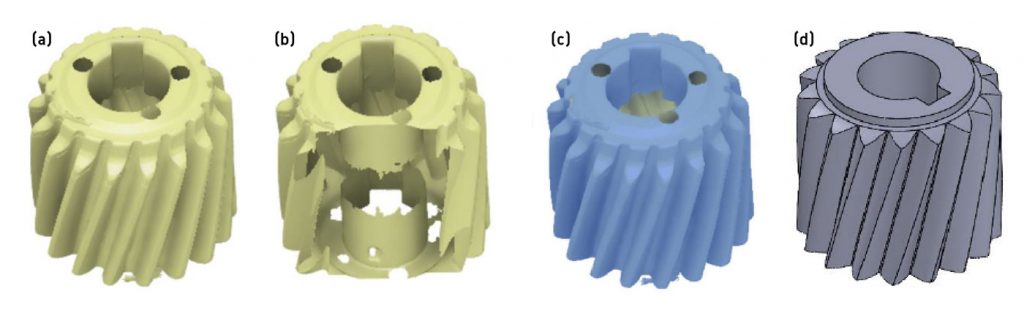
To produce a digital twin of the stainless steel helical gear part (Fig. 2a), the researchers used the blue-laser GOM ATOS Core 200 to create a 3D scan of the helical gear. As this is an optical laser, the scan was limited to surface features and unable to penetrate through features in the way X-ray CT is able to. This led to challenges in capturing geometrical details in the core areas, especially in the gear’s central shaft hole (Fig. 2b).
Repair of the scanned helical gear was performed using three different software applications: Autodesk Meshmixer, Autodesk Fusion360, and SolidWorks (Dassault Systèmes). After importing the scan data into Fusion360, the mesh body was converted into a solid. This conversion from a mesh into a solid body has different methods – faceted, prismatic and organic – each of which has its advantages and limitations. In view of its faster conversion rate, faceted mesh conversion was selected for this study (Fig. 2c). Undertaking this conversion helped patch the open surfaces of the 3D scanned data; the mesh conversion process also closed the hole of the gear intended for the rotating shaft.
A curvature analysis on the mesh revealed high curvature areas, something which would lead to significant surface roughness – a second design was necessary to prevent sharp edges. The scanned geometry was then imported into SolidWorks and used as a reference to reconstruct the helical gear; this reconstruction was then compared against the original scanned geometry for accuracy (Fig. 2d). It was noted that the redesigned gear aligned perfectly with the 3D scanned helical gear.
To further ensure the accuracy of the redesigned helical gear, the researchers additively manufactured a mirrored version of the updated helical gear using PLA filaments. The fit of this prototype was assessed to ensure the teeth aligned with the original legacy part; once the accuracy and fit of the redesigned helical gear were confirmed, the next step was to manufacture the design using metal FFF.

Based on the filament manufacturer’s Technical Data Sheet (TDS), a scaling factor of 119% was applied to the X and Y directions and 122% to the Z. In addition to the gears, ten 50 x 10 x 3.5 mm cuboids (size before scaling) were additively manufactured for characterisation purposes. Rectangular specimens (50 x 10 x 3.5 mm) were also fabricated to assess the tensile and flexural strengths. Table 1 shows the build parameters used to manufacture the redesigned helical gears.
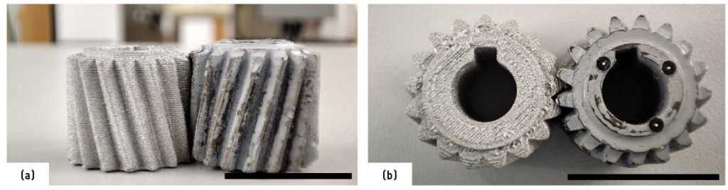
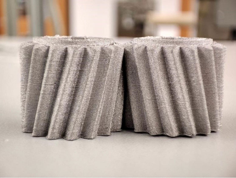
Fig. 3 shows the original helical gear part next to the redesigned and additively manufactured stainless steel gear. Fig. 4 shows the scaled-up green parts and the sintered parts. The green parts were sent to DSH Technologies LLC, USA, for debinding and sintering (the sintering profile is proprietary to BASF and cannot be disclosed in this article).

Mechanical properties analysis
Tensile and flexural strengths of the sintered specimens produced by Fused Filament Fabrication were measured using a universal testing machine (Zwick 2010, USA) with a 20 kN load cell and a crosshead speed of 0.5 mm/min. The data was analysed to determine the Ultimate Tensile Strength (UTS), flexural strength and modulus.
Results and discussion
Sintering shrinkage and density measurement
The sintered cuboids were used to determine the actual three-dimensional shrinkage, density and microstructure characteristics. The average of actual shrinkage was 17.32% in the X direction, 17.68% in the Y direction and 22.97% in the Z direction; this was slightly higher than the values provided by the post-processing partner (15.97% in the X and Y directions, and 18.03% in Z direction). The researchers expect that these measured shrinkage values will be used as future reference points.
Following binder removal, the post-sintered average weight loss for all the structures was found to be ~10.2%. The density of the sintered parts obtained using Archimedes’ principle – was 7.28 g/cm3. Notably, the Fused Filament Fabrication process – along with the post-processing – could achieve about 94% of the nominal density of 17-4 PH stainless steel (7.75 g/cm3). The researchers noted, however, that optimising AM parameters is crucial to achieving optimum densities.

Mechanical properties of the manufactured and sintered parts
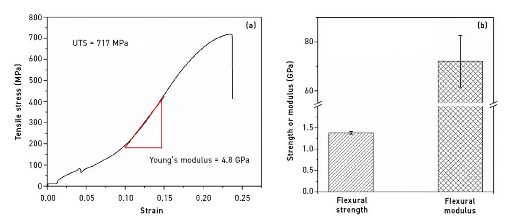
The average UTS of the sintered parts was calculated to be ~712 MPa, whereas the average tensile modulus was found to be 4.7 GPa. The tensile strength of the finished components was observed to be lower than the ingot tensile strength, generally in the range of 1360-1380 MPa [24-26]. The inferior properties compared to monolithic 17-4 PH steel primarily stem from defects produced during the FFF process, particularly the voids and porosities among the adjacent strands and between layers. The flexural strength and modulus were measured to be 1.38±0.03 GPa and 72.1±10.6 GPa, respectively. Fig. 5 shows the representative stress-strain behaviour (strength and elastic modulus) under tensile stress (a) and the flexural strength and modulus (b) obtained from three-point bending tests.
Scanning solutions
Overall, the researchers found that the intelligent deployment of Reverse Engineering and Fused Filament Fabrication, as done in this study, is effective in restoring legacy parts for which the design details were missing. An issue does arise, however, when it comes to adequate part scanning: optical, light-based 3D scanning can’t capture data on inner geometries, and the scanning method that may be most suitable isn’t always suitable.
While X-ray based computed tomography can conduct internal scans, it is not a cost-effective solution for industrial-scale manufacturing where – even without considering the cost – the overall size and shape can vary wildly. Indeed, X-ray attenuation and image acquisition can prove challenging if the legacy component is particularly large. For cases such as these, the optical laser-based scan is straightforward and can accommodate a wider variety of specimens. If inner geometries are a necessary design component, additional (even manual) reconstruction may be required to replicate these.
To overcome this pain point, the researchers worked on establishing a process flow to solve the issue of manual reconstruction with the commonly used trio of 3D modelling and CAD editing software: Autodesk Meshmixer, Autodesk Fusion360 and SolidWorks.
Characterisation
The dimensional tolerance of the redesigned gears was impressive, and they fitted well with the legacy parts still in use. The relative density of the legacy components reached approximately 94% of the theoretical, but their tensile and flexural strengths were found to be inferior compared to wrought 17-4 PH steel.
These issues can be explained by the defects ingrained in the micro- and macro-structures of the inter-strands as well as inter-layer voids and porosities. Although a 100% infill density was used during the Additive Manufacturing process, there were still visible porosities between the two adjacent strands extruded in a rectilinear pattern. When a strand had a higher length in the Z-direction, the defects were eventually suppressed/compensated by the next layers; this means that the relative density could reach an even higher value. Unfortunately, this isn’t the case for the relatively thinner flexural and tensile bars. Having a limited number of layers, there was no opportunity for the initial layer defects to be compensated, and the mechanical strength properties were measured to be inferior to the theoretical values. The manufacturing-induced defects in the coupon samples can be visualised in Fig. 6; these were consistent even after sintering.

In a follow-up study, it would be worthwhile to investigate the effect of different infill patterns on the resultant part’s strength properties. This may be especially interesting when considering that once the refurbished CAD is developed, production isn’t limited strictly to any one Additive Manufacturing process. While this study focused on Fused Filament Fabrication, the researchers note that AM technologies like Binder Jetting, Laser or Electron Beam Powder Bed Fusion would lead to higher density, better microstructure and enhanced strength properties.
It was interesting to record the higher flexural strength properties compared to the tensile properties of the sintered specimens. 17-4 PH stainless steel is precipitation-hardened martensitic steel, which exhibits compromised ductility compared to conventional 304/316 stainless steel. Having brittle behaviour, the tensile strength becomes inferior compared to the flexural strength properties (similar to ceramics). In the flexural test, the bar only experiences tensile strength to half its depth, while in the tensile strength test, the specimen experiences pure tensile forces throughout its length. As a result, fewer defects are exposed under tensile force during three-point bending, resulting in higher strength and modulus compared to the tensile strength properties.
Conclusion
Reverse Engineering and Fused Filament Fabrication successfully recreated stainless steel legacy components. The complex and intricate inner geometries of the legacy part were manually refurbished and built into the incomplete 3D scanned data. After reconstructing the completed part as a CAD file, the redesigned gears were additively manufactured using model material, PLA, to test the fit with the existing legacy component. After the successful quality test, the actual components were produced via FFF; these also demonstrated an impressive tooth-to-tooth fit with the legacy parts.
Although higher as-sintered relative density (~94%) was observed in the additively manufactured legacy components, inferior strength properties were recorded. A 100% rectilinear infill pattern was ineffective in eliminating initial inter-strand and inter-layer porosities in thinner test samples. Higher flexural strength and modulus (1.4 GPa and 72.1 GPa, respectively) were observed compared to the tensile strength and modulus (712 MPa and 4.7 GPa, respectively). These behaviours were explained in view of the composition of the material (precipitation-hardened steel) and different loading conditions in the two test types.
This study shows the effectiveness of 3D scanning, Reverse Engineering and Fused Filament Fabrication in creating digital backups of discontinued legacy components. These solutions prove worthwhile in the absence of original design files and manufacturers.
Indeed, the combination of Reverse Engineering and AM is suited to problems small – like helical gears – or mammoth: in Jurassic Park III (2001), the nasal resonating chamber of a raptor was reverse-engineered and additively manufactured, allowing the team to survive!
Acknowledgements
The authors would like to sincerely thank Jerry Morgan (Monticello Tool and Die) for providing the legacy parts, Sheila Martin (Association of Public and Land Grant Universities) for helping in the funding for the NIST-APLU grant, Scott Broughton as the MEP partner for bringing together the companies and William Metcalf for leading industry outreach coordination effort that enabled the team to collaborate with the industry, MEP and the University. The authors are also indebted to the Small Business Administration (SBA) for providing funding to support the 3D printing accelerator program at the UofL. Funding for this work was sponsored by the Minority Business Development Agency grant MB21OBD8020222.
Authors
Sihan Zhang1, Saleh Khanjar1, Srimanta Barui1, Kameswara Pavan Kumar Ajjarapu1, Lauren Shackleford2, Andrew Pierce3, and Kunal Kate1
1University of Louisville, KY, USA
2University of Kentucky, KY, USA
3GE Appliances, USA
Contact
Kunal Kate
[email protected]
Srimanta Barui
[email protected]
References
[1] S. Khanjar, Digital design and thermomechanical process simulation for 3D printing with ABS and soyhull fibers reinforced ABS composites, Mechanical Engineering, University of Louisville, 2021.
[2] M.Q. Shaikh, S.D. Nath, A.A. Akilan, S. Khanjar, V.K. Balla, G.T. Grant, S.V. Atre, Investigation of Patient-Specific Maxillofacial Implant Prototype Development by Metal Fused Filament Fabrication (MF3) of Ti-6Al-4V, 9(10) (2021) 109.
[3] M.Q. Shaikh, P.-Y. Lavertu, K.H. Kate, S.V. Atre, Process Sensitivity and Significant Parameters Investigation in Metal Fused Filament Fabrication of Ti-6Al-4V, Journal of Materials Engineering and Performance 30(7) (2021) 5118-5134.
[4] P. Singh, V.K. Balla, S.V. Atre, R.M. German, K.H. Kate, Factors affecting properties of Ti-6Al-4V alloy additive manufactured by metal fused filament fabrication, Powder Technology 386 (2021) 9-19.
[5] K. Sudan, P. Singh, A. Gökçe, V.K. Balla, K.H. Kate, Processing of hydroxyapatite and its composites using ceramic fused filament fabrication (CF3), Ceramics International 46(15) (2020) 23922-23931.
[6] P. Singh, V.K. Balla, A. Gokce, S.V. Atre, K.H. Kate, Additive manufacturing of Ti-6Al-4V alloy by metal fused filament fabrication (MF3): producing parts comparable to that of metal injection molding, Progress in Additive Manufacturing 6(4) (2021) 593-606.
[7] K.P.K. Ajjarapu, C. Barber, J. Taylor, T. Pelletiers, D. Jackson, C. Beamer, S.V. Atre, K.H. Kate, Advancements in 3D printing and hot isostatic pressing of copper: bridging the gap between green and sintered states for enhanced mechanical and electrical properties, Progress in Additive Manufacturing (2024).
[8] S. Barui, A.K. Panda, S. Naskar, R. Kuppuraj, S. Basu, B. Basu, 3D inkjet printing of biomaterials with strength reliability and cytocompatibility: Quantitative process strategy for Ti-6Al-4V, Biomaterials 213 (2019) 119212.
[9] S. Barui, D. Mishra, N.H. Gowtham, B. Basu, No more ‘core-shell’ in binderjetting of bioceramics: Novel solution and experimental validation in microstructure and mechanical properties, Journal of the European Ceramic Society 43(3) (2023) 1178-1188.
[10] S. Barui, S. Chowdhury, R. Samajdar, S. Chakraborty, M. Gavade, B. Basu, Impact of ‘core-shell’ mode of printing on properties of 3D binderjet printed zirconia-alumina based bioceramics, Open Ceramics 3 (2020) 100026.
[11] F. Bartolomeu, M. Sampaio, O. Carvalho, E. Pinto, N. Alves, J.R. Gomes, F.S. Silva, G. Miranda, Tribological behavior of Ti6Al4V cellular structures produced by Selective Laser Melting, Journal of the Mechanical Behavior of Biomedical Materials 69 (2017) 128-134.
[12] K. Wissenbach, S. Höges, P. Robotti, A. Molinari, L. Facchini, E. Magalini, Ductility of a Ti‐6Al‐4V alloy produced by selective laser melting of prealloyed powders, Rapid Prototyping Journal 16(6) (2010) 450-459.
[13] M. Koike, K. Martinez, L. Guo, G. Chahine, R. Kovacevic, T. Okabe, Evaluation of titanium alloy fabricated using electron beam melting system for dental applications, Journal of Materials Processing Technology 211(8) (2011) 1400-1408.
[14] L.E. Murr, E.V. Esquivel, S.A. Quinones, S.M. Gaytan, M.I. Lopez, E.Y. Martinez, F. Medina, D.H. Hernandez, E. Martinez, J.L. Martinez, S.W. Stafford, D.K. Brown, T. Hoppe, W. Meyers, U. Lindhe, R.B. Wicker, Microstructures and mechanical properties of electron beam-rapid manufactured Ti–6Al–4V biomedical prototypes compared to wrought Ti–6Al–4V, Materials Characterization 60(2) (2009) 96-105.
[15] L. Li, F. Yu, J. Shi, S. Shen, H. Teng, J. Yang, X. Wang, Q. Jiang, In situ repair of bone and cartilage defects using 3D scanning and 3D printing, Scientific Reports 7(1) (2017) 9416.
[16] Q. Jiang, X. Feng, Y. Gong, L. Song, S. Ran, J. Cui, Reverse modelling of natural rock joints using 3D scanning and 3D printing, Computers and Geotechnics 73 (2016) 210-220.
[17] S.D. Laycock, G.D. Bell, N. Corps, D.B. Mortimore, G. Cox, S. May, I. Finkel, Using a Combination of Micro–Computed Tomography, CAD and 3D Printing Techniques to Reconstruct Incomplete 19th-Century Cantonese Chess Pieces, 7(4 %J J. Comput. Cult. Herit.) (2015) Article 25.
[18] A.J. CRESSWELL-BOYES, A.H. BARBER, D. MILLS, A. TATLA, G.R. DAVIS, Approaches to 3D printing teeth from X-ray microtomography, 272(3) (2018) 207-212.
[19] P. Wang, J. Yang, Y. Hu, J. Huo, X. Feng, Innovative design of a helmet based on reverse engineering and 3D printing, Alexandria Engineering Journal 60(3) (2021) 3445-3453.
[20] G. Baronio, S. Harran, A. Signoroni, A Critical Analysis of a Hand Orthosis Reverse Engineering and 3D Printing Process, Applied Bionics and Biomechanics 2016 (2016) 8347478.
[21] B. Basu, N. Bhaskar, S. Barui, V. Sharma, S. Das, N. Govindarajan, P. Hegde, P.J. Perikal, M. Antharasanahalli Shivakumar, K. Khanapure, A. Tekkatte Jagannatha, Evaluation of implant properties, safety profile and clinical efficacy of patient-specific acrylic prosthesis in cranioplasty using 3D binderjet printed cranium model: A pilot study, Journal of Clinical Neuroscience 85 (2021) 132-142.
[22] R.H. Helle, H.G. Lemu, A case study on use of 3D scanning for reverse engineering and quality control, Materials Today: Proceedings 45 (2021) 5255-5262.
[23] N. Kladovasilakis, T. Kontodina, P. Charalampous, I. Kostavelis, D. Tzetzis, D. Tzovaras, A case study on 3D scanning, digital reparation and rapid metal additive manufacturing of a centrifugal impeller, IOP Conference Series: Materials Science and Engineering 1037(1) (2021) 012018.
[24] s.s. 17-4, https://en.wikipedia.org/wiki/17-4_stainless_steel.
[25] A. Caballero, J. Ding, S. Ganguly, S. Williams, Wire + Arc Additive Manufacture of 17-4 PH stainless steel: Effect of different processing conditions on microstructure, hardness, and tensile strength, Journal of Materials Processing Technology 268 (2019) 54-62.
[26] P. Ponnusamy, B. Sharma, S.H. Masood, R.A. Rahman Rashid, R. Rashid, S. Palanisamy, D. Ruan, A study of tensile behavior of SLM processed 17-4 PH stainless steel, Materials Today: Proceedings 45 (2021) 4531-4534.