


The Additive Manufacturing of multi-material and multi-functional ceramic components
Additive Manufacturing’s high geometric flexibility, when combined with the optimised properties of multi-material components, opens up new possibilities for designers and manufacturers. Recently, innovations in the design of the interfaces between different materials presents further opportunities with regard to the functionalisation and miniaturisation of components. In this article, Uwe Scheithauer, Fraunhofer IKTS, and Robert Johne, AMAREA Technology GmbH, explore the potential in the area of ceramic-based components produced using Multi Material Jetting (MMJ) technology. [First published in PIM International Vol. 18 No. 1, Spring 2024 | 30 minute read | View on Issuu | Download PDF]
![Fig. 1 Allocation of materials in a traditional composite (left) and a Functionally Graded Material (FGM) composite (right) [1]](http://www.pim-international.com/wp-content/uploads/sites/2/2025/01/cover-image-1024x581.jpg)
Two points essentially determine the behaviour of components: the material used and the geometric shape.
The material used
The physical and chemical properties of a component are defined by the material used. If a component consists of only one material, it has the same properties in all areas. As an important part of a component’s design process, a suitable material is selected from one of the many material classes according to the requirements of the application scenario. Depending on whether the choice falls on polymers, metals, ceramics or glass, the physical and chemical properties of the component differ significantly.
Polymer materials, for example, are notable for their low density, ease of production and very good machinability. In contrast, the production of ceramic components is much more complex due to the longer process chain, including thermal processing. However, ceramic components are significantly more resistant to chemical, thermal or mechanical stress, even compared to metals.
In an increasingly complex world, more and more challenging application scenarios are emerging in which combinations of material properties are required that do not exist in a single material. The following list contains some combinations of properties for more complex applications:
- Electrically conductive & insulating
- Thermally conductive & insulating
- Hard & ductile
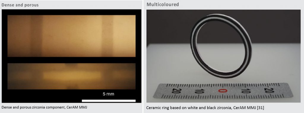
- Dense & porous
- Magnetic & non-magnetic
- Multi-coloured
- A combination of different property combinations
When single materials do not deliver the desired combination of properties, it becomes necessary to blend different materials in order to achieve the desired properties within a single component. Conventional composites, depicted in Fig. 1(a), consist of homogeneous mixtures. However, this often leads to compromises between the desirable properties of the individual component materials. In contrast, Functionally Graded Material (FGM) composites represent an even more advanced class of materials.
FGMs exhibit spatially varying material composition along a changing dimension (Fig. 1(b)), resulting in corresponding variations in material properties that are inherently built-in. By mapping strategies of allocating and structuring materials to the desired performance requirements, multifunctionality can be created in a component.

The following types of grading can be distinguished for FGMs:
Discontinuous grading
The component has discrete areas with different properties, wherein either material A or material B is present.
Gradient interface
There is a special intermediate layer between the two areas with different properties to create a smooth transition zone. Within this intermediate layer there is one mixture of materials A and B.
Gradual grading
The component has different discrete layers with different properties that are arranged in stages. Within a layer, the ratio between material B and material A is constant. As the number of layers increases, the difference in properties between the individual layers can be reduced.
Continuous grading
The component has a continuous variation of properties over the entire cross-section. The ratio between material B and material A increases or decreases continuously.
In some cases, it is not necessary to use two or more different materials. Instead, a single material can be employed in distinct states. For instance, it can serve as a dense structure in some areas and as a porous structure in others. This can be realised by varying the process parameters in Additive Manufacturing, for example, by varying the distance between the material deposits to generate areas with less, or no, material – and thus pores – in the subsequent component. Another example involves combining the same material but with different colours within a single component.

Component shape
Geometric functionalisation refers to the modification of the shape of a component in order to achieve certain functional properties. The shape, surface structure or microstructure of the material can be specifically modified in order to achieve specific properties (mechanical, optical, electrical, etc.). One example of geometric functionalisation is the use of surface structures, such as micro- or nanostructures, to improve the adhesion, friction or wettability of a material. Another possibility is to change the pore structure of a material in order to optimise its absorption or filtration properties.
Geometric functionalisation is used in various areas, such as lightweight construction (implementation of ribs and struts to increase rigidity and strength or the integration of cavities to reduce component mass), filtration technology or heat exchangers (increasing the exchange surface), biotechnology (targeted modification of wetting properties), toolmaking (integration of near-contour cooling channels) or gear technology (tooth profiles or gearing to optimise power transmission).
In the field of geometric functionalisation, the emergence of various technologies from the field of Additive Manufacturing has opened up a previously unrealised degree of freedom. As a result of the layered structure of the components during production, undercut, highly complex, or otherwise intricate geometries can be realised. These could not previously be achieved using methods such as casting, milling, drilling or eroding – or only at extreme expense. In addition, tool-free production via AM enables the flexible realisation of a wide variety of geometries in a very short time, so that iteration cycles can be significantly shortened.
Additive Manufacturing of multi-material and multi-functional components
Current work is concerned with the development of processes and the associated device and process technology for the Additive Manufacturing of multi-material and multi-functional components. The combination of high geometric flexibility through Additive Manufacturing, and the optimised properties of multi-material components, opens up completely new possibilities for component designers and developers, not only in component design in general, but also in the design of interfaces between different materials. This results in disruptive innovations in a wide range of application areas, particularly with regard to the functionalisation and miniaturisation of components. From here, this article considers the potential in the area of ceramic-based components.
Special features of the ceramic process chain
Ceramic materials are used where other materials fail. They are characterised by outstanding thermal, chemical and mechanical properties, and also have a high lightweight engineering potential compared to many metals due to their relatively low density and high rigidity. Their good electrical insulation properties are also of interest for many applications, which is why ceramic materials are often used in high-voltage technology.
The challenges of the ceramic process chain result primarily from the final two-stage thermal processing. Firstly, all non-ceramic components of the feedstock that were necessary for shaping must be removed during debinding in order to enable complete densification and the formation of the expected ceramic properties during sintering. This also applies to additively manufactured ceramic components, as the various AM technologies used almost exclusively result in a green body.
As maximum temperatures of over 1500°C and shrinkage in the range of 50% by volume are not uncommon during sintering, there are two main challenges during the sintering of multi-material components. Firstly, only materials with similar coefficients of thermal expansion (CTE) can be processed together, as thermally induced stresses can lead to either deformities or deformation. This is due to a mismatch during cooling after sintering which can lead to failure in operation. In addition, the materials must have similar shrinkage behaviour, otherwise defects will be generated during sintering.

Examples of ceramic-based multi-material components
Figs. 2-5 show various examples in which ceramic-based multi-material components have been realised without AM technologies. Materials with comparable CTE were combined with each other and their shrinkage behaviour was adapted accordingly.
Electrically conductive and insulating
![Fig. 2 Left: ceramic glow plug (CIM) [2]. Right: pressure sensor, hybridisation of multilayer technology and CIM [3]](http://www.pim-international.com/wp-content/uploads/sites/2/2025/01/f02-web-4-1024x298.jpg)
Hard and ductile
![Fig. 3 Top left: alumina toughened zirconia (ATZ)/zirconia toughened alumina (ZTA) CIM components [4], top right: ZrO2 and stainless steel via CIM [5], bottom left: ZrO2 and stainless steel, multilayer [6], bottom right: cutting tools based on ZrO2 and stainless steel, multilayer [7]](http://www.pim-international.com/wp-content/uploads/sites/2/2025/01/f03-web-2-1024x434.jpg)
Multi-coloured
![Fig. 4 Left: CIM hardmetal-cermet combination [10], right: jewellery components, In-mould-labeling (tape and CIM) [11]](http://www.pim-international.com/wp-content/uploads/sites/2/2025/01/f04-2-1024x306.jpg)
Different porosities
![Fig. 5 Left: Filters, extrusion and coating, middle: filters based on ZrO2 and stainless steel, multilayer/tape casting [8], right: refractories with multilayer graded porosity [9]](http://www.pim-international.com/wp-content/uploads/sites/2/2025/01/f05-2-1024x281.jpg)
CerAMfacturing = the AM of ceramics
The qualification of ceramic materials for various Additive Manufacturing technologies enables the production of parts with an unprecedented level of geometric complexity. For ceramic materials, which are extremely hard and also very difficult to machine due to their brittle fracture behaviour, AM technologies are game-changing manufacturing technologies. Highly complex geometries can be realised for the first time, or with significantly less effort, as post-processing is reduced or even completely eliminated. Additively manufactured ceramics are now a real alternative to components made of polymers and metals, especially for applications in harsh conditions.
The AM technologies used for ceramic materials are used almost exclusively as pure shaping technologies for the manufacturing of green bodies [12–14]. Consequently, all AM technologies known and used for polymers can also be used for the realisation of ceramic green bodies. The main difference is that the starting materials for the respective AM technology have a very high loading of ceramic particles. Typical values are in the range between 40 and 60% by volume.
With regard to the large number of different AM technologies, we refer here to the relevant standards [15], VDI guidelines [16,17] and review papers [12–14]. To avoid confusion with the AM of polymers, we at IKTS use the term CerAMfacturing (=AM of ceramics) and add the prefix CerAM to the various technologies.
Direct and indirect AM technologies
The various AM technologies can all be differentiated, for example, according to the type of starting material (e.g. granulate, suspension, filament) or consolidation (e.g. binder application, cross-linking, cooling). However, the type of material application is particularly important for the realisation of multi-material components. Zocca et al. [12] proposed a subdivision into direct and indirect AM technologies.
In indirect AM technologies, the starting material is applied over the entire surface of the installation space before selective consolidation of the starting material takes place, i.e. only in the areas that are required for the generation of the component in this layer. Typical examples are the AM technologies from the process classes Binder Jetting (BJT), Powder Bed Fusion (PBF) or Vat Photopolymerisation (VPP).
With direct AM technologies, the starting material is only deposited and consolidated where this is needed to create the current layer. This means that it is not necessary to remove the first unconsolidated starting material before another starting material can be deposited. Typical representatives are AM technologies from the Material Extrusion (MEX) and Material Jetting (MJT) process classes, in which different starting materials can be deposited directly next to each other using different dosing systems.
AM of multi-materials with indirect processes
Indirect AM technologies for ceramic materials offer large, scalable build spaces and high productivity (e.g. BJT, PBF) or very good component properties in terms of density, manufacturing tolerances and surface quality as well as maximum resolution (VPP). Commercial systems that have been specially developed for ceramic materials are mainly available in the VPP process class. The best-known suppliers are Lithoz (Austria), 3DCeram (France) and Admatec, now part of Nano Dimension (Netherlands). The portfolio of materials for these technologies is also growing and now includes not only Al2O3 and ZrO2, but also Si3N4 and AlN and many more [18–23].
Scientific work on AM of multi-materials based on VPP has been published primarily for Lithoz’s machine technology, which is commercialised under the name Lithography-based Ceramic Manufacturing (LCM) [24]. In the multi-material 2M30 machine, which was used for the following study, two different vats are used for the different starting materials, which can be moved alternately between the building platform (which can only be moved in the z-direction) and the stationary exposure unit. When changing between the vats or materials, a cleaning step is carried out to remove any non-crosslinked suspension still adhering to the component surfaces and to avoid cross-contamination between the vats.
![Fig. 6 Schematic of the multi-material approach by Schlacher et al. (top) compared to pure Al2O3 disks (below) [25]](https://www.pim-international.com/wp-content/uploads/sites/2/2025/01/f06-2-edited.jpg)
The improvement of the mechanical properties was addressed in an article by Schlacher et al. [25]. The paper presents additively manufactured alumina disks with excellent biaxial strength using the ‘layer-by-layer’ capability of LCM technology. A multi-material approach enabled the combination of alumina-zirconia layers between pure alumina layers, which introduced significant residual compressive stresses into the latter as a result of the different CTEs during cooling after sintering (Fig. 6). A characteristic strength of more than 1 GPa was measured for the alumina multi-material system, compared to ~650 MPa for monolithic alumina, which serves as a reference.
![Fig. 7 Alumina component with graded porosity [27]](http://www.pim-international.com/wp-content/uploads/sites/2/2025/01/f07-2.jpg)
Alumina samples exhibiting graded porosities are described in another article by Nohut et al. [26,27]. This was realised by combining two suspensions, to one of which a PMMA content of 20% was added as a sacrificial pore former. This made it possible to investigate the effects of the PMMA content on the resulting porosity, microstructure and mechanical properties. Fig. 7 shows an alumina component on a light source. This appearance results from the graded porosity and the refraction and scattering of light at the pores. [27]
AM of multi-materials with direct processes
Probably the best-known example of direct AM technologies is Fused Filament Fabrication (FFF), from the Material Extrusion (MEX) class of AM processes. Here, a thermoplastic filament is fed into a nozzle, melted, and applied. Solidification takes place purely via cooling, so that there are virtually no limitations in terms of the powders that can be processed. Different materials can be combined in one component using different nozzles, each of which processes a different filament.
In the field of ceramic materials, this has already been realised for combinations of electrically conductive and electrically insulating material mixtures based on Si3N4 and MoSi2. Fig. 8 shows a component for a heater application during a functional test. The two different mixtures are matched in such a way that comparable shrinkage properties and thermal expansion coefficients are achieved. This work was a collaboration between PolyMerge, Tiwari Scientific Instruments and Fraunhofer IKTS [28]. An almost identical material pairing was also qualified for Multi Material Jetting (MMJ), an AM technology from the MJT class, and is described in detail below.

Multi Material Jetting (MMJ)
Multi Material Jetting (MMJ) occupies a unique position in the AM landscape with its capability for multi-material Additive Manufacturing (MMAM). Positioned between Fused Filament Fabrication (FFF) and stereolithography-based VPP, MMJ bridges the gap by combining favourable feedstock properties with an innovative shaping logic.
MMJ was first developed in 2014 at Fraunhofer IKTS Dresden. Since then, a wealth of knowledge and experience has been gained and demonstrated with more than fifteen materials and material combinations qualified for use on MMJ-based multi-material AM machines. These in-house-developed AM machines produced convincing prototype components, serving a diverse range of industrial customers, but the journey of MMJ did not end there.
As part of the Fraunhofer-Gesellschaft’s commitment to applied research and translating technological breakthroughs into tangible benefits for the economy and society, researchers from Fraunhofer IKTS (Fig. 9), supported by the German Federal Ministry for Economic Affairs and Climate Protection (BMWK) through the EXIST research transfer funding programme, founded AMAREA Technology GmbH in February 2023 [29]. The Dresden-based company’s mission is to commercialise MMJ by transitioning the cutting-edge AM machines and materials into series production for use in industrial manufacturing [30].

In MMJ, the feedstocks are low-viscosity thermoplastic suspensions that contain the material as a powder – a different feedstock contains a different material powder or powder mixture. Remarkably, MMJ feedstocks accommodate high solid-loading levels, ranging from at least 40% to beyond 50% volume, using a diverse array of ceramic powders, regardless of their material characteristics or optical properties [31–33]. This versatility extends from ceramics, such as, among others, black and white zirconia, alumina, and silicon nitride to glass, metals, hardmetals and cermets [32–35] [MMJ02-05]. Technically, almost any powder can be used in a MMJ feedstock, depending on the powder properties and the specific desired material properties – one of the two features, making MMJ capable of MMAM.
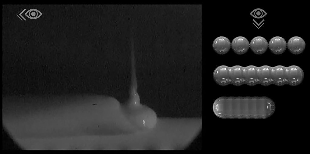
MMJ’s second important feature for MMAM lies in its unique shaping logic. In MMJ, a feedstock is selectively deposited as single droplets using a piezoelectric micro dispensing system. These tiny droplets precisely fuse together in the x-y direction, forming filament-like structures (Fig. 10), which can then be fused to form flat structures.
Ultimately in the z-direction, the process of stacking and fusing together results in the creation of intricate 3D objects. The small dimensions of these nanolitre-sized droplets allow for exceptional resolution in the range of a few hundred micrometres. Altering the micro dispensing parameters enables a controlled flexibility in droplet resolution. The deposition rate can be increased up to 800 droplets a second.
Multiple micro dispensing systems, each loaded with a distinct feedstock containing a different powder composition, allow diverse materials to be deposited next to and on top of one another building a multi-functional component during a single build job. Sagging and collapse of large overhangs are prevented by adding support material as a temporary element during the shaping. The overall spatial control of MMJ enables not only MMAM, but also functionally graded AM.
A preview of AMAREA Technology’s multi-material AM machine
To further expand the possibilities of multi-material and functionally graded AM, the MMJ-based system technology is being constantly evolved.
Starting from the three print heads (micro dispensing systems) in Fraunhofer IKTS’s demonstration machine, i.e. up to three different materials that can be used in an additive build job, the number of print heads and thus co-3D-printable materials has already been increased up to six, as AMAREA Technology shows in the preview of its first series industrial multi-material AM machine.

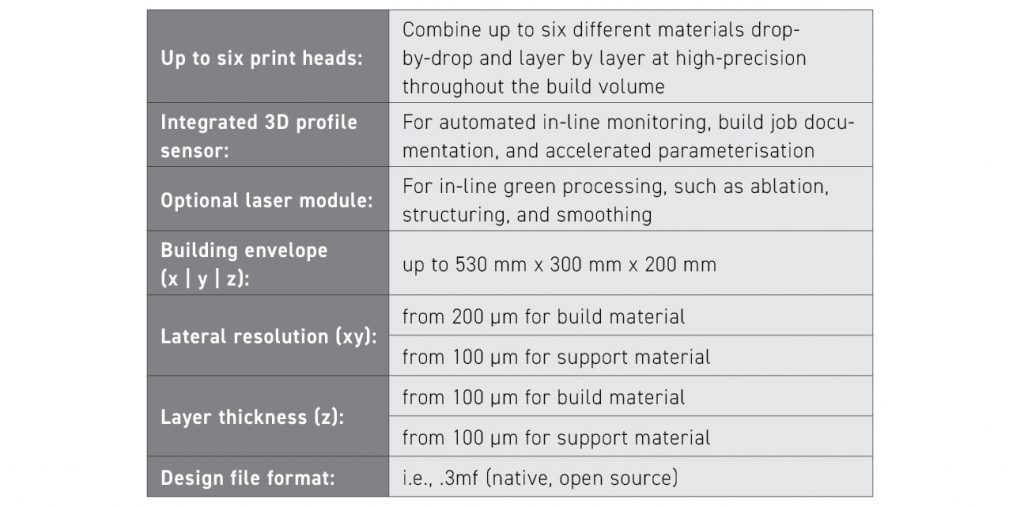
The MMJ Pro System is a modular and upgradable industrial AM machine with tailored control software (Fig. 11). In addition to the (up to six) print heads, a 3D profile sensor for automated in-line monitoring, build job documentation, and accelerated parameterisation is included as standard. The system is designed to also work with particularly hard materials, such as those typically used for technical ceramic applications. Because of their hardness, the machining of sintered components is very costly.
For this reason, an optional laser module will be offered for the system in the future. The laser will not only enable the smoothing of outer surfaces to a surface roughness as low as, or even below, 1 µm Ra, as demonstrated during test runs in the past, but, in the future, also enable the targeted ablation and defined in-line structuring of the individual layers of the green body for a hybridised additive-subtractive processing during shaping. This will not only further improve manufacturing tolerances, but also ensure the customised design of the interface between different materials. Table 1 summarises the technical properties of AMAREA Technology’s modular MMJ Pro System.
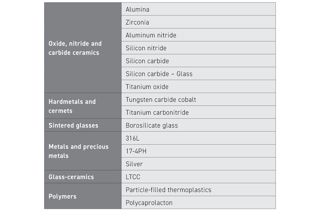
Materials for MMJ
Over almost a decade of material development, the range of materials used with the MMJ technology has grown steadily. The wide range of materials is summarised in Table 2. The ability to utilise virtually any powder for MMJ feedstock production enables Fraunhofer IKTS and AMAREA Technology to rapidly expand their portfolio beyond its current state. Interested companies can provide the powder, and with the assistance of Fraunhofer IKTS and AMAREA Technology, have a customised feedstock tailored to their specific needs. AMAREA Technology refers to this service as Bring Your Own Powder, or BYOP. Additionally, if the appropriate materials have not yet been identified, the partners can assist in identifying and sourcing them for customisation.
MMJ case study: Temperable tool for forming applications
While the technical details of MMAM and the MMJ technology may not immediately reveal the full extent of its benefits beyond component functionality and performance, a specific real-world example – along with the associated requirements and the solution through MMJ – can illuminate its overall advantages.
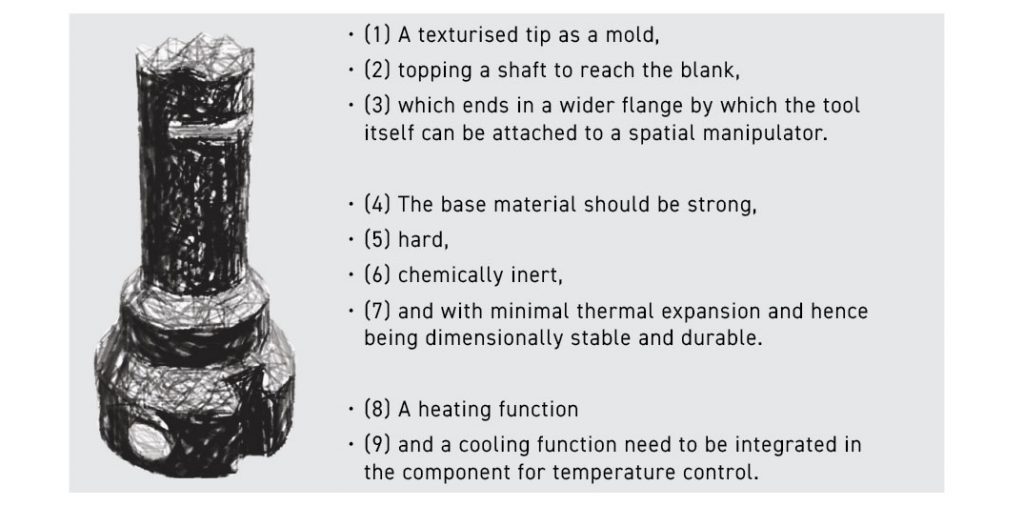
For that purpose, an application is envisioned where a ‘temperable’ tool for a forming solution is needed. It is rather a common theme in real-world forming processes where something needs to be formed to have heating or cooling involved as part of the process and to adapt the temperature as a means of process control. The requirements of such a tool are summarised in Fig. 12, which depicts a mock-up design sketch for such a temperable tool’s requirements.

The component’s multi-material design, including shape and materials, is shown in Fig. 13. Fig. 14 shows an example component actually manufactured by MMJ including consecutive debinding and sintering during testing of the heating function. This component demonstrates how well the additively manufactured multi-material design meets the following requirements:
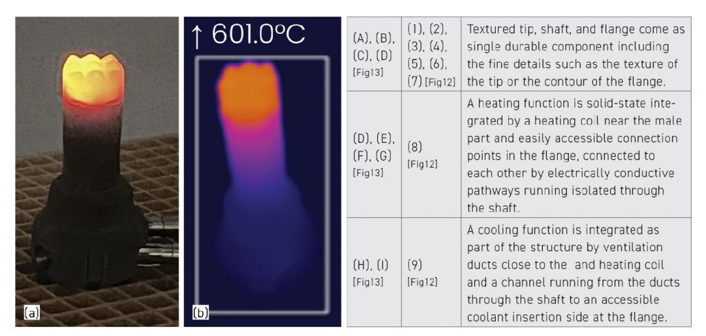
A single, durable and complex component
The textured tip, shaft, and flange come as a single durable component including fine details such as surface texture or the contour of the flange (design features (A) – (D), meeting requirements (1) – (7)).
Integrated heating function
A heating function is solid-state integrated by a heating coil in the immediate vicinity of the textured tip and easily accessible connection points in the flange, both of which are connected to each other via insulated electrically conductive pathways running through the shaft (design features (D) – (G) meeting requirement (8)).
Integrated cooling function
A cooling function is integrated as part of the structure through ventilation ducts near the textured tip and the heating coil as well as a channel running from the ducts through the shaft to an accessible coolant inlet side on the flange. (design features (H), (I) meeting requirement (9)).
Other less obvious user benefits for the temperable tool case study are as follows:
A fast, efficient, safe and strong design
The heating coil is spiral-shaped and positioned close to the textured tip. Its design ensures fast, efficient, and safe heating. As it is a solid-state integrated heating coil, it minimises the risk of degradation and fire hazards associated with its function. Additionally, the coil heats locally where needed, and the specific geometry acts as a semi-decoupling mechanism to other areas of the component. This minimises heat transfer to the rest of the component including all attachments, e.g. when the component is attached to a spatial manipulator on the flange.
Integrated conductive pathways
The integrated conductive pathways are designed to run inside the shaft as a solid-state conductor. This configuration ensures both safety and reliability. By incorporating the conductive pathways directly into the shaft, the risk of fire hazards is minimised, and damage or degradation of the conductive and insulation performance is prevented, especially when compared to traditional cable wiring methods.
Integrated electrical connection
Integrated electrical connection points are designed with connectors as part of the flange. This configuration ensures easy accessibility to connection points for power supply. By incorporating the connectors directly into the flange, users can conveniently establish electrical connections without the need for additional components or complex wiring.
Integrated ventilation
Integrated ventilation ducts and a supply channel are strategically positioned close to the textured tip and heating coil, with the channel running inside the shaft. This design ensures efficient, reliable, and easily accessible cooling. The cooling is localised to where it is needed, minimising heat transfer to the mounting (effectively creating an ‘air-conditioned’ shaft) and providing shielding for other areas of the component. Additionally, an easily accessible interface is provided for coolant supply.
Conclusions
The case study only uses multiple materials in a single, dense state. Considerable unexplored opportunities exist to employing materials in distinct states. For instance, in addition to dense areas, porous structures could serve to provide additional heat shielding in other areas. MMAM opens up completely new freedoms in component design, and MMJ technology is one of the pioneers here. The following is a summary of the overall benefits using MMJ:
A multitude of diverse functions
A multitude of diverse functions stemming from contrasting material properties, such as electrically conductive and non-conductive behaviour, among others, can be integrated into a single component. This can lead to the production of innovative components that were previously impossible to produce with only a single material.
The functionalities of an assembly without a need to assemble
Multi-material components are not only realisable but also provide the functionalities of an assembly without the actual need to assemble – eliminating the need for complex, time-consuming, and design restricting joining methods. MMJ can, therefore, reduce complex production pipelines for assemblies through the MMAM of an assembly as a single component in a single build job.
MMAM integrates functions without the need for assembly or joining and pairs it with the capability of scaling dimensions. This leads to the integration of more functions, often requiring a miniaturisation approach, which MMJ delivers as a single build job. Furthermore, with the ability to design and scale interfaces according to a component’s added functionality and its application environment, using MMJ enables the production of the specific connection interfaces.
Design iterations
Adapting the design and going through design iterations for MMAM is primarily a digital process. ‘Design for MMJ’ speeds up the engineering, prototyping, and testing phases and saves resources along the way.
The possibility to not only adapt the design in terms of shape, but also the materials, enables other material combinations to be used if it becomes necessary or is advantageous in future product interactions. Hence, when an operating environment changes, far more than just shape requirements can change. MMJ can provide solutions with other material combinations.

Figs. 15 and 16 show further MMAM components based on ceramic materials and the corresponding literature references. This is just a small selection, without any claim to completeness, which represents the beginning of a fantastic journey.
The challenge and opportunity now is to think in a completely new way. For the different application scenarios, the required functionalities and the real existing boundary conditions (not the limitations that exist in people’s minds) must be identified and compared with the possibilities of the materials and production technologies. And even if it may not yet be possible to realise the required component, it is important to always remember how quickly the world is changing and technologies are developing.
Authors
Dr.-Ing. Uwe Scheithauer
Fraunhofer-Institut für Keramische Technologien und Systeme IKTS
[email protected]
www.ikts.fraunhofer.de
Robert Johne,
AMAREA Technology GmbH
[email protected]
www.amarea.de
References
[1] “ISO/ASTM TR 52912:2020: Additive manufacturing – Design – Functionally graded Additive Manufacturing,”.
[2] Eveline Zschippang, Anne Mannschatz, Hagen Klemm et al., “Charakterisierung und Verarbeitung von Si3N4-SiC-MoSi2-Kompositen für Heisleiteranwendungen,” Keramische Zeitschrift, no. 5, pp. 294–297, 2013.
[3] Steffen Ziesche, Christian Lenz, Axel Müller-Köhn, “Mehrlagenkeramik und Keramikspritzguss – eine technologische Kombination zur Herstellung dreidimensionaler funktioneller Keramikkomponenten.,” Keramische Zeitschrift, vol. 69, pp. 29–33, 2017.
[4] A. Mannschatz, Tassilo Moritz, Stephan Jegust et al., “Enabling Co-Sintering of ATZ/ZTA Ceramic Compounds by Two- Component Injection Moulding with Green Tapes as Interlayers,” Powder Metallurgy Conference Euro PM 2011, 2011.
[5] A. Baumann, T. Moritz, and R. Lenk, “Multi component powder injection moulding of metal-ceramic-composites,” International Powder Metallurgy Congress & Exhibition : EPMA, 2009, 2009.
[6] A. Günther, T. Moritz, and U. Mühle, “Microstructure and Interface Characteristics of 17-4PH/YSZ Components after Co-Sintering and Hydrothermal Corrosion,” Ceramics, vol. 3, no. 2, pp. 245–257, 2020.
[7] T. Slawik, A. Günther, U. Scheithauer et al., “Adapting the co-sintering behaviour of metal-ceramic composites,” 2015.
[8] T. Slawik, A. Bergner, R. Puschmann et al., “Metal–Ceramic Layered Materials and Composites Manufactured Using Powder Techniques,” Advanced Engineering Materials, vol. 16, no. 10, pp. 1293–1302, 2014.
[9] K Haderk, U Scheithauer, HJ Richter, U Petasch, “Development of ceramic tapes for thermal shock resistant calcium aluminate refractory materials with graded porosity,” Interceram, 2011.
[10] Anne Mannschatz, S. Szokup, A. Müller-Köhn, J. Pötschke, T. Moritz, A. Michaelis, S. Jegust, M. v. Witzleben, “Co-Sintering of Cermet and Black Zirconia for Aesthetic Products.,” Proceedings EuroPM 2021, 2021.
[11] A. Mannschatz, A. Härtel, A. Müller-Köhn et al., “Manufacturing of two-colored co-sintered zirconia components by inmold-labelling and 2C-injection molding.,” Ceramic forum international, vol. 91, E53-E58, 2014.
[12] A. Zocca, P. Colombo, C. M. Gomes et al., “Additive Manufacturing of Ceramics: Issues, Potentialities, and Opportunities,” Journal of the American Ceramic Society, vol. 98, no. 7, pp. 1983–2001, 2015.
[13] Z. Chen, Z. Li, J. Li et al., “3D printing of ceramics: A review,” Journal of the European Ceramic Society, vol. 39, no. 4, pp. 661–687, 2019.
[14] N. Travitzky, A. Bonet, B. Dermeik et al., “Additive Manufacturing of Ceramic‐Based Materials,” Advanced Engineering Materials, vol. 16, no. 6, pp. 729–754, 2014.
[15] ISO/ASTM, “Additive manufacturing – General principles – Fundamentals and vocabulary (ISO/ASTM 52900:2022-03),”.
[16] VDI, “Additive manufacturing processes – Design rules – Parts using ceramic materials,” 2021-11, VDI 3405 Part 8.1.
[17] VDI, “Additive manufacturing processes – Test specimens for ceramic parts,” 2023-05, VDI 3405 Part 8.2.
[18] M. Schwentenwein and J. Homa, “Additive Manufacturing of Dense Alumina Ceramics,” International Journal of Applied Ceramic Technology, vol. 12, no. 1, pp. 1–7, 2015.
[19] J. Stampfl, M. Schwentenwein, J. Homa et al., “Lithography-based Additive Manufacturing of ceramics: Materials, applications and perspectives,” MRS Communications, vol. 13, no. 5, pp. 786–794, 2023.
[20] E. Zanchetta, M. Cattaldo, G. Franchin et al., “Stereolithography of SiOC Ceramic Microcomponents,” Advanced materials (Deerfield Beach, Fla.), vol. 28, no. 2, pp. 370–376, 2016.
[21] E. Schwarzer-Fischer, A. Günther, S. Roszeitis et al., “Combining Zirconia and Titanium Suboxides by Vat Photopolymerisation,” Materials (Basel, Switzerland), vol. 14, no. 9, 2021.
[22] E. Schwarzer-Fischer, U. Scheithauer, and A. Michaelis, “CerAMfacturing of Aluminum Nitride with High Thermal Conductivity via Lithography-Based Ceramic Vat Photopolymerisation (CerAM VPP),” Ceramics, vol. 6, no. 1, pp. 416–431, 2023.
[23] E. Schwarzer-Fischer, E. Zschippang, W. Kunz et al., “CerAMfacturing of silicon nitride by using lithography-based ceramic vat photopolymerisation (CerAM VPP),” Journal of the European Ceramic Society, vol. 43, no. 2, pp. 321–331, 2023.
[24] Johannes Homa, “Rapid Prototyping of high-performance ceramics opens new opportunities for the CIM,” PIM International, no. 6, 2012.
[25] J. Schlacher, A.-K. Hofer, S. Geier et al., “Additive manufacturing of high-strength alumina through a multi-material approach,” Open Ceramics, vol. 5, p. 100082, 2021.
[26] S. Nohut, S. Geier, I. Kraleva et al., “Lithography-based Additive Manufacturing of porosity graded alumina,” Additive Manufacturing Letters, vol. 3, p. 100060, 2022.
[27] S. Nohut, J. Schlacher, I. Kraleva et al., “3D‐printed alumina‐based ceramics with spatially resolved porosity,” International Journal of Applied Ceramic Technology, vol. 21, no. 1, pp. 89–104, 2024.
[28] Davide Sher, “AM of electrically conductive ceramics shown for heating elements,” https://www.voxelmatters.com/am-of-electrically-conductive-ceramics-shown-for-heating-elements/.
[29] Fraunhofer IKTS, “New products with multi-material 3D printing,” 9/12/2023, https://www.ikts.fraunhofer.de/en/press_media/press_releases/2023_9_12_p_new_products_with_multi-material_3D_printing.html.
[30] AMAREA Technology GmbH, “Multi-Material Additive Manufacturing with high-performance materials,” https://www.amarea.de/.
[31] S. Weingarten, U. Scheithauer, R. Johne et al., “Multi-material Ceramic-Based Components – Additive Manufacturing of Black-and-white Zirconia Components by Thermoplastic 3D-Printing (CerAM – T3DP),” Journal of visualised experiments: JoVE, no. 143, 2019.
[32] U. Scheithauer, R. Johne, S. Weingarten et al., “Investigation of Droplet Deposition for Suspensions Usable for Thermoplastic 3D Printing (T3DP), ”Journal of Materials Engineering and Performance, vol. 27, no. 1, pp. 44–51, 2018.
[33] U. Scheithauer, T. Slawik, E. Schwarzer, H.J. Richter, T. Moritz, A. Michaelis, “Additive manufacturing of metal-ceramic-composites by thermoplastic 3D-printing (3DTP),” Journal Ceramic Science and Technology, 2015.
[34] U. Scheithauer, E. Schwarzer, H.-J. Richter et al., “Thermoplastic 3D Printing—An Additive Manufacturing Method for Producing Dense Ceramics,” International Journal of Applied Ceramic Technology, vol. 12, no. 1, pp. 26–31, 2015.
[35] U. Scheithauer, A. Bergner, E. Schwarzer et al., “Studies on thermoplastic 3D printing of steel–zirconia composites,” Journal of Materials Research, vol. 29, no. 17, pp. 1931–1940, 2014.
[36] Eveline Zschippang et al., “Sintering of Si3N4-SiC-MoSi2 composites additively manufactured by MMJ,” International Journal of Applied Ceramic Technology, 2024.
[37] Justin Ziener, Uwe Scheithauer, Lisa Katharina Gottlieb et al., “Additive Manufacturing of Ceramic Multi-Material Heating and Ignition Elements for a Sustainable Space Access,” acta astronautica, 2024.
[38] J. Abel, U. Scheithauer, T. Janics et al., “Fused Filament Fabrication (FFF) of Metal-Ceramic Components,” Journal of visualised experiments: JoVE, no. 143, 2019.
[39] U. Scheithauer, F. Kerber, A. Füssel et al., “Alternative Process Routes to Manufacture Porous Ceramics-Opportunities and Challenges,” Materials (Basel, Switzerland), vol. 12, no. 4, 2019.
![Fig. 1 Allocation of materials in a traditional composite (left) and a Functionally Graded Material (FGM) composite (right) [1]](https://www.pim-international.com/wp-content/uploads/sites/2/2025/01/cover-image.jpg)


