Sinter-based Additive Manufacturing technologies in focus at ASTM’s ICAM 2025 conference
Building on the previous ASTM ICAM 2024 review, Dr Animesh Bose highlights a selected set of ICAM 2025 presentations from the Value Chain track on sinter-based Additive Manufacturing. The 2025 sessions placed less emphasis on introducing new platforms and more on the practical requirements for industrial adoption – feedstock control, debinding and sintering optimisation, distortion and microstructure management, and qualification-relevant process monitoring across the powder-to-part workflow. This review captures how these priorities are shaping the track’s growing maturity and relevance for the Powder Metallurgy community. [First published in Powder Injection Moulding International Vol. 20 No. 1, Spring 2026 | 10 minute read | View on Issuu | Download PDF]

Building on the background and historical context detailed in the ICAM 2024 review published in the Spring 2025 issue of PIM International [1], this article provides an updated assessment of the sinter-based AM track at ASTM ICAM 2025. It traces the track’s continued maturation in scope, technical depth, and industrial relevance.
Held in Las Vegas, Nevada, from October 6–10, 2025, ASTM ICAM 2025 centred on translating research into application through standardisation, with particular emphasis on qualification and certification across the advanced manufacturing value chain. Within this framework, sinter-based Additive Manufacturing technologies formed part of the ‘Value Chain’ track, underscoring the increasing focus on qualification-driven process control across the powder-to-part workflow.

This year’s sessions moved beyond platform introductions to address production-facing priorities, including feedstock specification and reuse, debinding and sintering optimisation, distortion and microstructure control, inspection and validation methods, and post-processing strategies aligned with industrial adoption. For the Powder Metallurgy community, the track continues to serve as a convergence point for binder-based and green-state processes (e.g. Binder Jetting (BJT) and Vat Photopolymerisation (VPP)) and their downstream thermal processing, where standards, repeatability, and process stability ultimately determine scalability.
Challenges in debinding and sintering: what diagnostics and modelling reveal about distortion
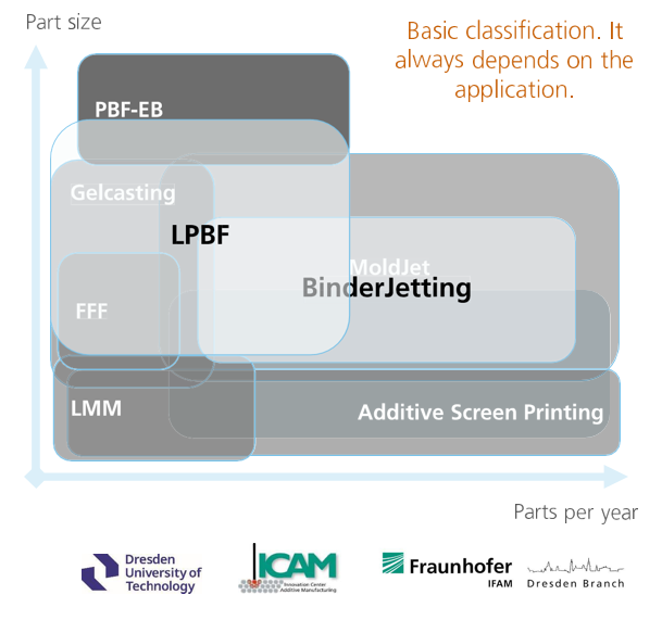
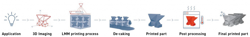
In his presentation, Thomas Weissgärber (Fraunhofer IFAM) focused on post-build processing challenges in sinter-based AM, emphasising that debinding and sintering are major determinants of final part quality and dimensional stability. Weissgärber briefly highlighted Fraunhofer IFAM’s role as a multi-site applied R&D institute, and noted the Dresden group’s focus on Powder Metallurgy and Additive Manufacturing. Fig. 2 positions sinter-based AM within a broader process landscape by mapping AM process envelopes against part size and annual production volume.
The major post-build steps were outlined (Fig. 3), with two debinding pathways distinguished. In the first route (Fig. 3, top), green parts undergo solvent debinding to remove a substantial fraction of organic binder, followed by thermal debinding and sintering in a high-temperature furnace. This two-step pathway is commonly used in MIM/CIM-derived workflows such as Filament-based Material Extrusion (MEX – also known as Fused Filament Fabrication, FFF) and Vat Photopolymerisation (VPP).
![Fig. 3 Major post-build steps, including debinding and sintering. Top: steps typically used in Metal and Ceramic Injection Moulding (MIM, CIM), Filament-based Material Extrusion (MEX, also known as Fused Filament Fabrication (FFF)) and Vat Photopolymerisation (VPP), also known as Lithography-based Metal Manufacturing (LMM). Bottom: steps typically used in MoldJet, 3D screen printing, gel casting, and metal Binder Jetting (Courtesy Thomas Weissgärber, Fraunhofer IFAM) [2]](http://www.pim-international.com/wp-content/uploads/sites/2/2026/02/fig-03-1024x786.png)
In the second route (Fig. 3, bottom), where the binder content is lower, parts can proceed directly to the furnace for one-step thermal debinding followed by sintering; this approach is typically used in processes such as MoldJet, 3D screen printing, gel casting, and metal Binder Jetting.
FTIR off-gas monitoring for debinding process control
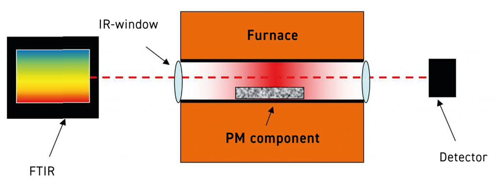
In thermal debinding studies, Weissgärber highlighted the extensive use of Fourier Transform Infrared (FTIR) off-gas analysis to probe the decomposition of organic components, carburisation/decarburisation behaviour, and the reduction of outer and inner oxides. The practical requirements were framed as complete binder removal, minimised residual carbon and oxygen, avoidance of damage (blistering, pore formation, cracking), and reduced cycle time. A laboratory FTIR setup is shown in Fig. 4, and the extension of this approach to industrial furnaces – via direct process-gas analysis in the furnace chamber – enables monitoring outputs that mirror time-temperature profiles (Fig. 5).
![Fig. 5 FTIR gas analysis for an FFF-fabricated 316L specimen in a hydrogen atmosphere at ambient pressure (Courtesy Thomas Weissgärber, Fraunhofer IFAM) [3]](http://www.pim-international.com/wp-content/uploads/sites/2/2026/02/fig-05-1024x855.png)
A 316L example (Fig. 6) demonstrated how FTIR-guided optimisation can yield non-intuitive thermal debinding steps at 410°C and 570°C, a dwell at 90-95% of peak temperature, and use of CH/CH4 signals as process indicators, with decomposition treated as complete when the signal disappears. The main decomposition-step dwell time was reported to be on the order of two hours. Additional uses discussed included predicting crack formation and accelerating the development of lower-impurity cycles, with associated time and cost savings.
![Fig. 6 FTIR-based analysis of furnace exit gas during thermal debinding and sintering of an FFF-fabricated 316L specimen using a hydrogen atmosphere at ambient pressure. Top: thermal debinding cycle derived from FTIR gas analysis (Courtesy Thomas Weissgärber, Fraunhofer IFAM) [4]](http://www.pim-international.com/wp-content/uploads/sites/2/2026/02/fig-06-942x1024.png)
Sintering modelling and distortion mechanisms
On the sintering side, the presentation emphasised the Master Sintering Curve (MSC) as a tool for predicting density evolution during sintering and supporting process optimisation to reduce energy and cost. This approach was described as relying on dilatometry at different heating rates and the calculation of time- and temperature-independent parameters; a mathematical representation is provided in Fig. 7, including a microstructural evolution term.
![Fig. 7 Mathematical framework underpinning the Master Sintering Curve, illustrating the coupling between densification kinetics, microstructural evolution, and the dominant atomic diffusion mechanism (Courtesy Thomas Weissgärber, Fraunhofer IFAM) [5]](http://www.pim-international.com/wp-content/uploads/sites/2/2026/02/fig-07-1024x489.png)
However, sintering simulation remains complicated by distortion and slumping, particularly for unsupported geometries (an example beam structure reportedly began slumping at 1,271°C), suggesting that supports may be required in some cases. Friction between parts and the sintering tray was also noted as a contributor to ‘elephant foot’ effects. More broadly, prediction becomes more difficult as geometry complexity increases, and while many models assume isotropic shrinkage, practical shrinkage is often anisotropic, further complicating shrinkage and distortion prediction.

In concluding remarks, Weissgärber noted that viscosity varies with both temperature and hold time: increasing temperature reduces viscosity, while longer holds increase it. This behaviour is not straightforward to implement in commercially available software, and the work pointed to a need for modelling concepts beyond anisotropic scaling factors. Warpage was described as sensitive to particle size distribution, green-density gradients, temperature, heating rates, and frictional interactions with sintering trays.
Solvent on granules AM for Shape Memory Alloys (SMAs): Fe-based results
An interesting presentation entitled ‘Solvent on Granules 3D Printing of Iron-based and Nickel-Titanium Shape Memory Alloys’ was delivered by Efrain Carreño-Morelli (University of Applied Sciences and Arts Western Switzerland). Carreño-Morelli first introduced the University and described his laboratory’s end-to-end capabilities across feedstock preparation, shaping, thermal processing, and characterisation.
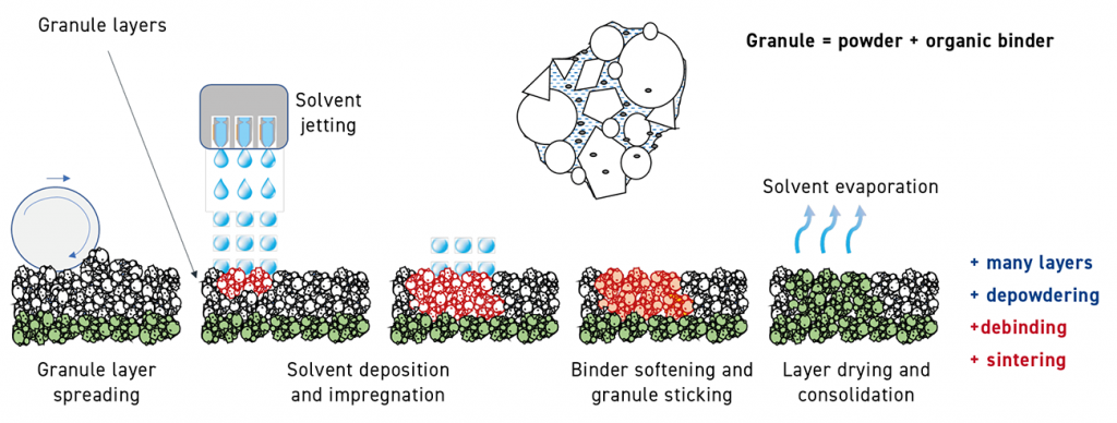
Carreño-Morelli then explained the solvent on granules Additive Manufacturing (SG-3DP, patent pending) process. The process first forms granules made from actual powders combined with a proprietary binder. During the build, these granules – rather than individual powder particles – are spread across the build bed. The solvent is then selectively jetted into the desired regions of the granule bed, and the sequence is repeated to form the green part. The binder in the granules softens, causing the granules to adhere to each other; the solvent is then removed by evaporation, followed by sintering to densify the part. A schematic of the solvent over granules AM process (patent pending) is shown in Fig. 8, and scanning electron photomicrographs of a granule are shown in Fig. 9.
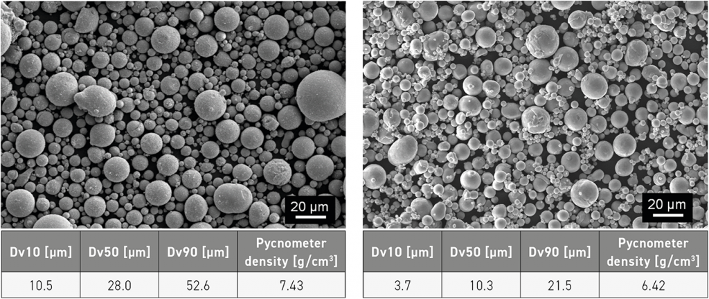
![Fig. 9 SEM photomicrographs of two granules produced from different powders (Courtesy Efrain Carreño-Morelli, University of Applied Sciences and Arts Western Switzerland) [6, 7]](http://www.pim-international.com/wp-content/uploads/sites/2/2026/02/fig-09-1024x453.png)
Using the solvent on granules approach, a range of materials and parts have been produced, including Invar Fe36Ni, porous titanium derived from titanium hydride, nickel-free stainless steel, a Fe-6.5Si-based soft ferromagnetic alloy, and some grades of hardmetals.

Why SMAs, and why Fe-based systems?
Carreño-Morelli then shifted to the presentation’s core focus: iron-based and nickel-titanium shape memory and superelastic alloys. He noted that shape memory behaviour can arise via thermally induced martensite formation and stress-induced martensite, and that both shape memory and superelastic responses depend strongly on transformation temperatures and service temperature conditions. A key mechanism in SMAs is the austenite-to-martensite transformation, shown schematically in Fig. 10.
![Fig. 10 Reversible martensite-to-austenite transformation with representative martensite and austenite microstructures. As: austenite start; Af: austenite finish; Ms: martensite start; Mf: martensite finish (Courtesy Efrain Carreño-Morelli, University of Applied Sciences and Arts Western Switzerland) [9]](http://www.pim-international.com/wp-content/uploads/sites/2/2026/02/fig-10-1024x997.png)
Some reasons for using SG-3DP for SMAs include the ability to achieve ‘classical’ Powder Metallurgy microstructures and the use of small test-powder batches (around 1 kg). The exploration of Fe-based SMAs was prompted by their lower cost relative to NiTi alloys and by the limited sinter-based AM literature in this area. Current investigations also suggest that the superplastic window can be expanded in Fe-based alloys, and that certain compositions can recover shape over a small temperature range – or even exhibit a near temperature-independent response – as reported by Xia et al [9]. Fig. 11 shows a schematic of the widening of the superplastic window for a superplastic iron-based alloy.
![Fig. 11 Schematic showing widening of the superplastic window for a superplastic iron-based alloy (Courtesy Efrain Carreño-Morelli, University of Applied Sciences and Arts Western Switzerland) [10]](http://www.pim-international.com/wp-content/uploads/sites/2/2026/02/fig-11-1024x614.png)
Results: transformation behaviour and auxetic compression response
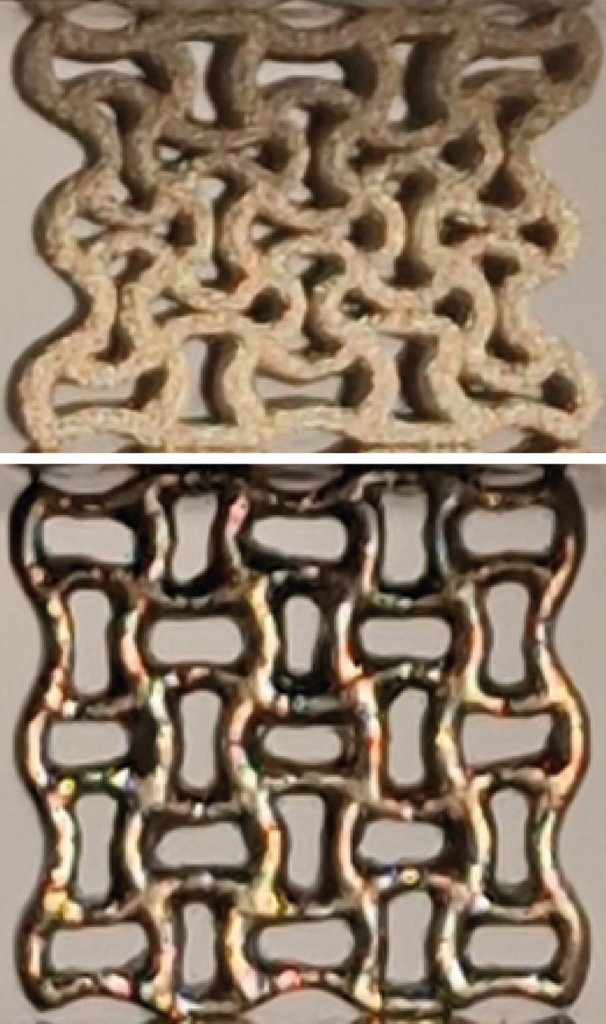
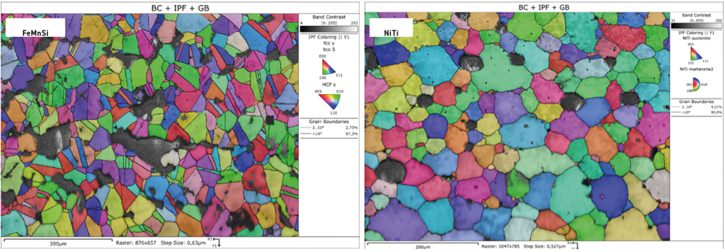
The study applied solvent on granules AM to both an FeMnSi-based alloy (Fe17Mn5Si10Cr4Ni) and a Ni-based alloy (NiTi). Fig. 12 shows SEM photomicrographs of the two powders. Auxetic structures (metamaterials with a negative Poisson’s ratio) were additively manufactured and then sintered (Fig. 13).
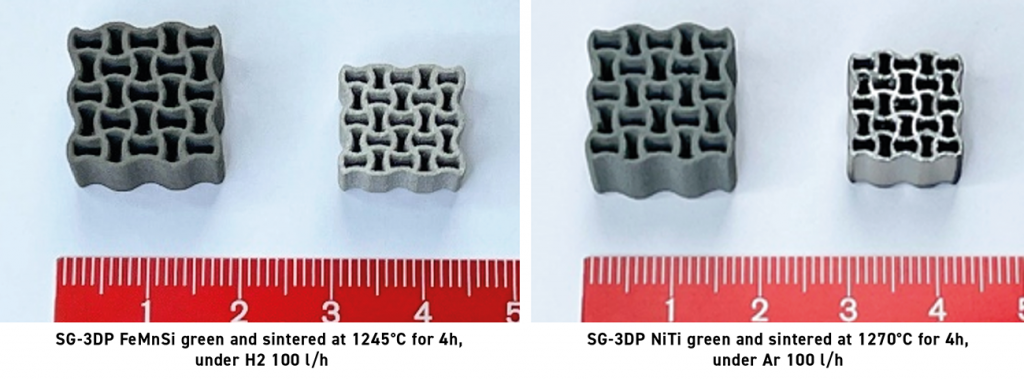
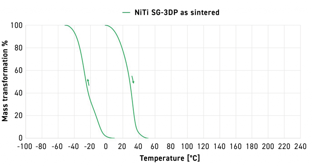
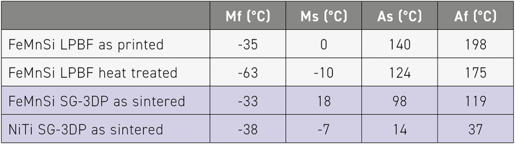
Fig. 14 shows heating and cooling mass transformation curves for FeMnSi (PBF-LB as-built, PBF-LB heat-treated, and SG-3DP as-sintered). Fig. 15 shows the corresponding curves for SG-3DP NiTi (as-sintered). The corresponding transformation temperatures (Mf, Ms, As, Af) are summarised in Table 1. Mechanical behaviour was assessed in compression on as-sintered auxetic structures at 19.8 kN (Fig. 16), with microstructural context provided by the corresponding as-sintered micrographs (Fig. 17).
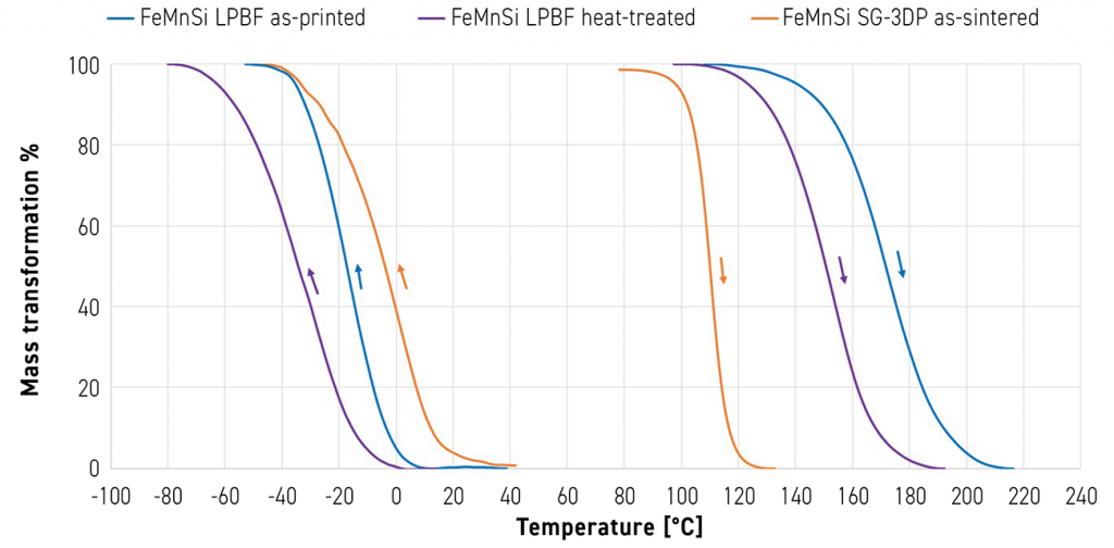
Carreño-Morelli noted that, to the best of his knowledge, these are the first reported results on Fe-based SMAs processed by sinter-based AM. The work demonstrated successful processing of Fe17Mn5Si10Cr4Ni powder via SG-3DP, debinding, and sintering. The recoverable strain is also of the order of that of the material processed by PBF-LB. Further work is in progress to characterise stress recovery and microstructure.
Materials development as an enabler for LMM
In his presentation, ‘Material Development as Enabler for the Lithography-based Metal Manufacturing (LMM) Process’, György Harakály from Incus 3D focused on the binder chemistry for the Lithography-based metal manufacturing process. Harakály stressed that material development in sinter-based AM should place greater emphasis on polymer-related research (rather than metallurgical research), since shaping is performed using various polymeric compounds across most (if not all) sinter-based AM technologies.
Harakály discussed in detail Incus’ VPP approach, highlighting several claimed advantages, including a photo-reactive, high-viscosity (‘butter-like’) feedstock, a high-quality coating mechanism, high design freedom and MIM-comparable part quality and green strength. He also emphasised practical benefits, such as easier material changeover and a powder-free working environment that does not require inert gas purging or extensive cleanup. He further highlighted part-quality outcomes reported for LMM, including high surface quality and densification, as well as the capability to fabricate intricate geometries, such as threads, undercuts, and fine as-built features. A schematic of the Incus process is shown in Fig. 18.
![Fig. 19 Three broad categories of polymeric materials used in Additive Manufacturing (Courtesy György Harakály, Incus 3D) [11]](http://www.pim-international.com/wp-content/uploads/sites/2/2026/02/fig-19-1024x335.png)
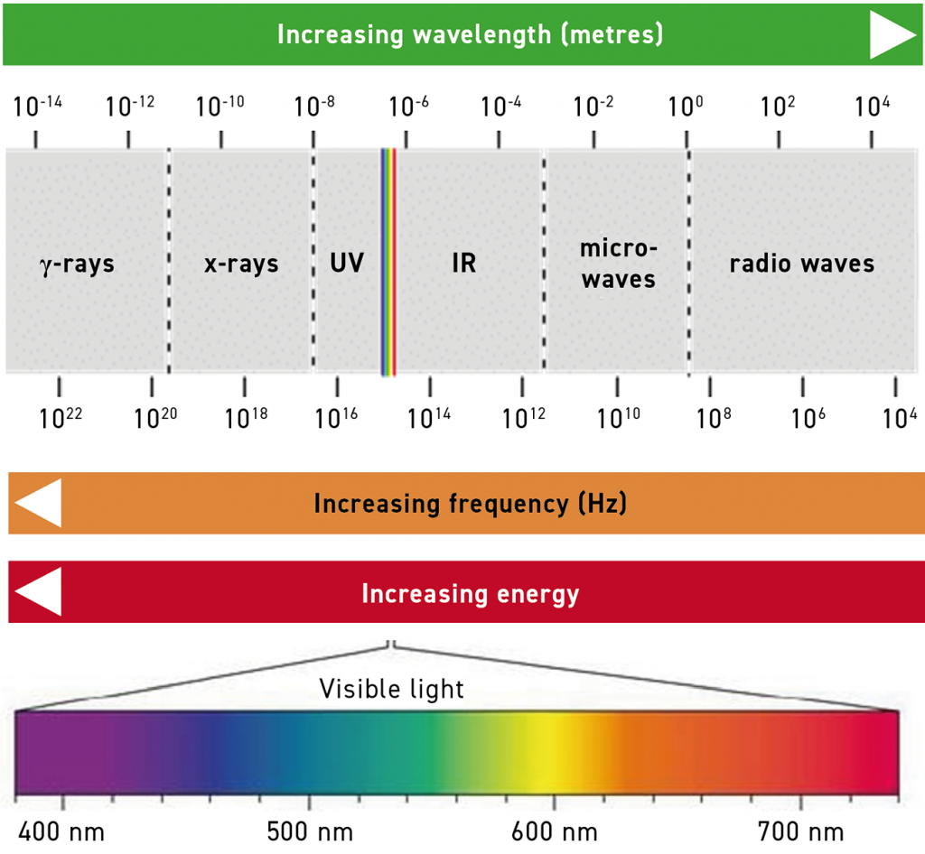
There are primarily three broad categories of polymeric materials, as shown in Fig. 19, from which LMM materials have been described as thermoset. From the LMM standpoint, light physics is also a factor. Absorption of UV-VIS light affects polymerisation efficiency in various cases, such as for materials like tungsten or gold. Fig. 20 shows the various wavelengths and frequencies.
Why LMM outcomes depend on binder chemistry
Harakály noted that various aspects of polymer physics and chemistry govern matrix development. LMM uses radical-initiated chain-growth polymerisation. To enable this, photo-initiators are used, which generate radicals by photo-fragmentation via homolytic cleavage, hydrogen abstraction, or electron transfer. This is controlled by the quantum chemistry of the molecule, as can be illustrated by a Jablonski diagram, which maps the photo-initiator’s excited-state pathways (e.g. intersystem crossing) relevant to radical formation.
Harakály also emphasised that the matrix-shaping mixture is not only based on carbon-oxygen-nitrogen-hydrogen, but that each shaping technology may incorporate various heteroatom-containing compounds (such as flow-controlling agents, photo-initiators, or even the base resin itself). Thus, controlling the chemistry for shaping is imperative, as these factors will ultimately appear as contaminants in final products. In some cases this is detrimental: for example, phosphorus contamination in tungsten alloy systems, or contaminants that affect copper conductivity.
Radical-initiated chain growth polymerisation drives covalent bonding of chemical compounds, in contrast to the predominantly physical binder cohesion typical of many MIM systems. This leads to polymerisation shrinkage, which needs to be controlled during the shaping process. Polymer degradation is also an important factor for the overall process. This is mainly governed by the chemical structure of the components used, the physical structure of the resulting polymer network and various other factors.
What is known in the industry as ‘post-debinding graphite’ is likely not graphite, but rather polycyclic aromatic hydrocarbon (PAH) derivatives, as reported in polymer degradation literature. Given the importance of carbon control in achieving desired final properties in numerous metal alloys, he argued that optimal outcomes depend not only on the development of appropriate debinding parameters but also on selecting a suitable polymer composition.
Finally, Harakály noted that metal-polymer interactions can introduce additional complexity during material development: unwanted reactions may occur due to metal catalysis and the chemical activity of alloying elements. His overarching message was that close collaboration between chemists and metallurgists is essential to advancing sinter-based AM.
LMM for medical applications
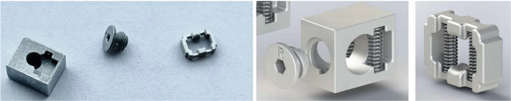
Mattia Forigiarini (Azoth) discussed LMM for medical applications, presenting it as a sinter-based AM route suited to small, complex components where fine features, surface finish, and repeatability are critical. He outlined case studies of electromedical connectors and an articulated joint for a needle driver.
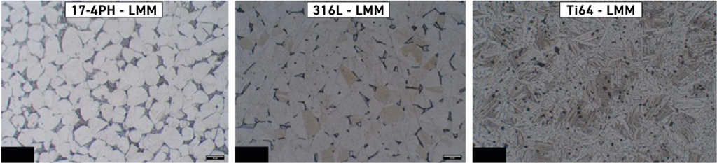
Azoth positions itself as a high-volume manufacturer of small metal parts using multiple sinter-based AM process platforms (including LMM), with application engineering intended to support progression from prototype builds to production on the same equipment. For medical work, Azoth cited ISO 9001 and ISO 13485:2016 certification. Common medical materials discussed included 17-4 PH, 316L, and Ti-6Al-4V; Fig. 21 shows representative microstructures. Azoth reported densities >99% without post-sinter HIP. Ti-6Al-4V Grade 5 was described as under active development.
Electromedical connectors
In the electromedical connector assembly (Fig. 22), the set-screw is 2.4 mm long and features fine threads (pitch ~0.4 mm). The connector also requires spring-pin positional tolerances of ±0.02 mm and an as-built surface finish of ~2.5 μm Ra. The part incorporates recessed features and tight assembly interfaces that would be challenging to manufacture conventionally without complex tooling or multi-part assembly. These connectors are part of a device designed to treat memory-degenerative diseases such as Alzheimer’s (informally described as a ‘plug-in extended memory’ for the brain). The part is currently in advanced animal testing.
LMM was selected to support testing and qualification that require thousands of parts and multiple design iterations, while maintaining a consistent route from prototype to production without additional tooling or requalification at each design change – reducing iteration time and tooling costs.
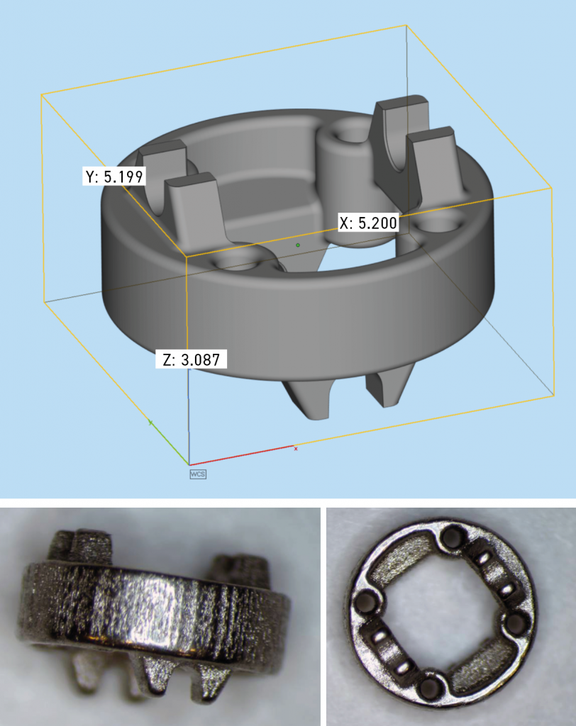
Needle-driver articulated joint
The second case study focused on an articulated joint for a minimally invasive manual needle driver (Fig. 23), designed as part of a gimbal mechanism to improve surgeon ergonomics while maintaining controlled needle motion. The part diameter is 5.2 mm and includes 0.46 mm holes, with multiple features requiring tolerances within ±0.075 mm. The as-built surface requires a smooth finish to prevent wear and abrasion during movement. Forgiarini highlighted LMM’s ability to meet feature-resolution and strength requirements in 17-4 PH stainless steel (with H900 heat treatment) while also meeting wear-sensitive surface requirements.
In closing, Forgiarini argued that LMM can relax design constraints for small medical components, enabling fine features and smooth surfaces with good dimensional accuracy, and improving cost-effectiveness as throughput increases. He positioned the process as sufficiently mature and controllable to support higher-volume manufacture with shorter lead times than conventional routes for selected part families.
Processing P91 heat-resistant steel by Binder Jetting for energy applications
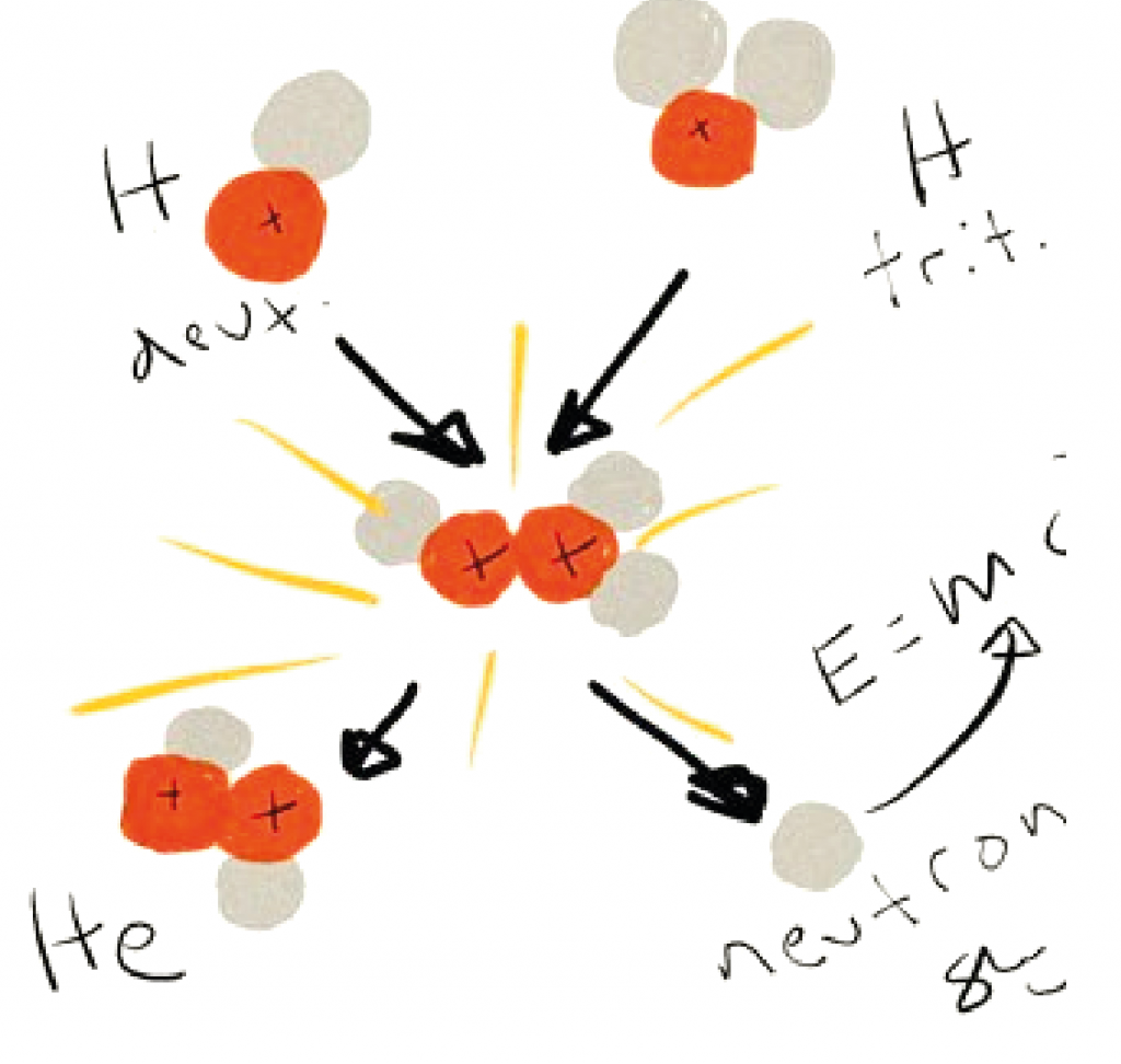
Iñigo Agote (Tecnalia, Basque Research and Technology Alliance, Spain) presented work on processing P91 heat-resistant steel by Binder Jetting for energy applications, with a particular focus on fusion-relevant reduced-activation ferritic-martensitic (RAFM) steel systems. Agote introduced Tecnalia as Spain’s largest applied research and technological development centre and a British Research and Technology Association (BRTA) member, noting its scale (around 1,520 staff) and international workforce. To frame the application space, he provided a brief fusion overview (Fig. 24), describing plasma confinement of hydrogen isotopes at temperatures above 100,000,000°C to enable helium formation and energy release.
Agote cited fusion-related constraints highlighted by the Culham Centre for Fusion Energy (CCFE), beginning with the need for reduced-activation structural alloys that are not readily activated under neutron irradiation (e.g. RAFM steels). He also noted requirements associated with complex cooling architectures, multimaterial systems, high-temperature and erosion resistance, and advanced joining technologies.
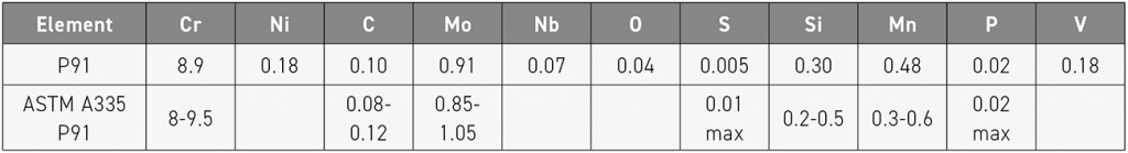
Within this context, the work explored the processability of RAFM steels by Binder Jetting, focusing on P91 (9Cr-1Mo) and Eurofer97 (9Cr-1W-0.15Ta). P91 is a martensitic 9 wt.% Cr–1 wt.% Mo alloy used where creep resistance and high-temperature capability are required, including high-temperature steam piping, boiler components, and steam manifolds. Agote positioned the study as an initial feasibility assessment of Binder Jetting P91 to support increasingly complex component designs for next-generation energy systems.
Feedstock characterisation and build window
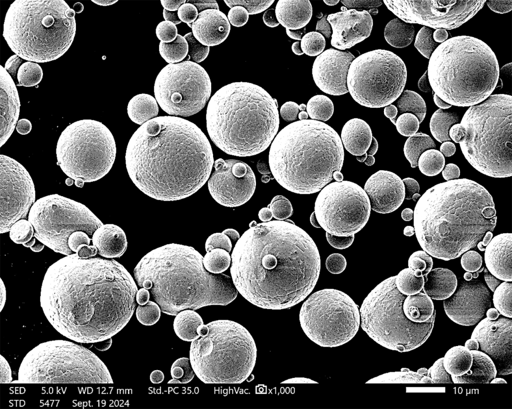
The P91 feedstock was an atomised powder produced specifically for Binder Jetting by Hoeganaes USA (GKN Powder Metallurgy) (Fig. 25), with D10 ~ 9.1 µm, D50 ~ 10 µm, and D90 ~ 33 µm. The powder chemistry (Table 2) falls within the alloy specification range.
Agote then related feedstock characteristics to BJT processability: the powder exhibited a wide particle size distribution with a notable fine fraction, which may benefit packing; particle morphology was primarily spherical with some elongated particles. Tap and apparent density measurements (as-received and after drying) indicated good packing behaviour and a high powder-bed density. The calculated Hausner ratio indicated good flowability for recoating and spreading, while the cohesive index ranked the powder as fair to passable, indicating adequacy for BJT. The overall process flow is outlined in Fig. 26.
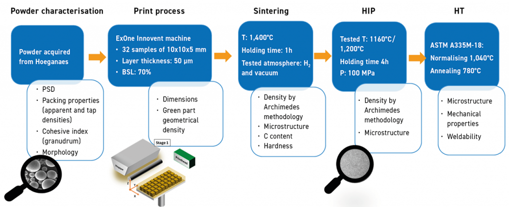
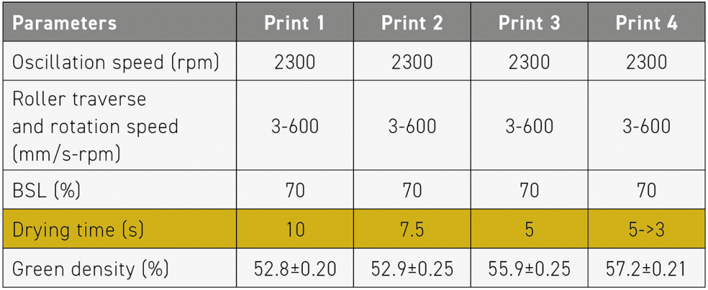
Parts were built on an ExOne machine, and the results showed drying time to be a sensitive parameter: reducing it from 10 s to 3 s improved part quality and increased green density to 57.2% (Table 3), with deviations from stereolithography (STL) of 2.4% in X/Y and 3% in Z.
Debinding, sintering, HIP, heat treatment, and properties
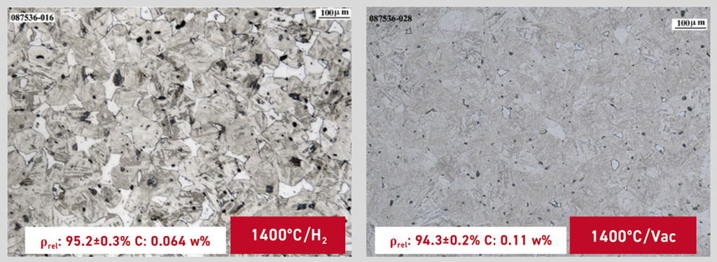
Debinding was performed under argon at 475°C, following the ExOne Aquafuse binder procedure. Relative density after sintering was above 94%, but the atmosphere selection strongly influenced both the chemistry and the microstructure. Under hydrogen, carbon loss promoted higher ferrite content, whereas vacuum sintering provided a better balance between density, carbon level, and microstructural integrity (Fig. 27).
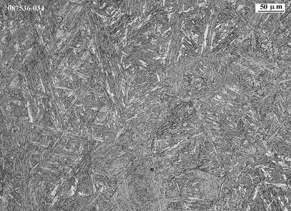
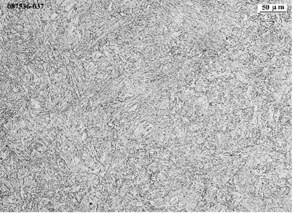
Post-sinter HIP at 1,200°C for 4 h at 100 MPa increased relative density to >99%; hardness was 426 ± 3 HV, and the microstructure was almost fully martensitic with larger needle features (Fig. 28). To match commercially supplied material conditions for mechanical testing, HIPed parts were then normalised and annealed in accordance with ASTM A335M-18 (normalising at 1,040°C, followed by annealing at 780°C), producing a finer microstructure than the as-HIPed condition (Fig. 29).
Following coupon trials, tensile specimens were manufactured to ASTM E-8 via BJT and subjected to the same heat-treatment route prior to testing. Agote reported that BJT for P91 fulfils ASTM A213-T91 requirements (for 9Cr-1Mo steels used in high-temperature, high-pressure steam service) (Table 4). Ongoing work includes assessment of weldability. The presentation closed with a complex high-pressure manifold demonstrator fabricated via BJT (Fig. 30).
Binder Jetting in high-volume production: advances and challenges
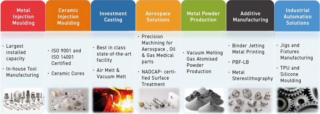
Mukund Nagaraj (Indo-MIM, San Antonio, Texas) presented ‘Binder Jet Metal Printing in Mass Production – Advances and Challenges,’ focusing on what it takes to run BJT as a production process rather than a prototyping tool. He opened by positioning Indo-MIM’s broader manufacturing base – spanning MIM, CIM, investment casting, aerospace solutions, metal powder production, AM, and industrial automation (Fig. 31).
Nagaraj linked growth in production AM to larger machine fleets and industrially driven application development, including material validation with OEMs, research labs and universities. He emphasised early functional validation at the prototype stage, followed by scaling through automation and safety, supported by robust equipment capable of repeatable build heights up to 140 mm.
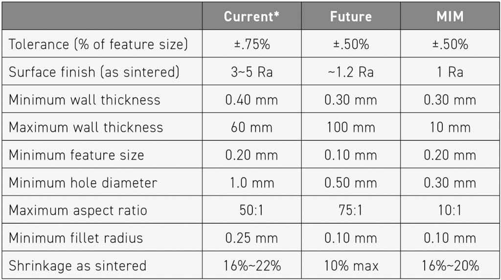
Dimensional capability was attributed to powder control and continuous recycling, with current dimensional accuracy cited at ±0.75% (or tighter), and an expanding materials portfolio that includes superalloys, tool steels, and stainless steels. Nagaraj presented densification and properties as comparable to MIM, citing ≥98% relative density in the as-sintered condition and >99.5% with HIP, and highlighted throughput of up to ~100,000 parts per year per machine. Table 5 compares current and future Binder Jetting capability alongside current MIM capability, while Fig. 32 shows an SS304 microstructure under development with twin boundaries and near-full density.
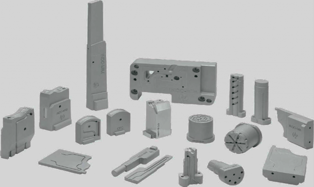
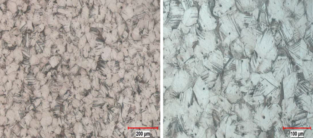
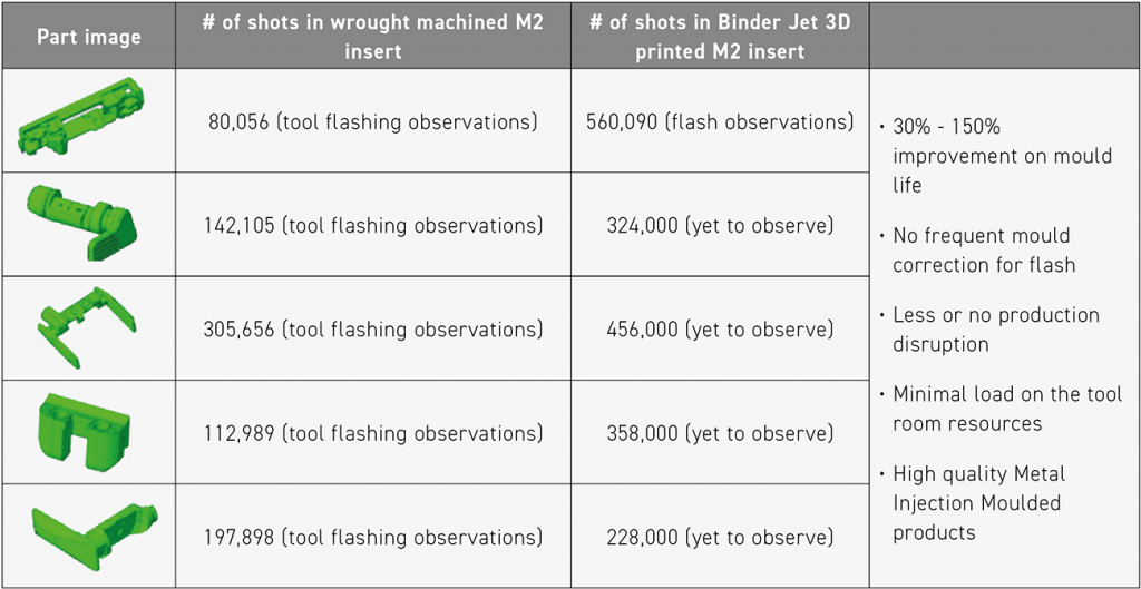
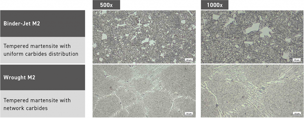
As an application example, Nagaraj discussed Binder Jetting of M2 tool steel, showing a range of complex parts (Fig. 33) and comparing insert performance against wrought-machined equivalents (Table 6). He reported mould-life improvements of 30-150%, alongside reduced need for flash-related correction and lower demand on tool-room resources. Microstructural comparison indicated tempered martensite in both BJT and wrought conditions, with a more uniform carbide distribution reported in the Binder Jet condition versus network carbides at grain boundaries in the wrought condition (Fig. 34).
Production metrics and bottlenecks
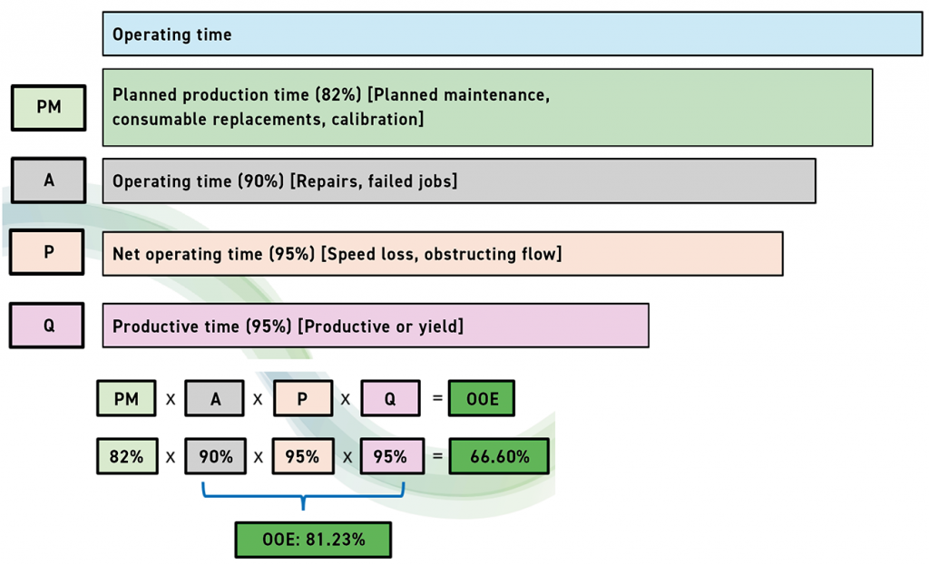
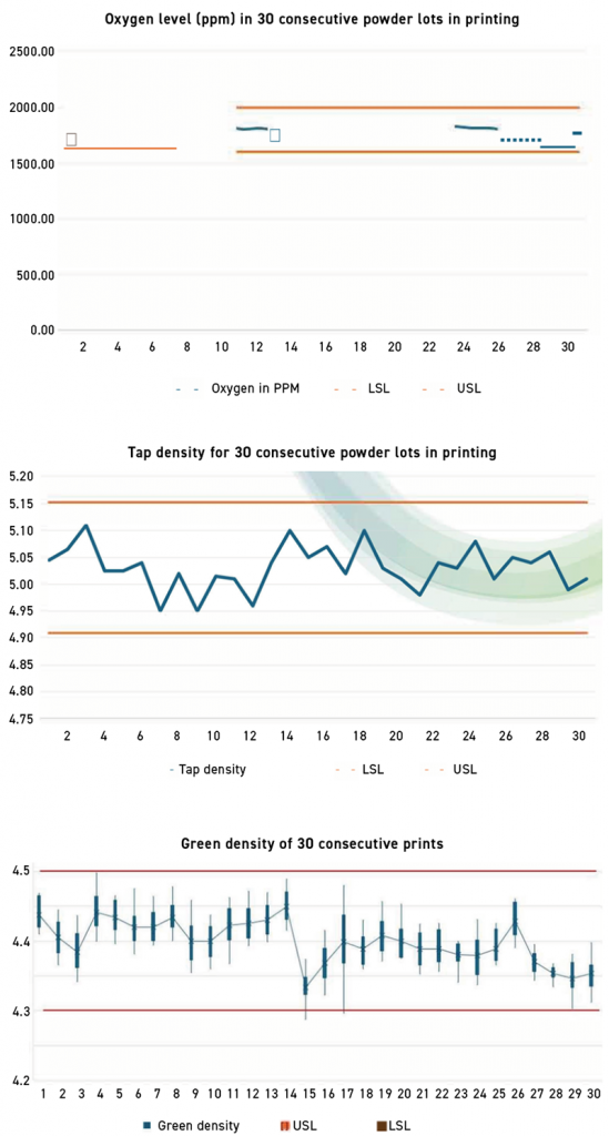
Process efficiency was discussed using Overall Equipment Efficiency (OEE) and Overall Operations Efficiency (OOE), incorporating planned production time, operating time, net operating time, and productive time (Fig. 35). Based on an average of ~8.31 jobs per machine per week and a 95% sintered-part yield, Nagaraj calculated an OEE of 81.23% and an OOE of 66.60%. Examples of production monitoring – raw material indicators (oxygen level and tap density) and green density across thirty consecutive builds – are shown in Fig. 36.
Nagaraj concluded by identifying depowdering as a critical production bottleneck and arguing for customised automation to maximise yield. He reported that depowdering time per part scales with surface area, making geometry-driven depowdering time a practical operational constraint that must be managed as part of high-volume process control.
Sinter-based AM of 316L stainless steel: tailoring microstructures and properties
Mahmood Shirooyeh (Senior Materials Scientist, 3DEO, Inc.) presented a benchmark-driven look at sinter-based AM of 316L stainless steel, positioning it as a practical workhorse for applications requiring corrosion resistance, ductility, and biocompatibility. The talk focused on establishing repeatable material performance relative to established sinter-based routes such as Metal Injection Moulding.
The study outlines 3DEO’s Intelligent Layering process, in which metal powder is spread in thin layers, an aqueous binder is applied, and CNC micro-end-milling is used during the build to define geometry. For the 316L study, nitrogen gas-atomised powder was used, and test artefacts were produced across multiple builds to enable statistical comparison. The experimental plan relied on standard test geometries – such as density coupons, transverse rupture strength coupons, and ASTM E8 tensile specimens – to evaluate properties including densification, pore characteristics (morphology and distribution), mechanical properties, directional dependencies, and the effectiveness of HIP.
Post-processing involves curing in air, followed by depowdering, debinding, and sintering in a partial hydrogen atmosphere. Thermal profiles for these steps are optimised using data derived from TGA/DSC and dilatometry.
Benchmark results: as-sintered vs HIP
In the baseline condition, densification was reported at ~98.2% relative density. Post-sinter HIP increased the density to ~99.5%. Image-based porosity analysis revealed fine, dispersed pores in the as-sintered condition, with an area fraction of ~1.8%, whereas HIP eliminated the overwhelming majority of detectable pores (down to ~0.04-0.05% area fraction).
Mechanical testing reported a yield strength of ~180 MPa, ultimate tensile strength of ~530 MPa, and ductility of ~60% in the as-sintered state. Post-sinter HIP primarily resulted in further ductility gains (to ~80%) and largely removed any elongation anisotropy, while slightly reducing hardness, consistent with grain coarsening. The surface roughness (Ra ~3.8-3.9 µm) was essentially unchanged by HIP, while the magnetic permeability approached ~1 (more non-magnetic), aligning with expectations for 316L and its typical application requirements.
Sintering of Cold Spray AM products: EPIC as a PM-style route
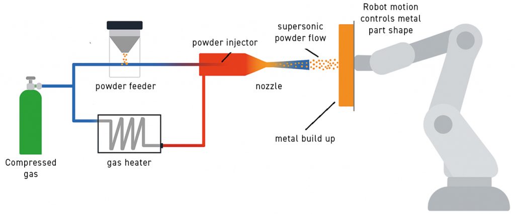
Animesh Bose (Shaping Innovations, LLC, USA) presented ‘Sintering of Cold Spray Additive Manufacturing Products,’ based on work led by Spee3D (co-authored by Steven Camilleri, Andrew Duguid, and Tien Tran, Spee3D, Darwin, Australia; and Krishnan Kannoorpati, Charles Darwin University, Darwin, Australia). While Cold Spray is widely used for coatings and repair, the talk highlighted its use as a freeform shaping step for near-net-shape parts, followed by sintering and/or HIP to develop alloy homogeneity and target properties.
Bose briefly introduced Shaping Innovations (primarily involved in global Powder Metallurgy consulting) and Spee3D, a provider of metal AM technology based on the Cold Spray process. Spee3D’s current materials portfolio includes aluminium 6061, aluminium bronze, copper and stainless steel, with additional materials in development. Bose positioned Spee3D’s Cold Spray AM as a rapid, solid-state route in which powder is deposited at supersonic velocity and bonds by high-velocity impact without melting (Figs. 37-38), producing dense, freestanding green compacts that can be post-processed by sintering and/or HIP to achieve target properties.
EPIC process: shaping by Cold Spray, densification by heat
Bose then discussed Spee3D’s Extreme Particle Impact Consolidation (EPIC) process. In EPIC, Cold Spray is used to generate the near-net shape, followed by sintering and/or HIP to develop alloy homogeneity and target properties. The cold sprayed deposits form dense, freestanding green compacts, and EPIC was presented as a press-free PM-style route for forming billets from pure Cu and blended elemental nickel–aluminium bronze (NAB) systems.
Bose emphasised that EPIC follows the conventional PM logic path (powder → compact → sinter/HIP → finishing) but replaces die pressing with motion-controlled Cold Spray deposition. Unlike conventional Cold Spray (typically repair-/coating- oriented), EPIC assumes thermal post-processing; in many cases, the heat-treatment stage is framed less as bulk densification and more as diffusion-driven homogenisation and microstructural development, since cold sprayed structures can already be ~98% dense.
Results: copper handling strength and NAB homogenisation
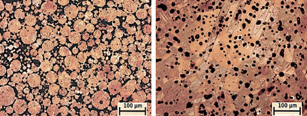
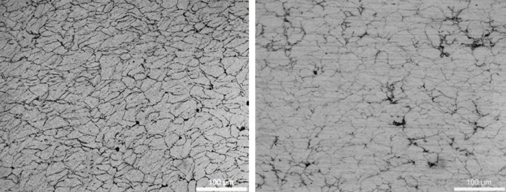
EPIC copper exhibited near-full density in the as-sprayed state with green strength >100 MPa, enabling handling and machining in the green state (Fig. 40, as-sprayed vs 200°C heat-treated). No shrinkage data were generated in this study, but porosity was already low in the as-sprayed condition; EPIC heat-treated parts exhibited good recrystallisation and sintering behaviour even at 200°C. For comparison, conventional PM copper after 610°C and 1,020°C heat treatment is shown in Fig. 39.
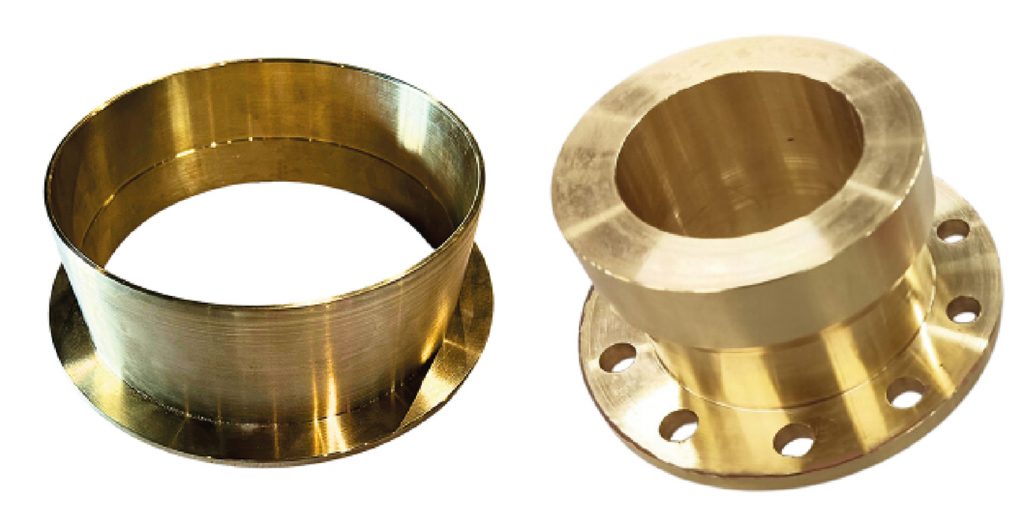
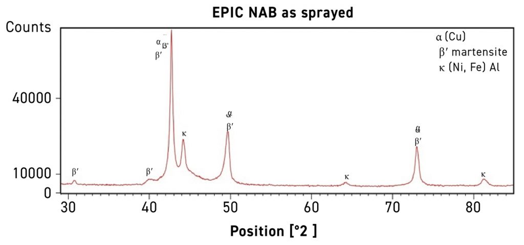
NAB is a key naval alloy, but supply is increasingly constrained by availability of skilled staff. Conventional PM processing is difficult due to poor sintering behaviour, elemental segregation, and Kirkendall porosity. EPIC overcomes these challenges by cold-spraying blended elemental powders and applying liquid-phase sintering. Cu (~80%), Al (~10%), Fe (~5%), and Ni (~5%) powders were cold sprayed into a billet and then thermally processed to form NAB while retaining part geometry. Fig. 41 shows homogenisation after sintering; Fig. 42 shows two near-net-shape NAB parts produced via EPIC-fabricated NAB parts.
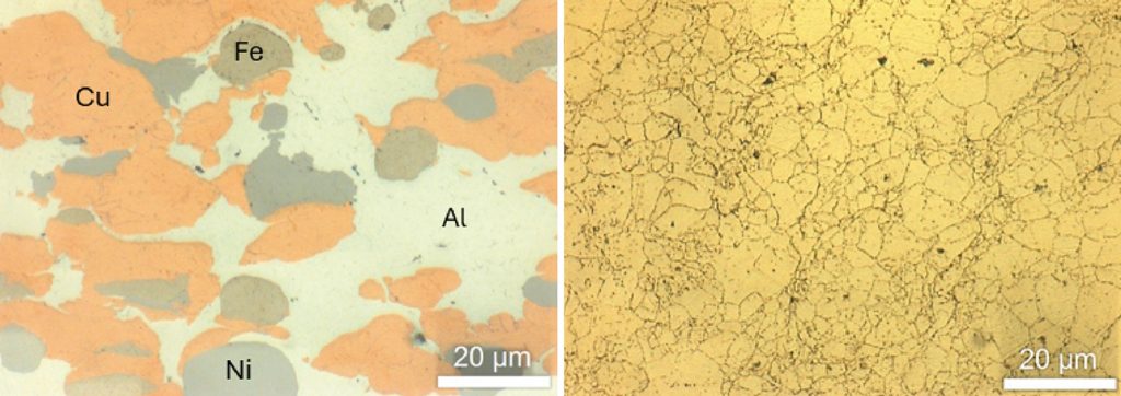
omogenisation was further supported by XRD (Fig. 43), which showed fully developed α (Cu-rich), β′ (martensitic), and κ (Ni-Fe-Al) phases, with no residual elemental peaks, consistent with complete alloying.
In some cases, parts were subjected to post-sinter HIP; containerless HIP was carried out at 950°C, 100 MPa for 5 h. Bose reported that the mechanical properties of EPIC-processed NAB exceeded C63000 wrought NAB specifications, supporting the claim that EPIC can create structural-grade alloys from blended elemental powders.
In conclusion, EPIC requires no dies or mechanical pressing, and billets can be shaped using motion-controlled Cold Spray paths. Large parts are more achievable, and the scales are unusual for conventional PM. This raises an interesting question: Is EPIC an AM way of doing PM? EPIC does not use mechanical compaction; instead, it forms a powder compact that requires thermal post-processing (sintering and/or sinter/HIP). The material behaviour mirrors PM in bonding and phase development, and many traditional PM techniques apply (except pressing). It can also be used in an AM sense – complex geometries, in-field production, and no tooling. Cold Spray followed by sintering or HIP should be considered a powder consolidation method. It does not displace press-and-sinter, but adds an alternative shaping process with distinct advantages.
Cold Metal Fusion: achieving smooth surfaces efficiently with green part processing
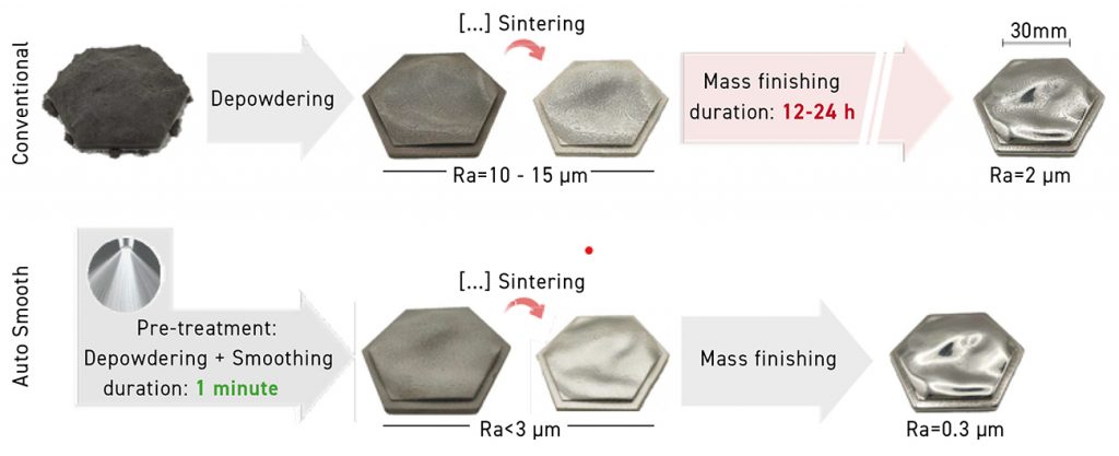
Marcel Strobel (Headmade Materials, Germany) presented Cold Metal Fusion (CMF), a sinter-based route combining an SLS-style laser-sintering step to form green parts, followed by solvent debinding, sintering and post-processing. He argued that CMF’s high green-part strength reduces the number of parts damaged between AM processing and the furnace, lowering scrap rates and, in turn, the cost per part. The same green robustness enabled a wide range of green-state secondary operations (including smoothing, tapping, milling, and blasting), especially valuable for alloys and geometries that are difficult to machine after sintering. Strobel also described automation potential across the process chain (from unloading and depowdering to robot-assisted surface treatment), including part- or geometry-specific automated routines. High green strength was further linked to the survivability of fine features and to more aggressive cleaning/finishing steps, including reported water-jet cleaning at ~30 bar on parts with ~1 mm wall thickness.
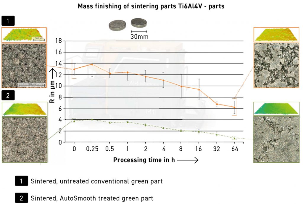
A recurring theme was surface quality: CMF’s green-state AutoSmooth step was shown (Figs. 44–45) to improve downstream mass-finishing effectiveness relative to conventional green-part routes. Figs. 46-47 show green parts undergoing blasting and highlight broad CMF application areas. Current CMF materials reported include 316L, 17-4 PH, Ti-6Al-4V, M2, and Inconel 625, with TiAl4822 and H13 under beta evaluation. Two pump components – housing and impeller – were used as application examples, including functionally integrated cooling in the housing. For impellers (Fig. 48), Strobel cited potential efficiency gains (claimed ~2–5%) from improved and more uniform surface quality, with end-customer ROI driven by electricity savings. Finally, a benchmark study by Institut Carnot/CETIM (France) was referenced, reporting strong mechanical properties for CMF 316L compared with other technologies, alongside suitability for larger geometries (impellers >250 mm in diameter) and higher production volumes.
Conclusion
This selection of presentations from ASTM ICAM 2025, focused on the Value Chain track ‘Sinter-based AM technology’, reflects the author’s judgement of the most relevant contributions for a Powder Metallurgy readership; many additional presentations of interest could not be included due to space constraints. More broadly, ASTM ICAM remains substantially larger than any single track, and the technical breadth of the meeting is best appreciated in person.
Within sinter-based AM, Binder Jetting remains a major platform, but several speakers indirectly reinforced that it is facing increasing competitive pressure. A growing number of alternative sinter-based routes are maturing and beginning to address applications that have historically aligned with Binder Jetting – particularly at the two extremes of part scale (larger components and very small precision parts). The SBAM track at ASTM ICAM continues to provide a useful cross-section of both these newer process families and developments in more established platforms, alongside continuing growth in materials and application readiness.
The Sinter-based AM Technologies (SBAM) track at ASTM ICAM 2025 was organised by Animesh Bose (Shaping Innovations, LLC, USA), Efrain Carreño-Morelli (University of Applied Sciences and Arts Western Switzerland, HES-SO, Switzerland), Amy Elliott (Oak Ridge National Laboratory, ORNL, USA), Simon Hoeges (GKN Additive, Germany), Benoit Verquin (CETIM, France), and Thomas Weissgärber (Fraunhofer IFAM, Germany; TU Dresden, Germany).
ASTM ICAM 2026 will take place in Orlando, Florida, where the technical programme and exhibition will provide a focused view of current qualification, materials, and scale-up priorities.
Author
Dr Animesh Bose
CEO
Shaping Innovations, LLC
Saint Cloud, FL, USA
[email protected]
References
[1] Bose, A. (2025) ‘Sinter-based Additive Manufacturing technologies in focus at ASTM’s ICAM 2024 conference’, PIM International, 19(1) (Spring 2025), 25 February. Available at: pim-international.com/articles/sinter-based-additive-manufacturing-technologies-in-focus-at-astms-icam-2024-conference
[2] Adapted from Klocke, F. (2018) Pulverspritzguss, in Fertigungsverfahren 5 (VDI-Buch). Springer Vieweg, pp. 113-124
[3] Quadbeck, P. et al (2018) Proceedings Euro PM 2018, Bilbao, Spain. ISBN 978-1-899072-50-7
[4] Strauss, A.et al (2022), HTM Journal of Heat Treatment and Materials, 77, pp. 437-448
[5] Adapted from Hansen, J. D. et al (1992), Journal of the American Ceramic Society, 75(5), pp. 1129-1135
[6] Carreño-Morelli, E. et al (2016) ‘Additive Manufacturing by Solvent Jetting on Granule Beds’, in Proceedings of World PM 2016, Hamburg, Germany. ISBN: 978-1-899072-48-4
[7] Carreño-Morelli, E. et al (2020), International Journal of Refractory Metals & Hard Materials, 92, 105276
[8] Duerig, T. (2010), ‘Shape Memory and Superelastic Technologies 2010’ (SMST) Nitinol Workshop, Monterey, CA, 16 May.
[9] Xia, J. et al (2020) ‘Iron-based superelastic alloys with near-constant critical stress temperature dependence’, Science, 369(6505), pp. 855-858. doi:10.1126/science.abc1590
[10] La Roca, A. and Sade, M. (2020) Science, 369, p. 773
[11] Dorfinger, P. (2016) Toughening of photopolymers for lithography-based 3D printing. TU Wien