Sinter-based Additive Manufacturing technologies in focus at ASTM’s ICAM 2024 conference
Sinter-based Additive Manufacturing has gained significant traction within ASTM’s International Conference on Advanced Manufacturing (ICAM), growing from a niche topic to a major area of discussion. Since its introduction as a dedicated track in 2022, interest in sinter-based AM has expanded rapidly, covering technologies such as Binder Jetting (BJT), Material Extrusion (MEX), Vat Photopolymerisation (VPP), Cold Metal Fusion, and emerging hybrid approaches. In this article, Dr Animesh Bose highlights key presentations and insights from ICAM 2024 that are shaping the future of sinter-based AM. [First published in PIM International Vol. 19 No. 1, Spring 2025 | 45 minute read | View on Issuu | Download PDF]

The evolution of ASTM’s International Conference on Additive Manufacturing
ASTM launched its largest scientific conference in 2016, creating a platform for the exchange of ideas and the transition of research into practical applications. The conference was designed to address the industry’s need for standards, design principles, and the challenges of qualification and certification. The initiative was spearheaded by two young ASTM member volunteers – Nima Shamsaei (E08 and F42 Committee member, now a professor at Auburn University) and Mohsen Seifi (also an E08 and F42 Committee member, now ASTM’s Vice President).
The inaugural event took place in May 2016 as a workshop in San Antonio, Texas, sponsored by ASTM Committee E08 on Fatigue and Fracture. Encouraged by its success, the second event followed in November 2017 in Atlanta, Georgia, co-sponsored by both the E08 Committee and the F42 Committee on Additive Manufacturing Technologies. The conference continued to expand, with the third event in November 2018, held in Washington, DC, supported by the F42 and E08 Committees as well as the E07 Committee on Nondestructive Testing. This milestone year also marked the establishment of the ASTM International Additive Manufacturing Center of Excellence (AM CoE).
Building on this momentum, the fourth event (2019) was again held in the Washington, DC, area. In response to the global pandemic, the fifth event, ASTM ICAM 2020, transitioned to a virtual format, taking place from November 16-20, 2020. Despite the challenges, the enthusiasm for the conference remained strong.
The sixth event (2021), hosted by ASTM International’s AM CoE, was held in person from November 1-5, 2021, in Anaheim, CA. Even under the lingering effects of the pandemic, the conference demonstrated remarkable resilience and continued to grow in significance.
The seventh event, ASTM ICAM 2022, took place from October 31 – November 4, 2022, in Orlando, FL, once again sponsored by the ASTM AM CoE. By 2023 and 2024, the conference had fully recovered, drawing over 1,000 attendees, reaffirming its status as a premier global forum for Additive Manufacturing. With a renewed focus on transitioning research to real-world applications through standardisation, the conference attracted experts from around the world to exchange the latest advancements in the field.

The 2021 edition of ICAM also saw the introduction of a groundbreaking new track: ‘Sinter-Based AM Technologies.’ This initiative was encouraged by ASTM Staff, Richard Huff, and brought to life by a dedicated team of four experts representing different regions:
- Usama Attia (UK)
- Animesh Bose (USA)
- Amy Elliot (USA)
- Benoit Verquin (France)
With the combined network of the co-organisers and strong support from ASTM, the first-ever sinter-based AM track featured a one-day session with fifteen technical papers, including eight invited speakers. This truly international effort underscored ASTM’s commitment to fostering innovation and expanding the breadth of topics covered at ICAM.
As ASTM’s International Conference on Additive Manufacturing continues to grow, it remains a cornerstone event for advancing the field, uniting researchers, industry leaders, and standards developers to push the boundaries of Additive Manufacturing.
A name change reflects a new manufacturing outlook
Interestingly, in 2024, the conference title was changed from ASTM International Conference on Additive Manufacturing to ASTM International Conference on Advanced Manufacturing (ASTM ICAM 2024) to broaden its scope and emphasise the importance of manufacturing generally. As ASTM’s ninth annual flagship event, ICAM 2024 focused on standardisation, qualification, and certification, addressing industry-specific requirements across the entire advanced manufacturing process and value chain.
The comprehensive agenda of this conference included over twenty symposia that covered vital topics and key areas in additive and advanced manufacturing. ICAM 2024 was organised by a dedicated team of over 100 scientific committee members, all recognised as advanced manufacturing experts hailing from sectors including industry, academia, government and regulatory agencies, national labs, and more. The sinter-based AM technologies track was classified under the value chain section of the conference, reflecting its growing importance in the industry.

The value of a sinter-based AM focus
In sinter-based AM processes, part geometry is created separately, followed by densification and property development in a separate step, which is a different approach from most other AM processes. The track abstract highlighted this distinction, emphasising that sinter-based AM processes offer several advantages over fusion-based AM, including improved resolution, superior surface finish, a wider selection of materials, and faster build speeds. These benefits reduce production costs and open up new application opportunities.
Sinter-based AM includes several technologies, as defined in ISO/ASTM 52900: Binder Jetting (BJT), Material Extrusion (MEX), Material Jetting (MJT), and Vat Photopolymerisation (VPP). Furthermore, several emerging sinter-based AM technologies are gaining attention, such as hybrid processes that combine both additive and subtractive techniques, metal Screen Printing, and multi-material Additive Manufacturing.
A unique feature of sinter-based processes is that the powder feedstock is selectively bound together with a binding agent during the build process, forming what is commonly known as a ‘green’ part. Secondary debinding and sintering steps are then required to remove the binding agent and consolidate the powder material to the desired final part density.
As one presentation explained, “While the potential of these new technologies is high, there are still challenges to address in order to achieve the economy and scale these technologies promise. Standardisation is needed to reach a positive inflection point in industry adoption.”
As stated, the conference track has grown significantly to a point where it would not be possible to cover the scope within this article. It was a challenge to pick and choose which presentations to cover here. Numerous presentations that were interesting and valuable could not be covered due to space restrictions. However, this article will focus on a select few that made a significant impact on the conference.
Binder Jetting: simulation and processing
Binder Jetting, which has gained significant traction over the past five years and is currently in widespread commercial use, naturally gained significant attention within the sinter-based AM conference track. Approximately half of the presentations were connected to Binder Jetting.
Modelling and experimental validation
The growing significance of Binder Jetting within sinter-based AM is further highlighted by several papers focusing on modelling as well as experimental validation. One notable presentation, titled ‘An Experimentally-Validated Multiphysics, Fluid-Particle Interaction Modelling Framework for Binder Jet 3D Printing’, was delivered by C Fred Higgs III from Rice University.
According to Higgs, Binder Jetting, when compared to other AM processes such as Laser Beam Powder Bed Fusion (PBF-LB), offers advantages such as faster build rates, lower costs, and a broader selection of materials. However, despite these advantages, BJT parts generally exhibit inferior mechanical properties, dimensional accuracy, and repeatability – factors that limit the technology’s adoption in high-performance sectors such as aerospace and defence. According to the presentation, developments in this area are primarily dependent on experimental approaches, which limit the direct observation of the fundamental phenomena due to certain physical constraints. This, in turn, leads to an incomplete understanding of the underlying physics of the process.
To address this gap, Higgs introduced a multi-physics, high-performance computational modelling approach for BJT. This approach integrates a computational fluid dynamics (CFD) solver based on the volume-of-fluid (VOF) method to simulate liquid binder behaviour and a discrete element method (DEM) to model the powder particle dynamics in the powder bed.
The presentation also delved into the first experimentally validated interfacial fluid-particle interaction simulations of the BJT droplet process. Additionally, the author presented detailed studies on the spreadability of different powders, offering valuable insights into how powder characteristics influence the BJT process, and providing a glimpse into the multi-physics fluid-particle interaction in the BJT process.

Simulation and validation of sintering distortions
In his presentation ‘Simulation and Experimental Variation of Sintered 316L Pipe Tee Connectors Printed by Binder Jetting Additive Manufacturing’, Eugene Olevsky (San Diego State University) addressed the challenges associated with sintering in AM.
Olevsky explained that, ideally, the sintering of green components should result in uniform shrinkage and the retention of the original shape. However, in practice, factors such as temperature non-uniformity, external friction forces, and gravity can lead to inhomogeneous densification, causing distortions in the final component geometry. These challenges are particularly relevant to parts produced using sinter-based AM technologies such as Binder Jetting.
Olevsky highlighted the importance of understanding the sintering process and the factors influencing it to develop reliable modelling tools that can predict the resulting shapes and properties of sintered components. In this paper, the aim was to assess the accuracy and limitations of a continuum mechanics-based model in predicting gravity-induced distortions during sintering.
For his study, three connector (Tee pipe) geometries were designed, including horizontal and vertical tubes of different sizes. The parts were first debound at 640°C in air, and sintering was carried out at 1,375°C for 210 minutes in a hydrogen atmosphere. Some actual samples were fabricated to validate the model, and the numerical predictions were compared with actual measurements of the sintered shape.
The results of the study led to the development of a model based on continuum sintering theory that accounts for the effects of gravity and the formation of delta-ferrite during the sintering process. The model effectively estimates gravity-induced deformation of the stainless-steel material behaviour at high sintering temperatures. In general, simulations captured the deformation interaction of the different vertical and horizontal cylinder’s geometrical features.
Two strategies for mitigating distortion were explored: rotational sintering and the pre-deformed geometry approach. Both showed potential for achieving the nominal final shape, with experimental validation to be conducted in future work.
Improving geometric accuracy in sintering
Basil Paudel from Ansys presented a paper on the simulation and modelling of sintering in Binder Jetting: ‘Improving Geometric Accuracy in Sintering-Based Manufacturing via Numerical Modeling and Simulation.’ In Binder Jetting, similar to most sinter-based AM processes, the final shape differs significantly from the as-built geometric shape due to shrinkage during sintering. Sintering shrinkage of around 15% or more is common with binder jetted AM parts due to their low green density.
Additionally, distortions can be associated with gravity-induced warpages in unsupported overhanging regions, introducing nonlinearities that render simple scaling-based compensation methods ineffective. To address these challenges, Paudel and colleagues proposed a generalised sintering model, which was implemented in Ansys. The model used a guided calibration workflow to predict sintering distortion, accounting for gravity-induced warping and frictional effects. The model was also designed to predict instantaneous relative density, microstructural grain size, and other relevant sintering parameters. These predictions would provide valuable insights for process engineering and the design of sintering cycles.
A significant challenge in Binder Jetting is the variability of green density in fabricated parts, particularly in larger builds. The compaction process often leads to a spatially varying green density, which exacerbates issues such as distortion during sintering. Live setters were shown to improve prediction accuracy by reducing gravity-induced warpage and mitigating potential distortion caused by friction.
Experimental results presented in the paper showed that the predictions align closely with the desired target within a 3% margin. The authors also indicated that ongoing work explores how varying green density could further improve distortion compensation.
Designing for distortion compensation in BJT
In their paper, ‘Designing Distortion Compensation and Setters of Binder Jet-Printed Parts’, Andreas Vlahinos from Advanced Engineering Solutions and Sunil Acharya from Ansys discuss the challenges posed by the significant shrinkage (22%) of parts that occur during the sintering of BJT parts. This shrinkage can cause distortion in the as-sintered parts due to factors such as evaporation of the binder, elimination of any pores left from the binder, thermal strain, friction with the build plate, and gravity.
To address these shrinkage and distortion issues, the authors propose several solutions, including geometric compensation through orthotropic scaling of the green part in the x, y, and z directions (i.e. 18%, 18%, 20%). They also suggest reversing the deformation of unsupported regions, such as overhangs greater than 15 mm, or using sintering setters, which are additional parts made of the same material placed underneath unsupported regions of the central part to prevent sagging and other deformations.
The presentation provided an excellent overview of design strategies, the process of designing the green part and sintering setters using a parametric CAD machine and manufacturing simulation software. To illustrate these methods, the Binder Jetting process and the use of the above tools were demonstrated using an actual AM part.
Powder structure evolution and the importance of powder uniformity
Nathan Crane and colleagues from Brigham Young University presented a study on powder structure evolution during the Binder Jetting process. Their paper, titled ‘Towards Understanding Powder Structure Evolution during Binder Jet Printing’, discussed the effects of manufacturing simple geometries and inspecting the resulting parts, as well as performing in-situ synchrotron imaging of the build process under realistic conditions.
The density and uniformity of the powder bed heavily influence the quality of Binder Jetting parts. Previous investigations on powder bed spreading did not consider the effects of the jetting process itself. However, recent observations and synchrotron imaging have shown that this process can disrupt the powder bed, leading to part defects and variations in density. Their results reveal that both saturation and powder disruption (measured by surface roughness) are dependent on several factors, such as droplet size, velocity, printing frequency, and geometry. Synchrotron imaging demonstrates that the presence of binder in the powder bed from prior lines or close droplet spacing reduces powder ejection and limits the depth of powder rearrangement.
Interestingly, both laboratory and synchrotron imaging experiments showed that adding small amounts of moisture to the powder bed can reduce powder relocation without negatively impacting the part’s saturation levels. By carefully selecting the right fluids, stable builds can be achieved at higher rates, enhancing productivity.
The authors conclude that in the BJT process, the powder properties change during the build process, even in relatively dense powder beds. This insight opens up new strategies to optimise Binder Jetting for various materials, particularly metals and alloys. Several other presentations during the sinter-based AM track at the ASTM ICAM 2024 conference also highlighted the versatility of BJT in fabricating a wide range of ceramics, metals, and alloys.
Improving NiTi alloy properties through BJT
Mohammad Pourshams et al. from the University of Toledo described the Binder Jetting of NiTi shape memory alloys, which are difficult to process using conventional AM methods such as PBF-LB. Binder Jetting was able to overcome problems associated with melting and solidification during the PBF-LB process. This significantly improves the reliability and isotropic properties of materials, along with precise control over microstructural and mechanical properties through customised sinter and binder compositions. These attributes make the Binder Jetting process suitable for large-scale production.
When produced by BJT, NiTi alloys – intrinsically superelastic and with good shape memory – offer significant potential in demanding applications such as robotics, aerospace, automotive, and durable medical implants.
Pourshams’ presentation focused on refining the mechanical properties of binder jetted NiTi components using advanced analytical techniques such as thermogravimetric analysis (TGA), differential scanning calorimetry (DSC), X-ray diffraction (XRD), electron backscatter diffraction (EBSD), and energy-dispersive X-ray spectroscopy (EDS). These have led to the development of optimised heat treatments to fine-tune phase composition and improve the mechanical integrity of sintered parts.
BJT and nuclear fuel methods
Andrew Nelson from ORNL presented an insightful paper titled ‘Applications and Progress in Use of Additive Manufacturing for Ceramic Nuclear Fuels.’ According to the author, the fabrication of such fuels requires the use of new manufacturing processes.
The presentation provided an overview of the ongoing research activities with examples of contemporary processing methods of interest to the community, including:
- Binder Jetting for ceramic nuclear fuel fabrication
- Vapour phase infiltration of carbide matrix particle fuel forms
- Optimisation of direct ink writing for fabricating heterogeneous architectures
- Actinide feedstock synthesis routes tailored to the unique challenges of oxide, carbide, and nitride nuclear fuel forms
Upcycling glass waste
Binder Jetting of waste glass was discussed in an interesting presentation given by Arish Dasan from the University of Trenčín – Centre for Functional and Surface Functionalized Glass (FunGlass) with several co-authors from the University of Padua. The presentation was titled ‘Upcycling of Glass Waste by Binder Jetting 3D Printing Technology: A Sustainable Approach’, and it highlights the ability of the process to fabricate unusual materials such as glass.
The paper investigated the feasibility of the BJT process in upcycling glass waste into value-added products. To demonstrate the feasibility, waste green glass sourced from JM-GLASS, s.r.o., Slovakia, was used in the experiments. The team carried out the AM process by mixing glass powder with a binder and using it in the powder bed. They applied a green-solvent-based liquid as the binding agent, spraying it on the powder bed. The BJT machine used was Voxeljet VX200.
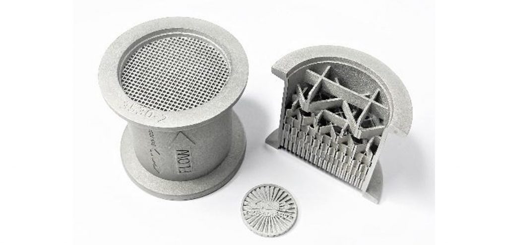
To study the impact of the build process on microstructure and mechanical properties, the role of various process parameters, such as the layer thickness, build speed, the effect of solvents, binder ratio, and post-processing methods, were analysed and discussed. The samples fabricated exhibited a dimensional accuracy greater than 95% along with appreciable green strength, highlighting the potential for its use in diverse applications such as construction and architectural components, photocatalytic supports, filters, and membranes. These findings demonstrate the potential of Binder Jetting to contribute to sustainable glass recycling, with promising applications in industries that require high-precision, functional materials.
The Binder Jetting of aluminium and aluminium alloys
The AM community has always been highly attracted to the Binder Jetting of aluminium and aluminium-based alloys due to their low density, high thermal conductivity, and relatively low cost. Melt-based processes have extensively used aluminium and aluminium-based alloys. However, despite their potential, their use in Binder Jetting has been limited due to the challenges associated with sintering this class of material.
Reducing sintering deformation of aluminium
‘Material and Process Optimization of Binder-Jetting to Reduce Sintering Deformation of Aluminum’, by Takafumi Sasaki and Daichi Yamaguchi, both from Ricoh, focused on the processing of this challenging material and discussed the latest developments in reducing sinter deformation during the manufacturing of aluminium components using BJT. Aluminium is one of the materials of focus for Binder Jetting due to its suitability for applications such as thermal management and its ability to be lightweight when designing for Additive Manufacturing.
The authors outlined the difficulties associated with the consolidation of aluminium alloys with sintering. Some of the problems include:
Oxide layer formation
Aluminium powder is highly active and readily forms an oxide layer with a melting point of over 2,000°C. This layer must be broken up to enable sintering.
Melting point constraints
Aluminium itself has a much lower melting point (around 600°C), meaning the sintering temperature cannot be raised enough to melt the oxide layer without fully melting the aluminium, making shape retention impossible.
Liquid phase sintering challenges
Aluminium is typically sintered using liquid phase sintering, which causes greater deformation compared to the solid phase sintering used for materials such as stainless steel or titanium.
To overcome this issue, Ricoh is taking a multi-pronged approach that includes developing materials such as powders and binders, process developments such as build, debinding, and sintering parameters, and component design to minimise and anticipate deformation. As a result, sinter deformation has been significantly reduced.
Key strategies discussed by the authors include the manipulation of the powder particle size distribution, the use of some eutectic liquid phase formation, the use of some impurities (which were, understandably, not disclosed during the presentation)and some bonding strategies. The necessary liquid mass for sintering is around 20-30%, with the combination of pure aluminium and eutectic aluminium helping; the larger pure aluminium powder particles can be a part of the rigid skeleton resisting deformation to some extent while the eutectic aluminium can form the liquid to promote sintering.
As with all AM processes, the part cost of components manufactured with this technology is often higher than those manufactured by conventional methods. However, there are some examples of its use in full-scale mass production. The authors hope to overcome this barrier by applying life cycle assessment and life cycle cost analysis methods to AM.
The Binder Jetting of 6061 aluminium
Nicholas Murphy from Kymera International gave another presentation on Binder Jetting of aluminium alloys titled ‘Advancements in Sintering and Distortion for Mass Production of Binder Jet Aluminum 6061.’ Their work was carried out on an ExOne Innovent BJT machine that featured an enclosed glovebox for the safe handling of reactive powders such as aluminium alloys.
Murphy acknowledged that though aluminium Binder Jetting shows excellent potential for high-throughput part manufacturing, many challenges remain in bringing the process to a state of mass production readiness. The study focused on using a continuous belt furnace to sinter BJT aluminium 6061 material in a nitrogen atmosphere.
The investigation outlined the factors that affect the distortion of aluminium BJT parts to control distortion behaviour. The author concluded that consistency between sintering runs remained elusive. Further research will focus on optimising sintering conditions, including cycle speed, length, heating and cooling rates, and gas flow rates.
Using HIP to enhance steels produced by BJT and MJT
Matthew Guile from Azoth presented an insightful investigation resulting from a collaboration between Azoth, Lehigh University and Quintus Technologies. The presentation was titled ‘Hot Isostatic Pressing of Additive and Micro-Additive Manufactured 316L Stainless Steel via Metal Binder Jetting and Metal Material Jetting’.
Hot Isostatic Pressing (HIP) is a post-process heat treatment primarily used to improve density and mechanical properties in metal components. Many industries, including aerospace, automotive, and healthcare, widely use HIP as part of their manufacturing processes.
Modern HIP equipment has ushered in rapid cooling or quenching within the HIP process, which allows for better microstructural control within a single-step process. In the past few years, sinter-based AM, especially BJT, has continued to grow in popularity due to its cost efficiency, medium-to-large-scale production, and a diverse range of available metal powders. However, another sinter-based AM technology that has shown some promise in small component manufacturing is Material Jetting.
The team designed an experimental matrix for the HIP of 316L stainless steel manufactured using both Binder Jetting and Material Jetting, consisting of three temperatures of 1,000, 1,150, and 1,250°C and pressures of 100, 140, and 207 MPa. To analyse the results, scanning electron microscopy (SEM) and scanning transmission electron microscopy (STEM) were used to characterise the resulting microstructures following each processing condition, including microstructural phases, defects, inclusions, and their morphologies. Bulk density was also measured to determine the effectiveness of HIP parameters, while tensile properties and microhardness were measured to assess their mechanical performance.
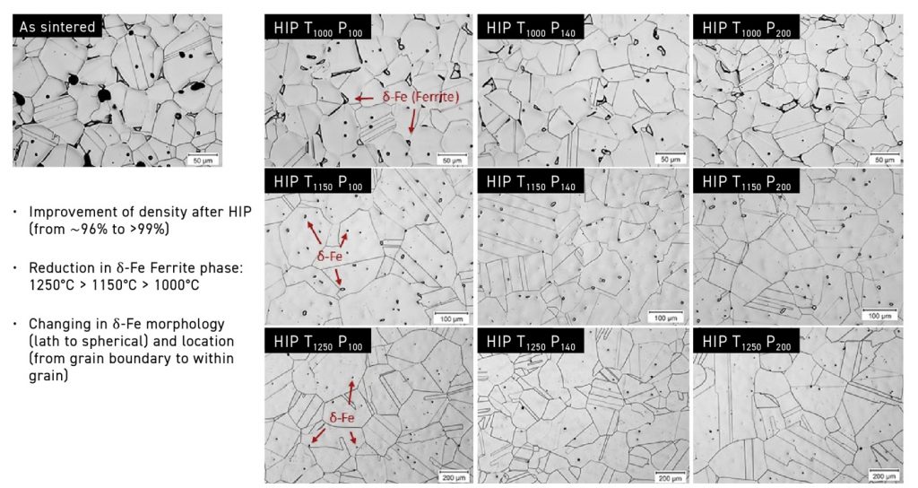
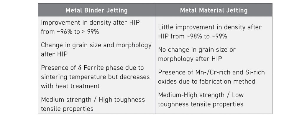
Fig. 7 shows the microstructures of BJT parts sintered and HIPed at various conditions. Table 1 shows the conclusions drawn from Binder Jetting and Material Jetting combined with HIP.
Binder Jetting of high-alloyed steels: innovations in tooling
Simon Höges from GKN Additive presented the successful use of BJT high-alloyed steels in his presentation titled ‘Binder Jetting of High Alloyed Steels – Advancements in Tooling’. Höges highlighted that AM is being increasingly used in the tooling industry, particularly to produce injection moulding tools with conformal cooling channels. The design freedom offered by AM enables significant improvements in heat management; conformal cooling is expected to have a considerable impact on production yield and moulding cycle times.
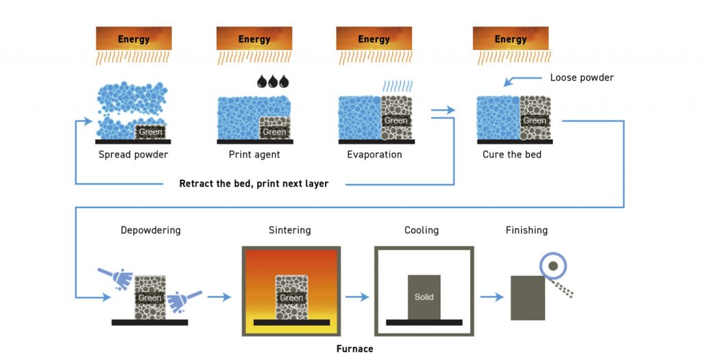
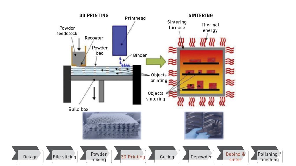
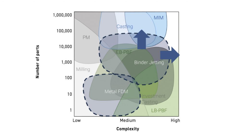
Binder Jetting combines efficient build processes and consolidation through sintering, bringing a wide variety of hard-to-weld materials to the forefront. Fig. 8 shows a schematic of the BJT process, and Fig. 9 shows a schematic that outlines some of the application zones occupied by various metal shaping processes, including Binder Jetting.
Höges’ presentation addressed multiple tool steels, such as M2, H13, and S7, along with their application in different tooling industries. Table 2 shows the results of BJT processing of M2 tool steel, and Fig. 10 displays a microstructure of the M2 tool steel.
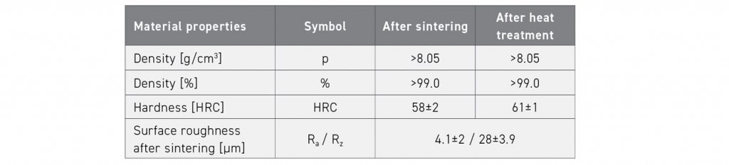
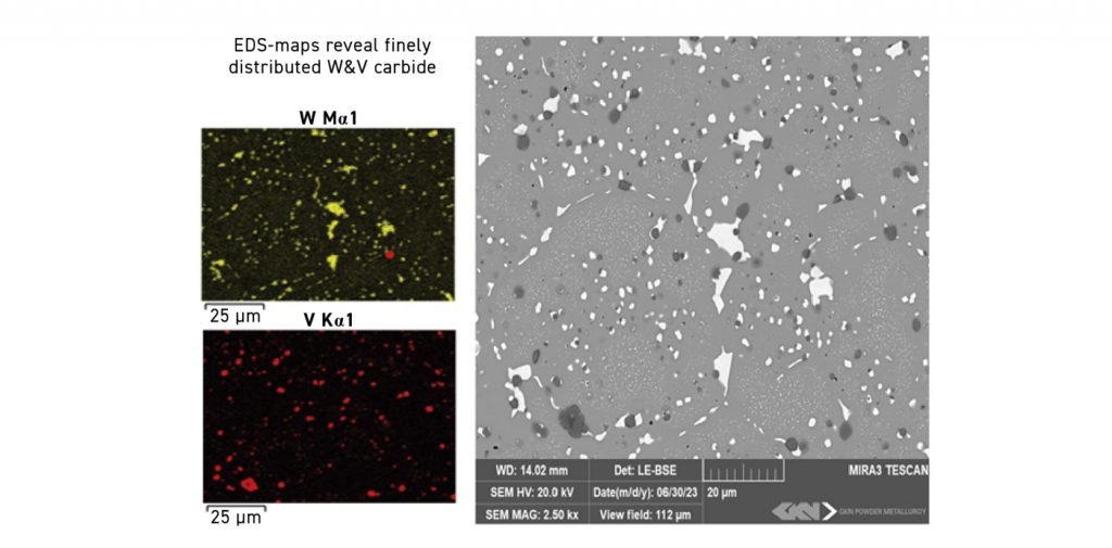
Fig. 11 shows complex geometries produced by BJT-processed hard and non-weldable M2 tool steel. According to Höges, BJT offers a better economic solution compared to PBF-LB, especially when larger volumes of parts are concerned.
Metal powders for Binder Jetting
Key powder considerations for mass production
Another paper on Binder Jetting, presented by Mukund B Nagaraj from Indo-MIM, was titled ‘Key Considerations in Powder Parameters for Mass Production of Binder Jet 3D Printed (BJT) Components’. One key point of interest was the use of a special custom-made grade powder developed by the company for BJT.
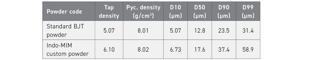
The presentation outlines the differences between the custom-made grade 316L powder and the standard powder for Binder Jetting. Table 3 outlines some of the characteristics of the two powders used in the presentation.
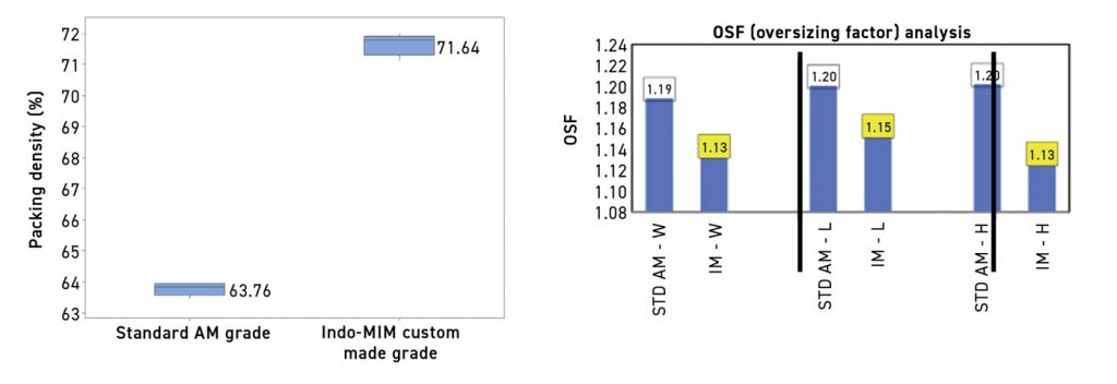
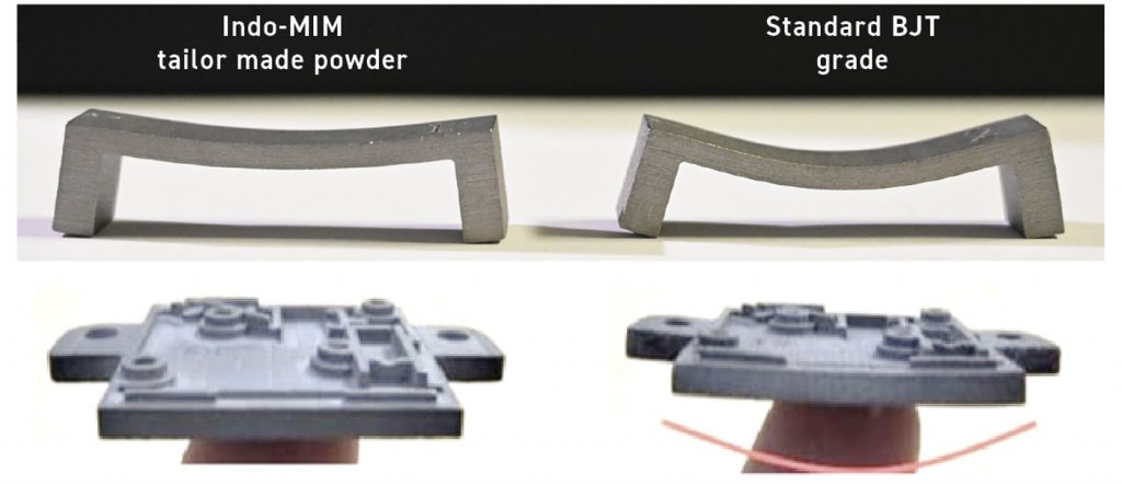
The Indo-MIM custom-made powder exhibited a significantly higher packing density compared to the standard BJT powder, shown in Fig. 12. As a result, the new powder’s shrinkage is significantly lower, as seen in Fig. 13, which shows the oversize factor analysis of the two powders – an indicator of shrinkage. The lower shrinkage translates into lower distortion and better shape retention with the Indo-MIM custom-made powder, as shown in Fig. 14.
Metal powders for sinter-based technology
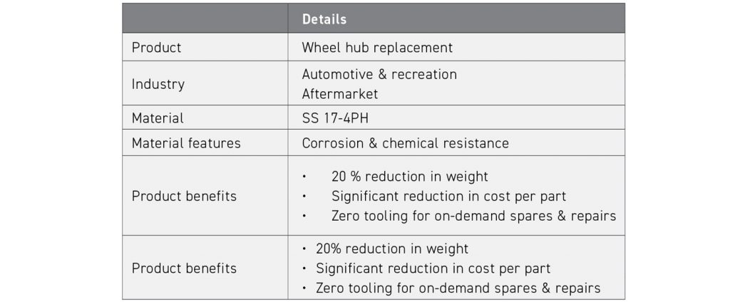
Another paper, ‘Metal Powders for Sinter-Based Technologies’ by Rohit Reddy from Endeavor 3D, discussed the necessary steps to qualify and produce parts with a new metal powder. In the area of spares, repairs, and replacement parts, Reddy spoke about the processing of a wheel hub replacement part made from 17-4 PH stainless steel. Table 4 shows the details of the product.
According to the authors, some of the best practices in powders included the following:
- Storing powders in a controlled environment to prevent contamination and corrosion
- Testing material flow and powder morphology regularly
- Eliminating cross-contamination from depowdering equipment
- Baking and sieving powder between jobs to remove contaminants and residual binder
- Tracking powder usage with lifecycle management
The best practices in sintering include:
- Preventing material and supply cross-contamination
- Calibrating furnace temperatures for consistency
- Designing setters using Design for AM (DfAM) for optimal sintering
- Following safety protocols
- Paying attention to safety considerations
- Tracking data for quality assurance
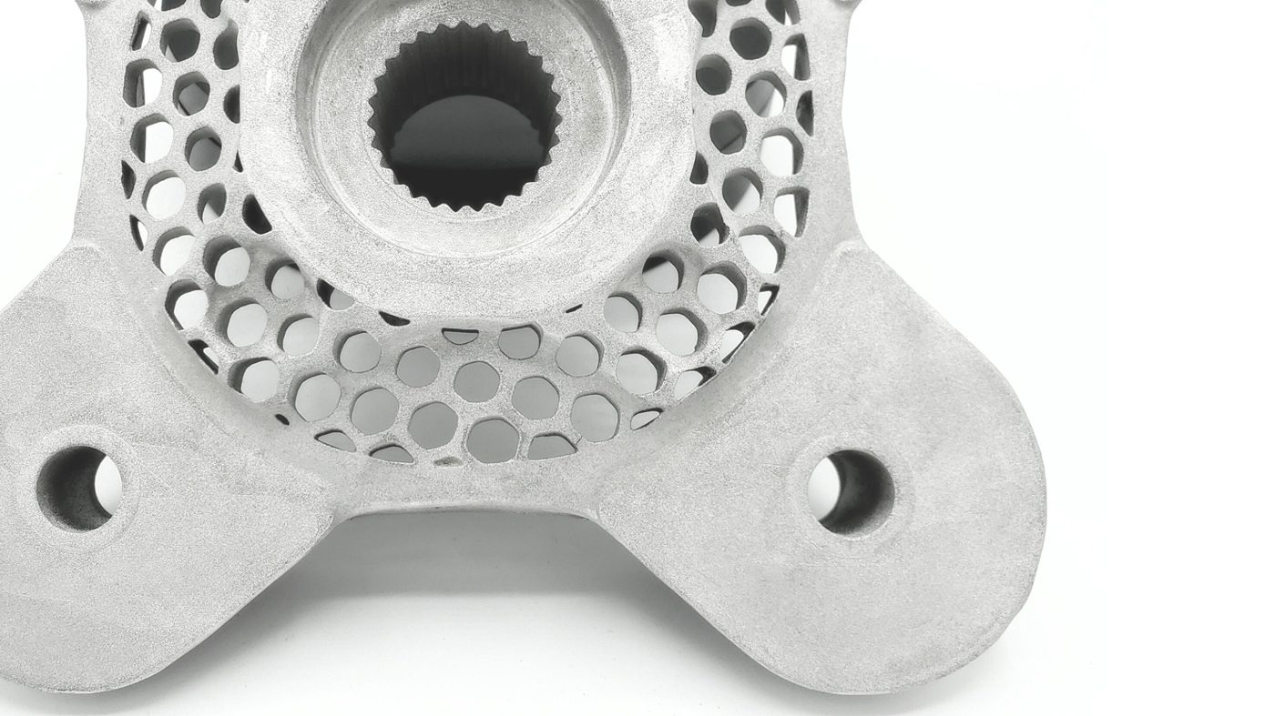
Fig. 15 shows a wheel hub replacement part that the company is producing. The author concludes that BJT is best positioned as a casting alternative for on-demand spares and repairs and is arguably the most scalable metal AM technology. Success in AM requires a commitment to quality assurance and testing.
Overcoming challenges in BJT part production
Several other presentations, made by different organisations, covered other areas of the Binder Jetting process. Three of those dealt with overcoming issues of part production.
Production-ready metal BJT
Ross Adams from Markforged presented one key approach to overcoming these part production challenges in his presentation ‘Production-Ready Metal Binder Jetting through Precision Machine Designed Printer’. By focusing on precision engineering, Adams explained how precision engineering not only prioritises quality, reliability, and repeatability but also serves as a cornerstone for seamless production operations. By operationalising metal Binder Jetting through an investment in a robust platform, manufacturers can achieve heightened uptime, increased yield, and prolonged operational longevity – essential factors for contracted serial production.
The presentation discussed how precision machine design can significantly enhance the efficiency and viability of metal Binder Jetting processes across a wide range of industries.
Prototype to mass production
A paper that also dealt with mass production using Binder Jetting was from Eaton Corporation and presented by Jinjie Shi. The presentation was entitled ‘Challenges and Approach to Turn Binder Jet from Prototype into Mass Production’. The author mentioned that the tremendous amount of effort in developing BJT applications was mainly devoted to prototype demonstration, with only a few successes in mass production. The key challenge is how to control the long-term process capability of the Binder Jetting lifecycle to deliver parts with repeatable geometry and material properties. The presentation outlined the key approaches to overcome the challenge of turning binder jetted components from prototype into mass production.
HP’s approach to scalable Binder Jetting production
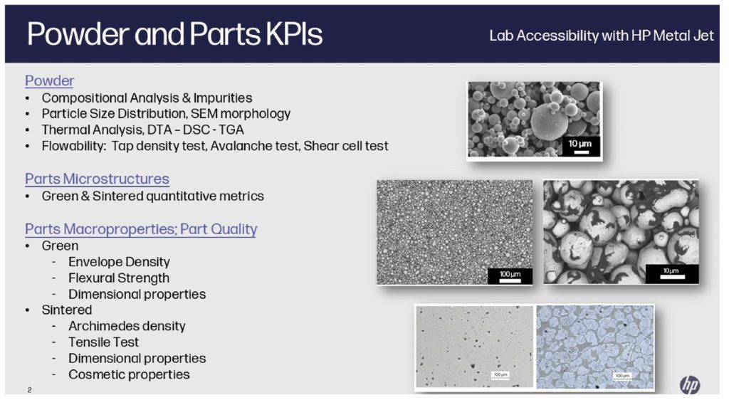
Brett Harris gave another presentation dealing with production using Binder Jetting from HP entitled ‘HP Metal Jet S100: Adoption to Production Solution’. The presentation discussed the benefits of HP Metal Jet manufacturing solutions, which include its robust architecture design, its complete powder and parts handling modules, the predictable part quality performance for a variety of production types and the overall operating efficiency of the equipment. The speaker also examined a range of industrial application cases.
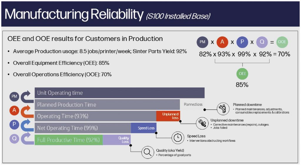
The presentation considered the issue of reliable part quality using key metrics known as Overall Equipment Efficiency (OEE) and Overall Operational Efficiency (OOE). Fig. 16 schematically shows some of the factors that affect OEE and OOE. Fig. 17 shows the laboratory analyses carried out, starting with the powder feedstock through to the green part and the finished part. The overall presentation focused on building a credible ecosystem by offering solutions to various stages of the Binder Jetting process, from raw materials to post-processing.
Other sinter-based AM processes and hybrid approaches
Though Binder Jetting has established itself as the sinter-based AM technique capable of moderate to high volume production of complex shaped parts in an economical manner (as evidenced by roughly half of the presentations in the sinter-based AM track being on Binder Jetting), there are numerous other sinter-based AM processes at various stages of development. Some hybrid processes modify the BJT process, while others differ entirely. It would not be possible to cover all the different sinter-based AM processes covered in this conference track, but we will focus on a few selected presentations.
Multi-material AM for sinterable materials
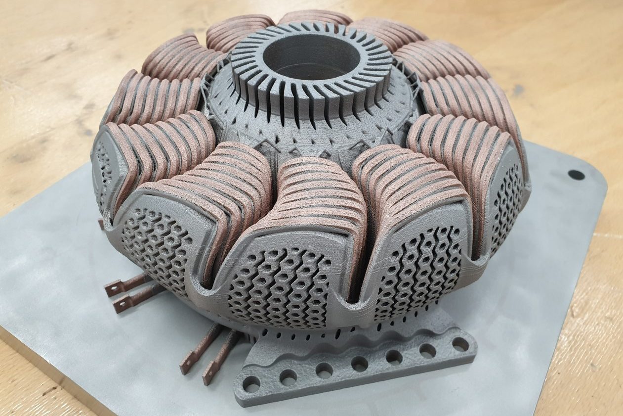
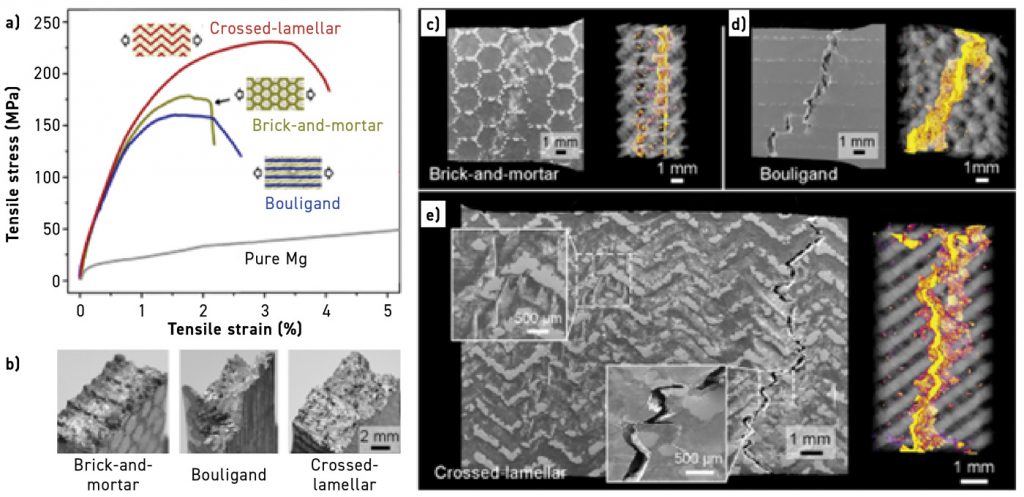
Amy Elliott, from Oak Ridge National Laboratory (ORNL), gave an interesting presentation on sinter-based AM processing. The presentation, entitled ‘Multi-Material Additive Manufacturing for Sinterable Materials’, discussed the Binder Jetting of multi-material, with an example of this shown in Fig. 18. Fig. 19 shows examples of three types of multi-material layup structures (crossed-lamellar, brick-and-mortar, and Boulingand) and their tensile stress-strain curves, failure modes, and fracture surfaces.
In her presentation, co-firing or co-sintering multi-materials was extensively discussed, along with the challenges. As a way of overcoming some of the co-sintering challenges, Elliott mentioned Spark Plasma Sintering (SPS) as one of the processes that could enable multi-material AM processing to overcome the sintering challenges. Some of the advantages mentioned include:
- Reduced sintering time and thermal gradients
- Reduced sintering temperatures (reduces thermal expansion)
- Added pressure avoids tension-based tearing
- Provides more control over heating/cooling rates to synchronise shrinking behaviour
- Yields smaller, more uniform grain size (large grains shrink at different rates than small grains)
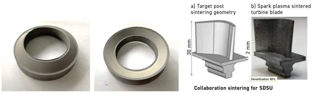
Fig. 20 shows some examples of near-net-shaped BJT parts combined with SPS consolidation (the part on the right was a collaboration effort with San Diego State University).
Fabrication of powder components for advanced applications
Olevsky gave another presentation titled ‘Additive Manufacturing and Spark Plasma Sintering: Fabrication of Powder Components for Advanced Applications’, in which he described a novel method that combines the Additive Manufacturing technique of solvent jetting and Spark Plasma Sintering (SPS) to produce complex ceramic and metallic parts for advanced applications such as biomedicals and optical components. This innovative net shaping approach synergistically combines the capabilities of AM and SPS to produce complex-shaped components with internal channels.
According to Olevsky, along with geometric customisation of the additively manufactured mould, this process offers a significant advantage by drastically reducing debinding time compared to other AM methods. In the presentation, he described how they processed high-density ceramics (alumina, hydroxyapatite, and tungsten carbide) and metallic (stainless steel 316L) complex-shaped parts with internal channels, successfully fabricating them to near theoretical densities.
The studies conducted include the development of a model (based on the continuum theory of sintering formulations embedded in a finite element code) capable of predicting the evolution and/or distortions of the complex-shaped powder assembly during the consolidation process.
Material Extrusion and VAT Photopolymerisation
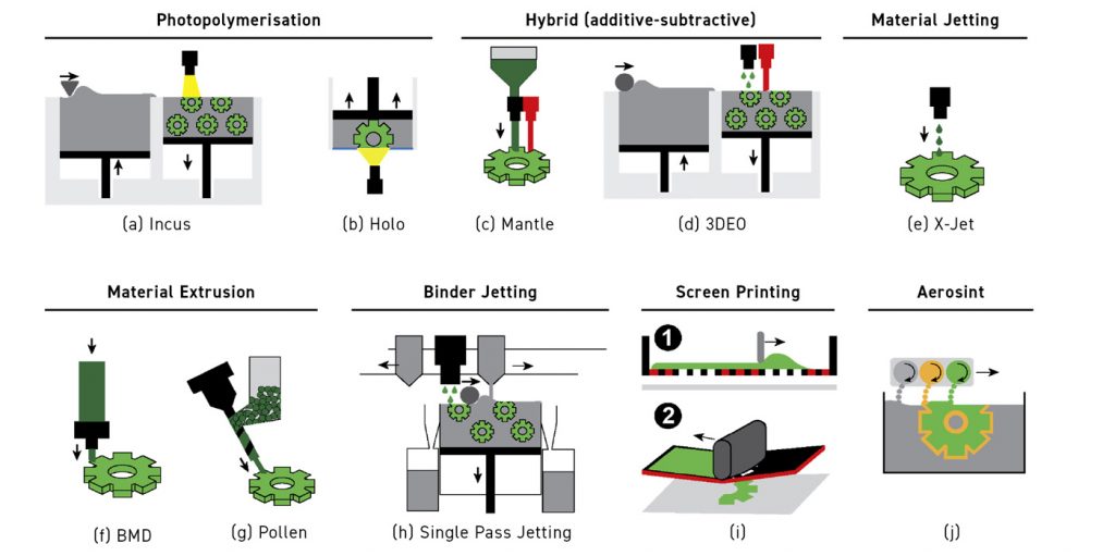
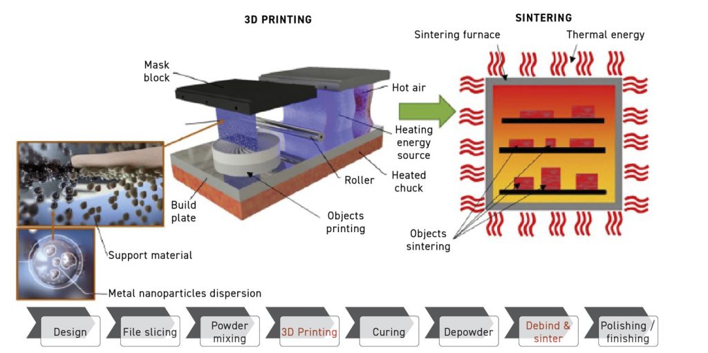
A presentation by Animesh Bose (yours truly) from AMfgLabs LLC, ‘Select Case Studies on Material Extrusion and Vat Photopolymerisation-based Metal AM Processes’, described several of the metal AM technologies (shown in Fig. 21) and then explained in more detail the process and some applications of Material Extrusion and Vat Photopolymerisation. Both processes have similarities with the well-established Powder Injection Moulding process, with MEX being similar, except for the green part forming process. Fig. 22 shows the schematic of three different MEX material delivery types based on (a) filament-based; (b) rod-based; and (c) pellet-based feedstocks.
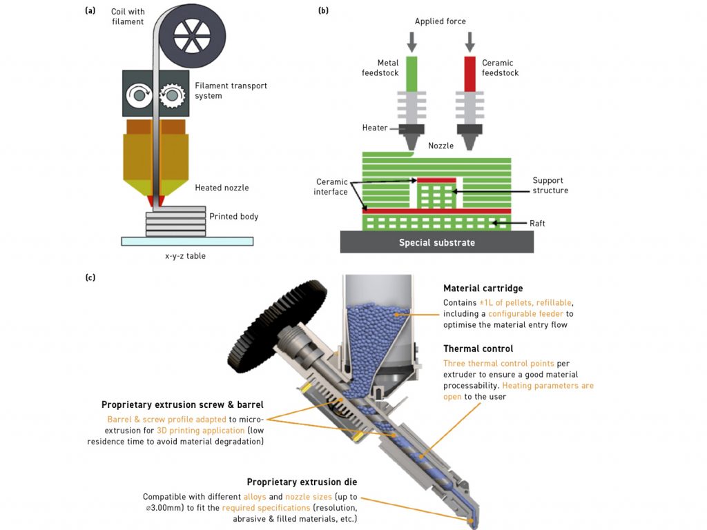
Filament-based feedstock
The filament-based feedstock is a process where a feedstock based on a metal powder and binder mix (such as a MIM feedstock) is fabricated into a precise diameter filament that is then coiled onto a spool. The material for extrusion is supplied as a filament that is fed to the heated section of the extruder using wheels that have tiny gear-like teeth.
Rod-based
In this case, the MIM-like feedstock is formed into precision rods (typically with a diameter of 6 mm and length of 150 mm). The rod is pushed toward the heated section of the nozzle for extrusion using a finger-like device that pushes down on the cold end of the rod. Desktop Metal uses this process, which is known as Bound Metal Deposition (BMD).
Pellet-based feedstocks
In the last case, the MIM-like feedstock in the form of pellets is fed into a hopper through which the feedstock pellets are fed into a proprietary extrusion screw and barrel that forces the pelletised feedstock through a heated die and is extruded to form the part. This is a process developed by the company, Pollen. In another version of pelletised feedstock extrusion, the extrusion is carried out using a plunger that forces the material out through a heated die to result in the desired extrudate; this process is used by AIMD3D, Germany. Fig. 23 shows the as-built and as-sintered hardmetal part fabricated by MEX.
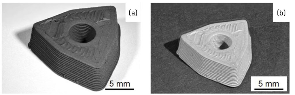
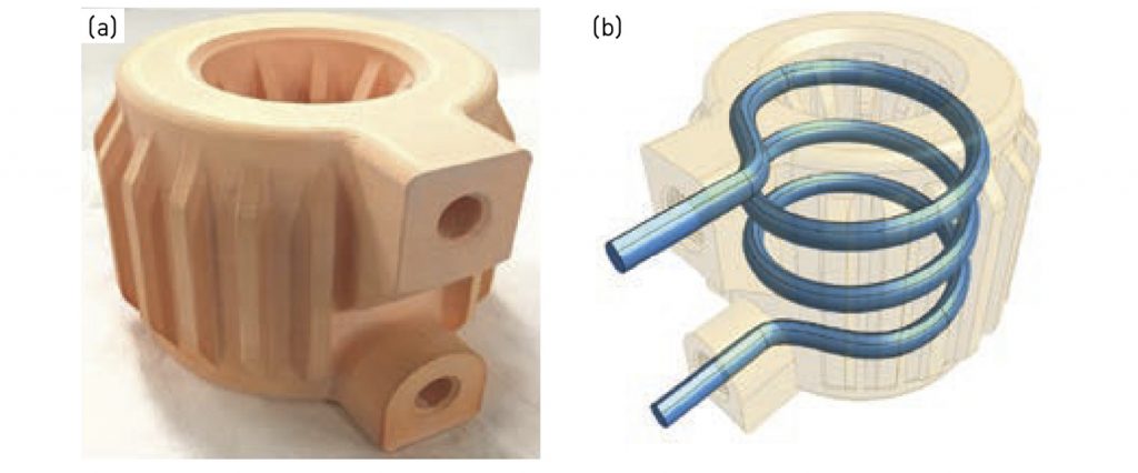
Fig. 24 shows a copper heat exchanger used in chemical processing fabricated by the bound metal deposition process. The part also included a cooling channel, as shown on the right side of the figure.
VAT Photopolymerisation and lithography-based processing
The presentation also discussed the process of VAT Photopolymerisation or lithography-based processing of both metals and ceramics.
One of the companies using the Lithography-based process is Lithoz. In their process, once the digital file is in the machine, metal or ceramic slurry is automatically dispensed into a vat. The build platform is then dipped into the slurry, which is exposed to light from below. This cures the entire surface of a layer at once (where the light shines), considerably speeding up the process compared to laser-based technologies. After the parts are built up, they undergo a debinding and sintering process to yield fully dense and high-performance additively manufactured parts. With Lithoz’s new multi-material AM technology, AM is not restricted to single-phase materials.
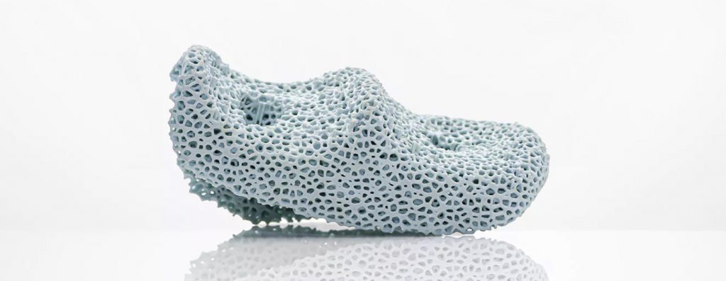
The CeraFab Multi 2M30 uses the full capability of AM to enable the combined processing of different materials, such as ceramics, metals and polymers, and their properties in one single component. Fig. 25 shows a ceramic component fabricated using the Lithoz process. Incus, an evolution of Lithoz, has introduced a new series of metal AM technology capable of producing metal parts with excellent surface quality and high reproducibility.
Bose also addressed another lithographic process used exclusively for metals developed by Incus. The company’s AM machines fabricate green parts from a photoreactive, metal-filled feedstock using a high-performance projector, resulting in accurate and precise green parts similar to parts fabricated by Metal Injection Moulding. Similarly to MIM parts, they require a debinding and sintering process to yield the final metallic properties.
In this case, the light exposure is from the top (unlike the Lithoz process, where it is from the bottom). Metallic parts with excellent resolution can be achieved by this process, as shown in Fig. 26, which shows some cell phone components made by this process.

Biomedical advances
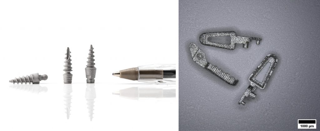
A presentation by György Harakály from Incus also discussed the Incus process in more detail in his presentation ‘Recent Advances in the Biomedical Field with the Lithography-Based Metal Manufacturing Process.’ His presentation delved into recent advances in the biomedical field, highlighting examples of applications in dentistry and surgical tools. Fig. 27 shows some small parts made from titanium (left) and 316L (right). The picture on the right shows 316L as-sintered micro-parts measuring 3.7 mm x 1.2 mm x 0.8 mm; when the pieces are combined, the total weight is 9 mg.
Cold Metal Fusion
Christian Fischer from Headmade Materials presented a relatively novel process known as Cold Metal Fusion in ‘The Power of Cold Metal Fusion’. The process involves the use of relatively fine feedstock made using a mix of organic binder with metal or alloy powder (such as MIM feedstock). The feedstock is formed into fine particulates that can be spread on a powder bed (like the powder bed used in binder jets). A laser beam then exposes the spread powder layer, similar to polymer PBF-LB. The laser melts the organic binder in the powder particles, causing the powders to stick together only in the areas exposed to the laser.
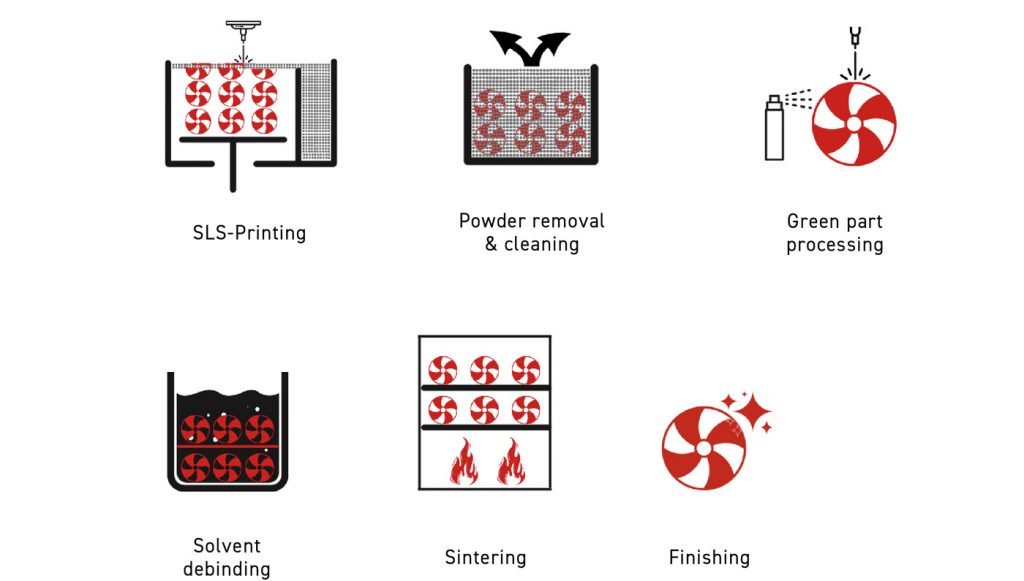
After the full bed of parts has been fabricated, the supporting loose powder is separated from the parts. The parts are quite strong and can even be cleaned by water jet processing. After the powder is removed and the parts cleaned, further processing of the as-built green parts can also be done (as these green parts are quite strong). The green parts can then be subjected to a solvent debinding step, like MIM, where part of the organic binder is removed. After solvent debinding, the parts are moved to the sintering furnace, where they are sintered to near full density.
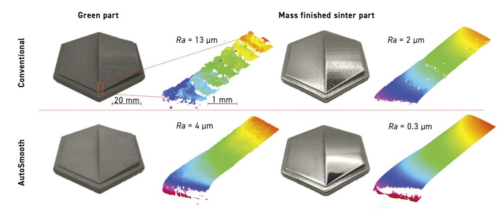
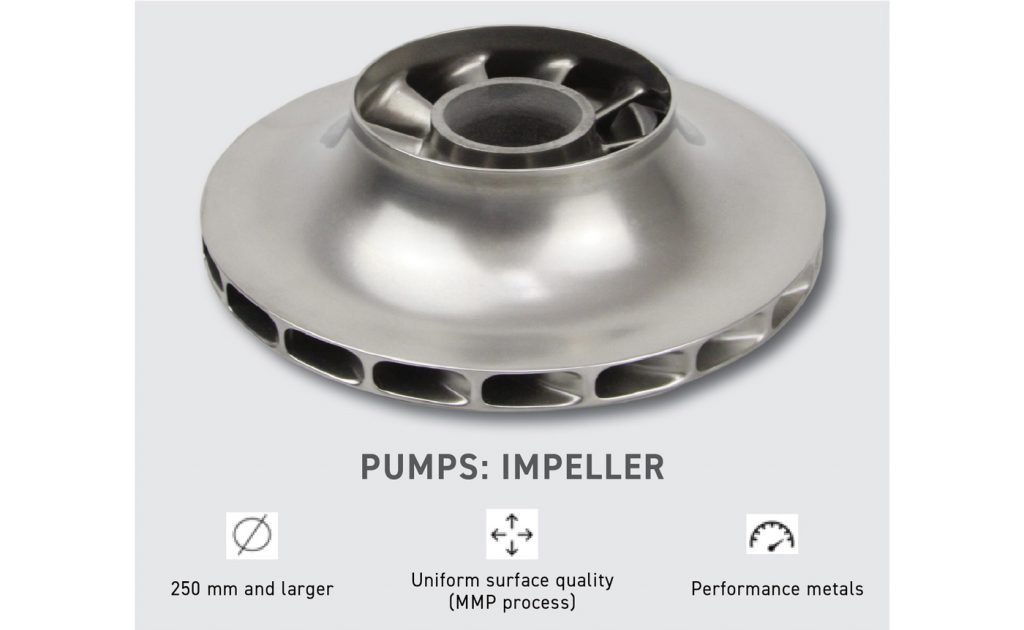
Post-sinter finishing operations can also be carried out. Fig. 28 shows the general processing steps of this Cold Metal Fusion (CMF) process. Fig. 29 shows the AutoSmooth feature of the processing, which would result in mass-finished sintered parts with a better surface finish. The removal of the step effects using the AutoSmooth process results in a better surface finish after the mass finishing step. Fig. 30 shows a pump impeller made by the CMF process.
According to Fischer, the transition from prototyping and small-series manufacturing to industrial series production can be achieved through the CMF process. By leveraging proven equipment and market-available know-how, CMF simplifies the step into industrial series production, enabling outputs in double-digit tonnes per year with just one AM machine.
This integration of AM’s flexibility with the scalability of the sintering process marks a significant advancement in industrial AM. Thus, Cold Metal Fusion combines AM flexibility with the maturity and scalability of the sintering process, resulting in a solution that enables the rise of industrial AM.
Binders for sinter-based AM processing
Another interesting presentation that delved into the binders for sinter-based AM processing was given by Dustin Gilmer from the University of Tennessee Space Institute, entitled ‘A Review of Binders and their Importance for Bind and Sinter Additive Manufacturing’. In the presentation, Gilmer covered a wide range of binders and their uses in sinter-based AM processes.
The author’s conclusion was that binder chemistry is a key to sinter-based AM processes; improved part properties and processing can be achieved by tuning the binder chemistry, and every sinter-based AM process has its unique binder needs. In his presentation, Gilmer pointed out that various binders serve different purposes in the wide variety of sinter-based AM processes. As an example, he has discussed the importance of lubricants that can improve the flow and extrusion properties with smooth extrusion and consistent flow that can improve the overall quality of the build. The use of lubricants can also help increase the solids loading.
3DEO and the sinter-based AM of copper
Mahmood Shirooyeh from 3DEO presented a process that is somewhat similar to Binder Jetting but is different in several key aspects in his presentation ‘Sinter-Based Additive Manufacturing of Copper’.
In the 3DEO process, the binder is sprayed over the full layer of the powder bed (after the powder is spread), and a tiny, pre-programmed cutting tool then goes over and machines the part in the desired areas. In the presentation, the powder used was a commercial gas-atomised Cu powder with:
- Particle size distribution of D50 ~ 10 µm / D90 ~ 20 µm
- An apparent density of 4.03 g/cm3 (45 TD%)
- A tap density of 5.03 g/cm3 (56 TD%)
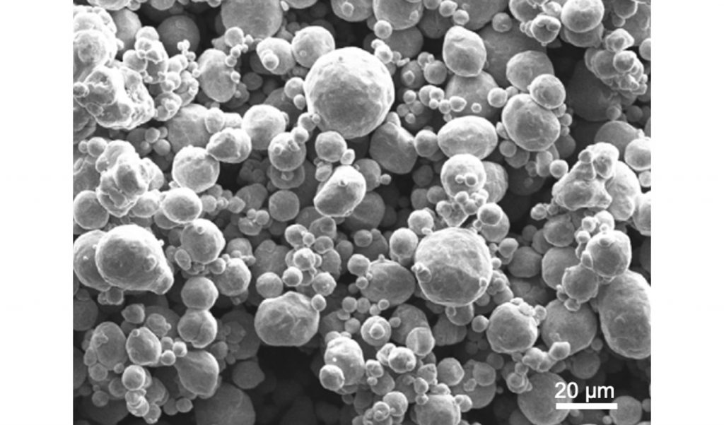
Fig. 31 shows an SEM image of the morphology of the powder used in this investigation. For the build, a 3DEO Saffron machine was used to manufacture the pure Cu coupons. The layer thickness was 100 µm, creating twelve coupons per run (size 6.35 x 30.00 x 30.00 mm).
Sintering was carried out at 1,075°C for 3 h using a H2 partial pressure. The sintered samples were subjected to HIP using a temperature of ~950°C (1,750°F), a pressure of ~100 MPa (14,750 psi), and a hold time of 3 h. The HIP atmosphere used was high-purity argon gas. The microstructure of the sintered and HIPed copper parts is shown in Fig. 32. The as-sintered grain size is around 50-70 μm, and shows anneal twinning, incomplete interlayer pore closure, and anisotropic microstructure. The HIPed parts showed grain coarsening with grain sizes >250 μm.
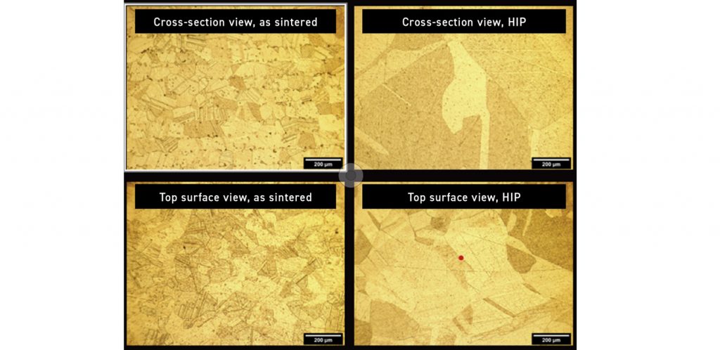
There was also a reduction in interlayer porosity after HIP, which also exhibited more uniform microstructures. The density and electrical conductivity of the parts were measured; the results are seen in Table 5.

Notably, HIPing increases the density from 93 to nearly early 100% of theoretical density, while electrical condutivity rises from 86.3% to 97.4% IACS (International Annealed Copper Standard). Table 6 presents the tensile properties of the as-sintered and HIPed copper parts, showing that the UTS and elongation were increased when the parts were subjected to post-sinter HIPing.

Principles for success with sinter-based AM
Stefan Joens, DSH Technologies, presented on ‘Principles for Success with Sinter-Based Metal AM’. Joens outlined a roadmap for successfully producing parts with sinter-based AM. The key takeaways from the presentation include:
Part design considerations
Emphasising the importance of design in the success of sinter-based AM processes
Customer communication
Stressing the need for early discussions with customers to align expectations and design constraints
Process variables understanding
Addressing the impact of various factors such as powder, binder, and equipment potential on the final part quality
Debind/sinter furnace impact
Detailing how the debinding and sintering processes are influenced by the aforementioned variables
The presentation also provided insights from industry experience, highlighting both the challenges and successes faced by part-makers in today’s manufacturing environment.
Emerging sinter-based AM technologies
In his presentation entitled ‘NextGen-AM – Emerging Sinter-Based Additive Manufacturing Technologies for Sustainable Innovations’, Thomas Weissgärber from Fraunhofer Institute for Manufacturing Technology and Advanced Materials (IFAM) covered several emerging sinter-based AM technologies (other than Binder Jetting). His presentation covered three different sinter-based AM technologies in detail: MoldJet, Gel Casting, and 3D Screen Printing. Fig. 33 shows a picture of some of the AM equipment available at Fraunhofer IFAM Dresden and a graphic representation of the technology envelopes and the areas they cover in the part size versus parts per year chart.

Weissgärber highlights that while PBF-LB dominates metal AM in manufacturing, research, and applications, its limitations in geometry, materials, and productivity are making sinter-based Additive Manufacturing processes increasingly more popular.

Since 2020, most sinter-based Additive Manufacturing technologies have been moving to higher Technology Readiness Levels (TRL), with Binder Jetting being one of the leading technologies in this area. Fig. 34 shows the MoldJet machine concept for Tritone Dominant, outlining the six significant steps in the process.
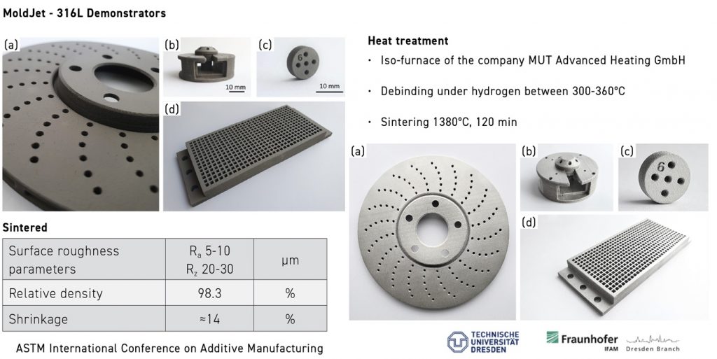
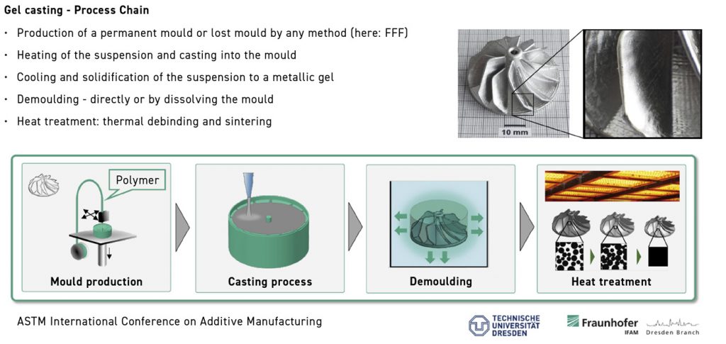
Fig. 35 shows some 316L parts produced using the MoldJet process. Fig. 36 shows the Gel casting process, which begins with creating a permanent or lost mould (made via FFF in the figure). This is followed by casting the desired suspension into the mould by first heating the suspension. Once the suspension is cast into the mould, cooling solidifies it into a metallic gel. Various processes, including dissolving the mould, can remove the part. After demoulding, the part undergoes debinding and sintering to achieve the final metal form. Weissgärber also covered Screen Printing, a technology explored in detail in another presentation from Exentis.
The summary slide was captivating, beginning with the statement, “There is a world beyond laser!… And there is also a world beyond metal Binder Jetting.” Weissgärber concluded that while sinter-based technologies remain niche compared to PBF-LB, they are rapidly gaining traction, with many exciting new sinter-based AM technologies with the potential to improve cost, productivity, resolution, and material variety.
The author also acknowledged challenges, including distortion, maturity, etc. He summarised by saying that companies need to choose the right technology.
Screen Printing
Screen Printing is a sinter-based AM technology that has the capability to fabricate parts at a very high production rate with some limited z-directional shape complexity. Fig. 37 shows a schematic of the Screen Printing process. A detailed description of the Screen Printing process was presented by Eric Bert from Exentis, entitled ‘Additive Screen Printing: Industrialized AM Technology for Powdered Metals, Ceramics, and Beyond’.
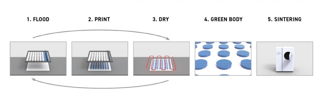
Bert described some of the details of the machine, process, and applications in his presentation. He stressed on-screen tools and optical layer alignment to deliver ultra-fine part features repeatably. High-speed automated systems are important for cost-effective mass production volumes.
An advantage of the process is that the paste feedstock used can be formulated using almost any material available in powder form. However, it is essential to recognise that any change in the XY geometry of a part would require changing the screen tool, which adds cost and time.
Also, the parts would have limited overhangs, though internal channels are feasible. Fig. 38 shows some of the possible geometrical features possible with this process.
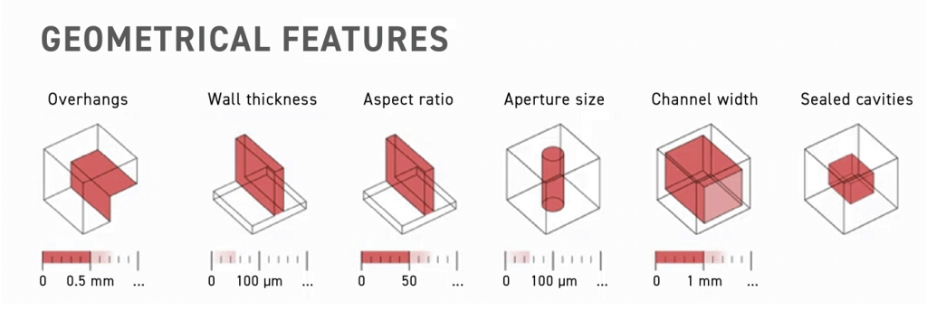
The process can work with numerous materials, including polymers, metals and ceramics. Some of the non-polymeric materials that have been successfully developed include:
- Alumina
- Zirconia
- Silicon carbide
- Aluminium nitride
- BaTiO3
- Various metal matrix composites
- 316L stainless steel
- Pure copper
- 6061Al aluminium alloy
- 4041 quench
- Tempered steel
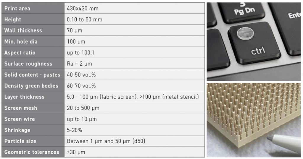
In Fig. 39, process and screen characteristics are shown on the left side of the picture, and a part is shown on the right. Fig. 40 shows the image of 316L filters that were 2 mm in diameter, 600 µm thick, with walls thickness of 100 µm, with holes having a diameter of 120 µm.
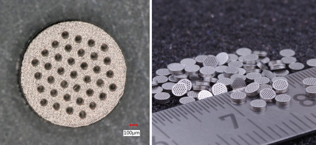
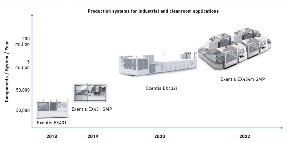
Fig. 41 illustrates the year of introducing several industrial production systems from Exentis versus the production capability of various machines.
Conclusion
This report aims to cover what the author believes were the most engaging presentations given at ICAM 2024 within the sinter-based AM track. While reading a condensed version of the presentation offers valuable insight, attending the conference provides a far more productive and comprehensive experience.
The rapid growth of sinter-based AM is particularly interesting, as it extends beyond a single or limited number of processing platforms. Although Binder Jetting has caught the attention of many large manufacturing companies due to its attributes and the promise of meeting high-volume production requirements cost-effectively, the proliferation of novel sinter-based technologies continues to grow.
Beyond the more established processes, such as BJT and MEX, numerous other technologies are developing. These include Screen Printing, hybrid processes combining additive and subtractive methods, Gel casting, and various MEX variations. The sinter-based AM track within the ASTM ICAM series brings together updates on these new approaches and new materials alongside ongoing advancements in more mature sintering technologies. Readers are encouraged to consider attending the 2025 conference in Las Vegas, Nevada, to explore these exciting developments firsthand.
Author
Dr Animesh Bose
CEO
AMfgLabs LLC
Barnesville, Ohio, USA
[email protected]