Advanced Powder Injection Moulding process developments presented at Euro PM2020
Within the programme of the successful Euro PM2020 Virtual Congress, organised by the European Powder Metallurgy Association (EPMA) and held October 5–7, 2020, a technical session, comprising three papers, addressed advanced process developments in Powder Injection Moulding (PIM). In this review, Dr David Whittaker reports on these presentations that addressed the opportunities around single-use moulds, advanced part customisation, and cobalt-free diamond composite for cutting tool applications. [First published in PIM International Vol. 15 No. 1, March 2021 | 20 minute read | View on Issuu | Download PDF]

Additively manufactured single-use polymer moulds for prototypes and small series production by Powder Injection Moulding
The first paper in this review reported on the development of additively manufactured single-use polymer moulds for prototyping and small series production and was presented by Axel Mueller-Koehn, Eric Schwarzer and Tassilo Moritz (Fraunhofer Institute for Ceramic Technologies and Systems, IKTS, Germany) and Uffe Bihlet and Kyriakos Didilis (AddiFab, Denmark) [1].
In Powder Injection Moulding, several iterations are often required when different aspects of the part design and the production process are tested. This can be a time-consuming exercise, as tooling rework commonly lasts five to six weeks. Of the attempts to address this issue, only the use of soft tooling, made by casting epoxy or AM polymer tooling, has allowed a prototype to be made with the same production process and material as the final part.
The limitations of polymer moulding made by Vat Photopolymerisation (VPP), or stereolithography, are mostly related to the lack of strength, durability and heat resistance of the mould materials used. In a new approach, termed Freeform Injection Moulding (FIM), a dissolvable UV-hardening polymer is used to additively manufacture moulds. FIM has been commercially demonstrated using conventional PIM feedstocks consisting of a polymer-based binder and metal powder. Using a dissolvable mould material removes all mould design restraints, such as draft angles, ejector pins and split lines, and even allows AM-like part designs, which are simply not possible with conventional split tools. Mould deterioration is also not an issue, as the mould material is formulated to dissolve and, therefore, be single-use.
The presented study addressed the process variables required for the application of a specific CIM feedstock with the FIM process and, in addition, sintered test parts were evaluated with reference to dimensional tolerances, roughness and debinding defects.
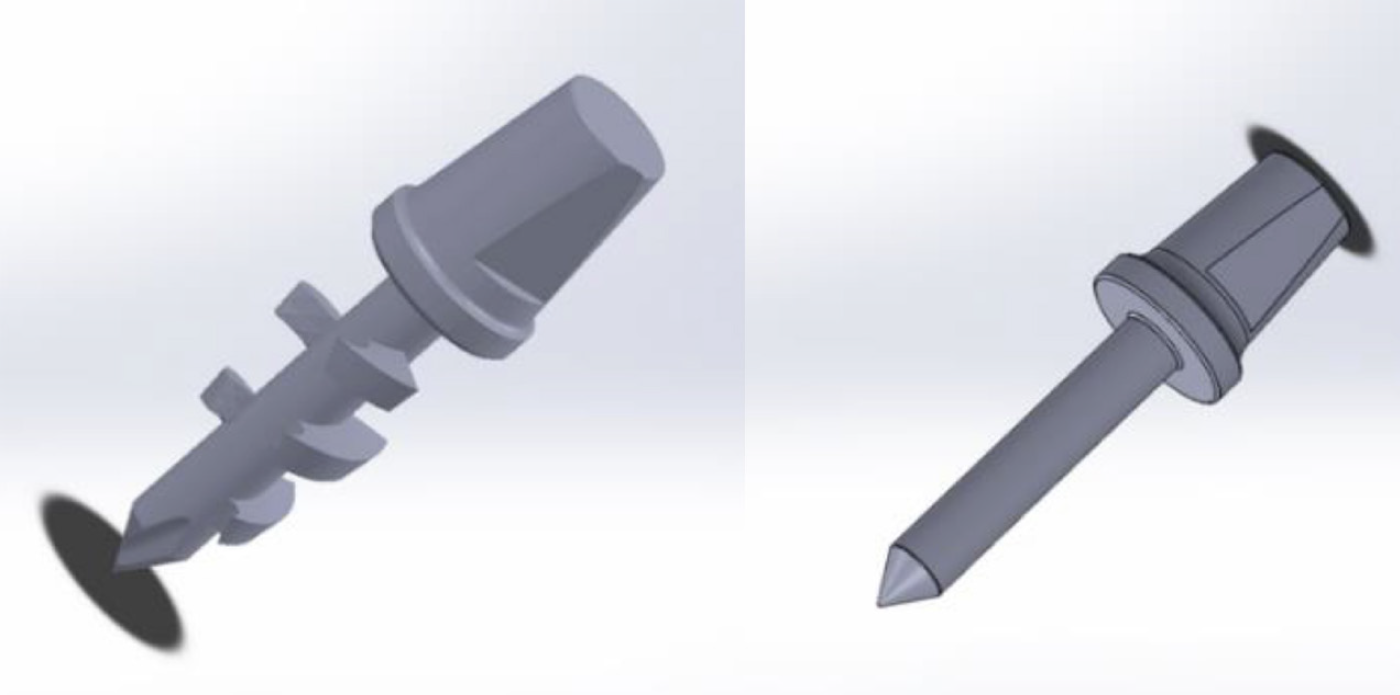
To demonstrate the process, a variant of a bone screw design of approximate length of 18 mm was selected (Fig. 1). A simplified version of the screw without threads was used. The external dimensions of the AM moulds were fixed at Ø35 x 10 mm. The moulds were additively manufactured using an AddiFab system, comprising both software and hardware. The AddiFab AM machine is based on the VPP principle and produces parts from a dissolvable, UV-hardening liquid acrylic resin. Parts were built with a layer thickness of 50 μm, resulting in 200 layers with a build duration of an hour. After the build, the moulds were cleaned and flushed repeatedly with isopropanol at ambient temperature to remove residual resin. The moulds were post-cured with a flood beam system at a UVA range of 320–390 nm with an intensity of 105 mW/cm² for 3 minutes on both sides.
A CIM-compatible vertical injection moulding machine was used for injection moulding. Prior to each shot, the AM mould inserts were manually placed within a steel ‘mother’ mould. A commercial feedstock, based on polyethylene-wax binder components and 99.8% pure alumina powder, was used. The nozzle temperature was 170°C, the steel tool temperature 90°C, the injection volume flow rate 16 cm/s, the maximum injection pressure 950 bar, the holding pressure 500 bar, the injection time 0.3 s and the cooling time 30 s.
Following injection moulding, the AM mould was dissolved in a proprietary AddiFab demoulding agent at a temperature of 35°C. Debinding of green parts was then conducted in two steps: firstly, solvent extraction of wax components was carried out in isopropanol at 70°C for 24 hours and, secondly, thermal debinding was carried out in a convection furnace in air up to 600°C. Sintering took place in air at 1620°C for 2 h with a heating rate of 3 K/min.

Some initial experimentation was conducted on a number of CAD files with regard to the part orientation within the AM mould. It became apparent that overhanging, flat areas perpendicular to the building direction should be avoided, as the lack of support of overhangs during the AM process leads to the sagging of unsupported areas, as shown in the bottom of Fig. 2. This is a phenomenon which is affected by the layer thickness during Additive Manufacturing, as thinner layers are weaker and require better support.
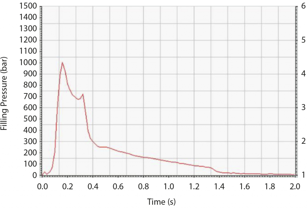
For initial parameter adjustment for injection moulding, a preliminary process simulation in machine mode was helpful. Exact prediction of shot volume was also necessary because testing shots are possible only in AM moulds. In the injection trials, higher mould and feedstock temperatures, in comparison with steel moulds, were applied to enable the suitable flow behaviour of feedstocks, because of the thermal insulating character of the mould resin. In addition, the cooling time was extended. The holding pressure was very effective during freezing because of the slow cooling. In Fig. 3, pressure flow is shown as a function of filling time.
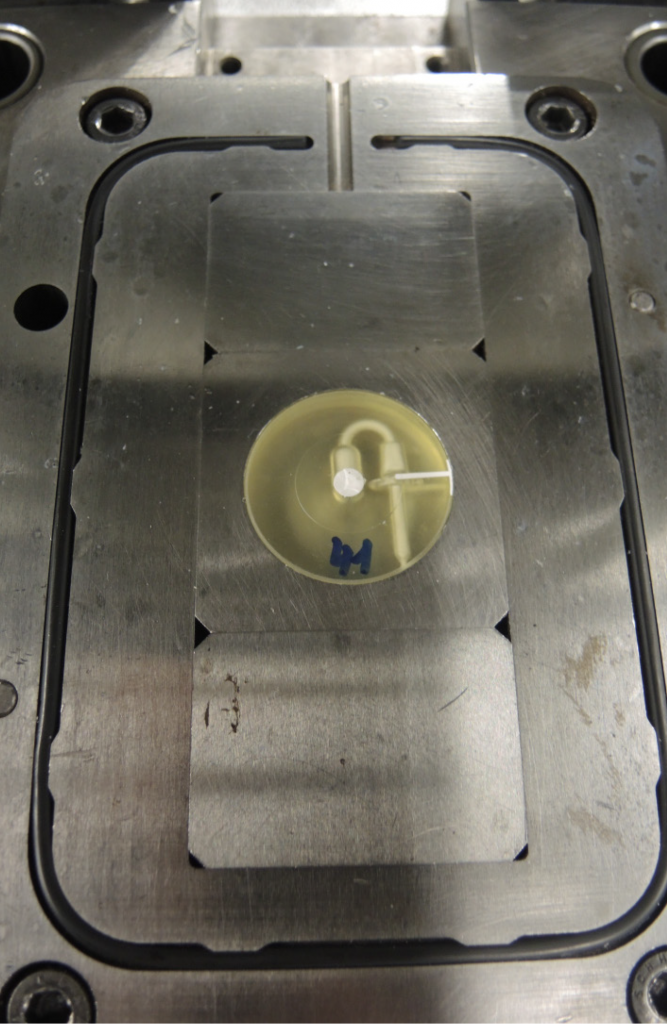
After moulding, the consolidation of melted feedstock is related to the shrinkage of the green body. For PE-wax based materials, a shrinkage of 1.8% is commonly observed. This shrinkage led to separation of the green component from the mould. Cracks only occurred in the venting channels and gating area. The demoulding process proved successful and left the parts with the same shape and appearance as the one within the moulds.
Characterisation of the sintered components identified feedstock shrinkage very close to the specified level, i.e. 18.8% (measured) vs. 18.5% (specified), resulting in a mould factor of 1.23 (1.2006 specified). A sintered density of 3.94 g/ cm³ was reached. These results showed that there is no interaction of mould design, mould material and demoulding procedure with debinding and sintering properties of the applied feedstock, in principle.

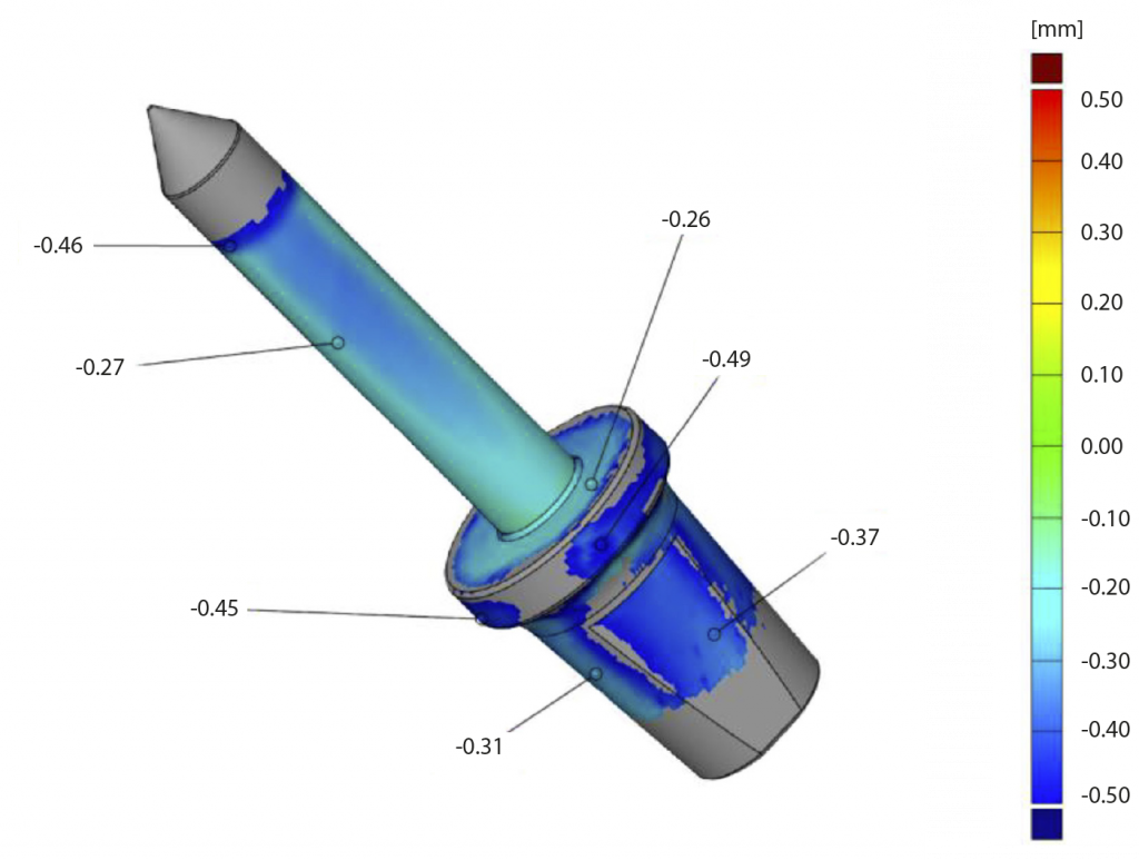
The parts are slightly undersized (Fig. 6), but this deviation is relatively homogenous and could potentially be compensated with an adjustment of the oversize factor. Also, there were no oversized features measured, indicating that an FIM mould can successfully retain its structural integrity with the tested parameters. These parameters can be used as a basis for further improvement.
For conventional injection moulding, polishing of the inner cavities is a way to control the roughness of the final part. With the FIM approach, this is not possible as the mould is closed. Since the mould is additively manufactured layer by layer, the roughness of the vertical features are determined by the layer pitch resulting from the build parameters. For roughness measurements, two mutually perpendicular areas of the screw head were characterised. The area in Fig. 7 is rounded, but surface layer steps of the mould building process are visible. The heights of these steps in sintered components are in range 20 to 30 μm. This corresponds to the applied layer thickness of 50 μm for the AM moulds after sintering.
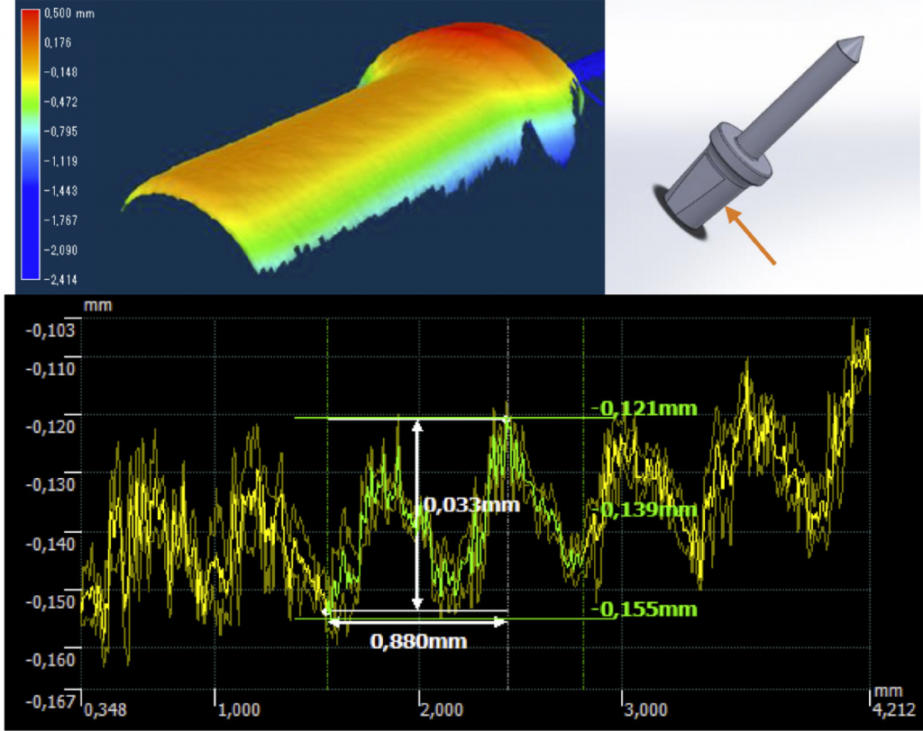
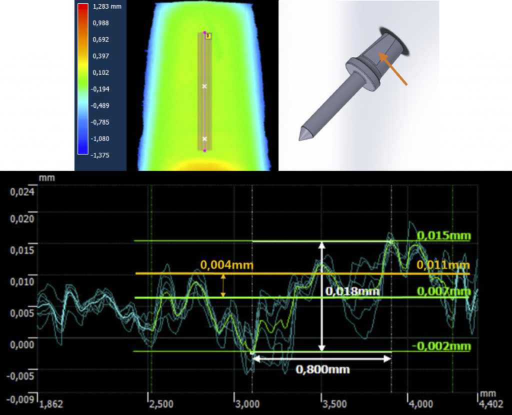
Fig. 8 shows the results of roughness measurements on a flat area. Here, an overall roughness depth (Sz) of 18 μm and an arithmetical mean deviation (Sa) of 4 μm was achieved. It was concluded that the roughness of parts produced by FIM does not deviate significantly from steel moulds and there is room for further improvement by decreasing the layer thickness even further or by testing polishing solutions.
Overall, this study has shown that the FIM approach is fully compatible with CIM; that the application of commercial feedstocks and standard thermal processing is possible; and that the resulting parts have shapes, sizes and finishes similar to those produced by conventional methods.
Advanced shaping possibilities for feedstock-based processes
Next, Sebastian Boris Hein, Janne Haack and Frank Petzoldt (Fraunhofer IFAM, Germany) presented a paper on advanced shaping possibilities for feedstock-based PIM processes [2]. The focus of the reported work was on production concepts that make use of mould inserts to alter the resulting cavity, which is then filled with feedstock during the moulding step. The mould inserts can be used once, or reused, depending on the intention and the material.
The examples given in the presentation included inserts made by various processes. Specifically, silicone foils for surface structuring as well as polymer parts produced by low-cost AM processes such as VPP and Material Extrusion (MEX) processes, for example Fused Filament Fabrication (FFF), were used for experiments.
Depending on the specific process, the inserts were either pre-heated in a furnace, in the mould or not at all. The injection moulding machines used for the moulding experiments were a piston injection moulding machine and a screw injection moulding machine, using base moulds with rectangular-cavities to place the mould inserts inside.
Silicone foils, used for surface structuring tests were made by the casting of a two-component silicone onto a pre-structured metal surface. The surface structure (riblets) was created by machining. After polymerisation, the silicone foil was manually removed from the metal template, cut into correctly sized pieces, and inserted into the base mould prior to feedstock injection.
The approach to structuring the surface of a part targeted different applications. The example given aimed at providing a regular riblet structure onto metal parts, in order to reduce flow resistance in specific applications. Generating such a structure in a metallic material is particularly relevant for thermally stressed parts, where other materials, such as polymers, are not applicable. A further potential application area comes from the medical field, especially for implants, for example to manage cell adhesion, or if they have to form a stable connection with bone, for which a mechanical interlocking may be advantageous.
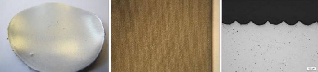
Fig. 9 shows the metal plate used for silicone casting, as well as the structure of an injection moulded green part and a cross section of a sintered part. Unsurprisingly, the rather sharp peaks of the riblets tend to become rounded during sintering. In addition, the relative size of the structure and the powder particles plays an important role in terms of the quality of the final structure. To date, the overall concept is applicable to simple parts, but, in future work, the use of silicone foils to structure specific areas of more complex parts will be investigated. The ease of producing the silicone foils makes the approach quite interesting, in its current state, at least for development purposes.
Polymer parts used as mould inserts were made by the three different processes, two VPP processes (Digital Light Processing (DLP) and Stereolithography (SLA), and FFF. For part tagging with DLP inserts, the inserts contained a Data Matrix code, either as an indentation or as elevated structures. During moulding, the Data Matrix code is transferred to the green part. This study was carried out with the goal of individual tagging of green parts in mind, with regard to ongoing work aimed at process digitalisation and backtracing of MIM parts, starting from the shaping step. The main purpose of this aspect of the study was to identify the conditions resulting in readable codes for green and sintered parts.
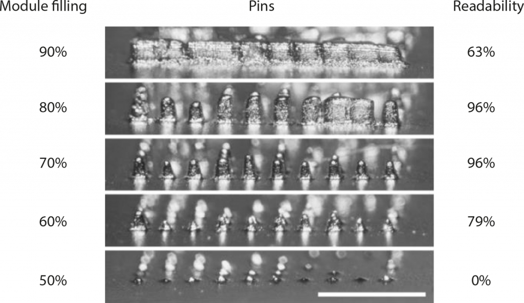
It was observed that the DLP AM of a protruding structure, which would result in cavities in the MIM part, is not feasible on a reliable basis, as the tiny pins tend to be ripped off during the build process. The Additive Manufacturing of cavities shows no problems, but the filling density of the structure matters in relation to the resulting pins of the MIM part. If the pins are too close, the pins grow together during sintering, resulting in reduced readability of the code. Possibly, the thin walls between the cavities in the DLP part become too weak to withstand the injection, which may also be a reason for the reduced pin resolution for high module fillings, especially 90%. Fig. 10 shows this correlation.
As the tags can be generated automatically, additively manufactured in large numbers and used on demand, applicability seems to be assured. For more complex parts, a chosen area of the base mould would have to be left open into which the DLP tags could be inserted. This will be investigated in the future in more detail.
In contrast to the previous concepts that are more likely to be used to alter a specific area of parts, the use of AM parts to provide the entire cavity of the part, as well as the sprue system, has also been investigated. This approach is very close to typical rapid tooling, but with low-cost AM moulds, produced by DLP or SLA.
This concept works in principle with the chosen SLA material. The main observed issues can be attributed to the lack in precision of the SLA process. The outer dimensions of the SLA parts did not fit perfectly into the cavity of the base mould. The high injection pressure during the injection step then led to a slight opening in the mould parting surface. Thus, feedstock overflow and an incomplete filling of thin-walled parts resulted. Nonetheless, parts could be moulded and the moulds were used for seventy-five injection cycles in the case of a crucible mould. The observed issues could be tackled by specific measures, such as building the moulds slightly larger than the base mould cavity and grinding the outer dimension to fit better and using a feedstock with lower melt viscosity to decrease the required injection pressure.
The concept of lost-form inserts was aimed at using materials in combination with feedstocks that can be removed by a physical or chemical treatment that leads to the decomposition of the insert. Thus, the moulded part can be retrieved without mechanical measures, which leads to an increased degree of freedom in design, e.g. undercuts or size-variant channels can be achieved that could not be demoulded with conventional tool technologies. In previously reported work, the group used DLP parts of conventional resin as mould inserts to demonstrate the feasibility of this approach. The resin-based DLP parts are not chemically soluble and were therefore intended to be burnt out during the thermal treatment for debinding and sintering. In several cases, the approach worked well, but there remained a variability in the results that could not yet be resolved and makes this approach currently unreliable.
In order to create chemically soluble inserts, FFF was used for the insert manufacturing, using PVA filament. As PVA is water soluble, moulded parts comprising the PVA insert and the feedstock green part can be submerged in water until the PVA is dissolved. Fig. 11 shows a test geometry in all process steps and the insert placed inside the base mould.
As shown in Fig. 11, this process is feasible, but several technical issues had to be faced. The two major issues were that residual PVA leads to problems during thermal treatment and can damage the part. Also, low green strength of the feedstock is problematic, as the PVA swells during its dissolution and this can induce cracks in the green part. However, the main issue with this approach is the as-built quality of the FFF part. FFF leads to considerably worse surface quality than DLP or SLA and, when a feedstock is injected with high pressure, any insufficient connection between strands can be infiltrated by feedstock, distorting the final part. The approach to remove the insert chemically rather than thermally seems to be the appropriate direction for development.
Based on material development approaches for DLP, hydrolysable parts, with the resulting decomposition products being soluble in aqueous media, can be produced. Currently, AM machines and adapted materials are commercially available for plastic injection moulding and the first encouraging results for MIM and CIM exist. This approach is very promising for materials that do not corrode during the removal of the insert. A combination of the DLP-part removal and chemical debinding may be interesting as a means of saving processing time and is a subject of ongoing research.
Development of a PIM process for cobalt free diamond composite for cutting tool applications
Finally, Iñigo Agote and Cristina Guraya (TECNALIA, Basque Research and Technology Alliance, Spain), Alberto Colella (MBN Nanomaterials SpA, Italy) and Edoardo Nicolis and Marta Dai Pre (DELLAS SpA, Italy) described the development of a Powder Injection Moulding process for cobalt-free diamond composites for cutting tool applications [3].
The current manufacturing process for tool segments for rock cutting uses a pressure-assisted sintering process (uniaxial hot pressing) to obtain fully dense materials at relatively low sintering temperature. This process involves a number of steps: mixing and granulation of the powders (cobalt and diamond), then cold pressing of the mixture and finally sintering under controlled atmosphere and assisted by a mechanical pressure to obtain a fully dense product. This manufacturing route has some limitations, such as the restrictions in the part geometry and productivity of the process.
Called Diamond Injection Moulding (DIM) by the authors, this variant of PIM can overcome these limitations. Therefore, the development of the injection moulding process for this application can bring substantial improvements in terms of productivity and final part complexity. Bearing in mind that machining of these composites is very difficult and costly and, therefore, the reduction in final machining would offer an important lead time reduction and cost benefits.
Nevertheless, the development of a PIM/DIM process adapted to diamond-based composites is not an easy task. While the PIM process allows complex part manufacturing, the uniaxial hot pressing of complex parts is difficult, if not impossible. Therefore, this would require the substitution of the current cobalt matrix by a metal that allows a pressureless sintering process. The PIM process also requires the design of a suitable binder system and feedstock for the process (to allow good injection mouldability, fast debinding and adequate sintering).
In view of this, the aims of the presented study were the substitution of Co as the metallic binder phase by a new non-critical and less toxic alloy and the optimisation of the diamond injection moulding process. The new metallic powder was obtained by a High Energy Ball Milling (HEBM) process and, thus, its physical properties were quite different from standard PIM grade powders. In addition, an ‘ad-hoc’ water soluble organic binder system for the injection moulding process was to be developed to allow a high water debinding rate and thus increase the process productivity.
Elemental powders (Fe, Ni, Cu and P) were mixed in the appropriate ratio and the mixture was ball milled vigorously to create the final alloy (FeNiCuP).
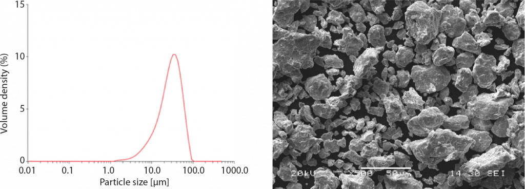
The particle size distribution of the powder, presented in Fig. 12, shows a typical one size log-normal distribution with an average particle size of about 29.1 µm; comparable to most MIM-grade powders. The present alloy, obtained by HEBM, showed an irregular shape with some roundish appearance as can also be seen in the SEM micrograph in Fig. 10. This lack of sphericity may require slightly higher binder content to adapt the rheological properties to the PIM process.
Commercial synthetic diamond with a size D50~300 µm was used. This diamond was coated with TiN to improve the interaction with the metallic matrix and protect it against oxidation. For a gang saw application, a composite with a low amount of diamond was used, typically, 2–3 wt.% of diamond.
The binder system has been designed using three main constituents:
- Low melting point water soluble organic compound: Polyethylene Glycol (PEG)
- High melting point organic compound: Poly methyl methacrylate (PMMA)
- Surfactant: stearic acid (SA)
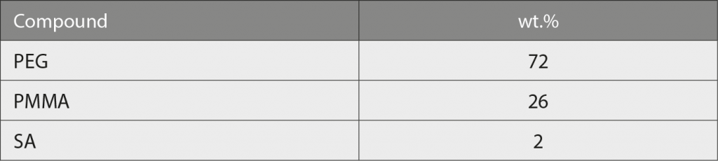
Binder constituents were premixed at high temperatures where all the constitutents were in liquid state. The amount of each constituent was evaluated so that the best binder composition for the injection moulding and debinding steps was obtained. This composition is shown in Table 1.
The feedstock for the injection moulding process was developed using the new alloy, diamond and the organic binder. The initial step was to identify the Critical Powder Volume Concentration (CPVC). This is important because it will allow an efficient process: appropriate injection moulding step, reduction of the debinding time and lower shrinkage during sintering, thus improving the final dimensional tolerances of the part. This was done using a Torque Rheometer. The powder was added stepwise into the mixing cavity where all the binder was previously introduced. By measuring the torque change each time a new amount of powder was added, the CPVC was calculated. Each time a new amount of powder was added, the torque increased and reached a stable value. When the CPVC was reached, there was no longer stabilisation of the torque. This corresponded to 57 vol.% of powder.
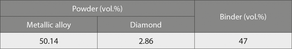
For practical purposes the optimum powder concentration in the feedstock typically is 2–3% below the CPVC. However, in this particular case, as diamond particles were being used, a slightly lower powder content was used in the feedstock, i.e. 4% below the CPVC (see Table 2).
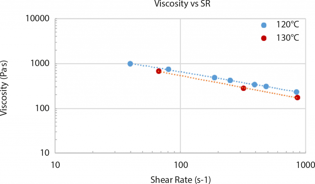
The rheological properties were evaluated using a capillary plastometer. As can be seen in Fig. 13, at 120 and 130°C., the rheological behaviour of the feedstock is adequate for the injection moulding process (with viscosities below the 1000 Pa·s considered as the highest value acceptable for the PIM process), showing viscosities in the range of 990–175 Pa·s at shear rates of 40–860 s-1.
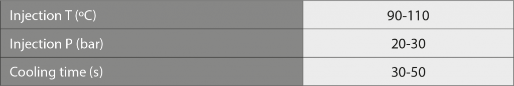
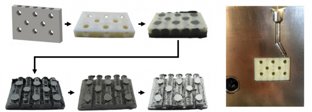
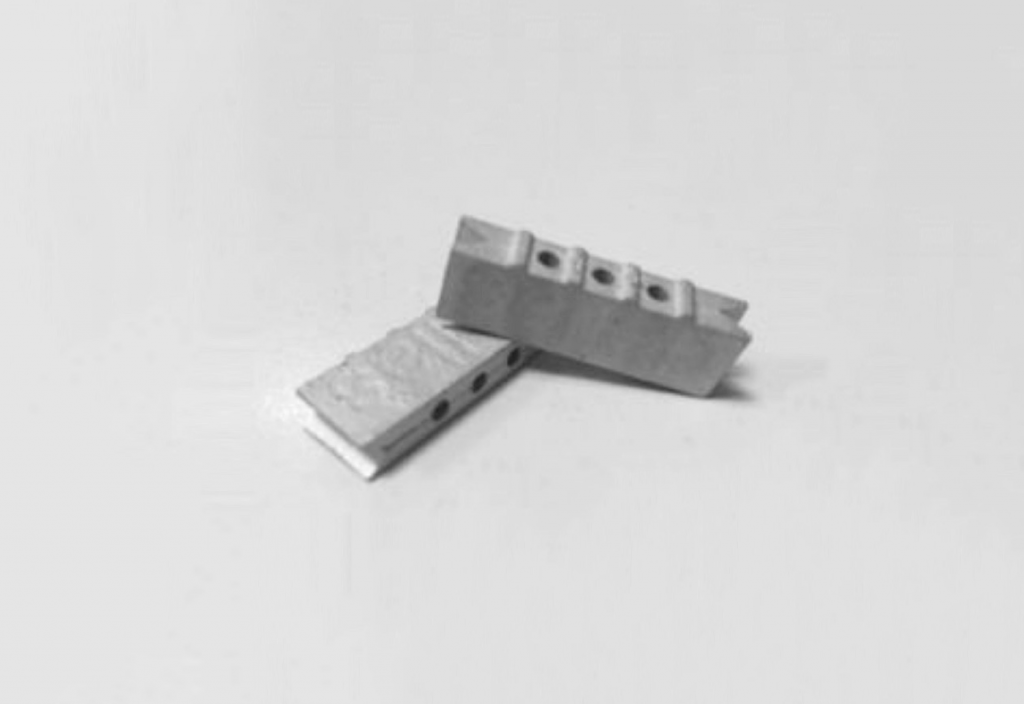
The mixtures were injection moulded to dog bone shape (ISO 2740) tensile test specimens and gang saw segments (Fig. 14) were produced. The best injection moulding parameters were defined during the moulding process optimisation so that repeatable and good quality green samples were obtained. The main parameters are listed in Table 3.
These were debound in water and thermally. The water debinding process was studied and optimised. The effects of different water temperatures and debinding times were analysed (temperatures from 20°C to 60°C and times from 1 h to 24 h). The binder removal rate strongly depended on the water temperature and the eliminated binder amount also depended on the immersion time. Although water temperatures of 40°C and 60°C gave the highest debinding rates, the debound samples showed cracks after this step, denoting too high a debinding rate. Therefore, the best compromise between debinding rate and defect-free samples was found at 30°C. After 12 h, more than 70% of the water-soluble binder fraction (PEG) was removed.
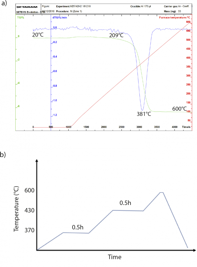
The thermal debinding cycle was designed using thermogravimetric analysis (Fig. 15). Identifying the temperature ranges at which the binder decomposes, the best profile for the thermal debinding cycle was designed. Thanks to the high binder content removed during the water debinding step, the heating rates for the thermal debinding process were increased, obtaining a substantial reduction in the time for the thermal debinding step. Brown samples, free of defects, were obtained for the sintering process.
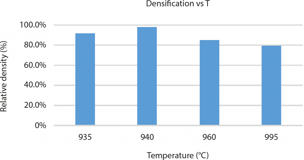
Finally, the parts were sintered under hydrogen atmosphere. The sintering process was studied so that high densities could be obtained without damaging the diamond. To this end, different sintering temperatures were tested (from 935°C to 995°C). Fig. 16 shows density as a function of the sintering temperature and identifies that the density reached a maximum at 940°C.
Preliminary mechanical evaluation of the final parts showed a hardness similar to cobalt-containing composites: conventional Co+diamond composite has a hardness of 250 HB while the new material has a hardness of 260 HB.
It was concluded that this reported work has revealed very promising results for use of the new alloy as a substitute for cobalt in diamond composites for cutting tools. However, wear and field tests still need to be performed to fully assess the properties of the new material
Author and contacts
Dr David Whittaker
Tel: +44 1902 338498
[email protected]
[1] Axel Müller-Köhn, Fraunhofer Institute for Ceramic Technologies and Systems, Germany
[email protected]
[2] Sebastian Boris Hein, Fraunhofer Fraunhofer Institute for Manufacturing Technology and Advanced Materials IFAM, Germany
[email protected]
[3] Inigo Agote, TECNALIA, Basque Research and Technology Alliance (BRTA), Spain
[email protected]
Euro PM2020 Proceedings
The full proceedings of the Euro PM2020 Virtual Congress are available to purchase from the European Powder Metallurgy Association.
www.epma.com
References
[1] 3D-printed single-use polymer moulds for prototypes and small series suitable for Powder Injection Moulding, Axel Müller-Köhn, Eric Schwarzer, Tassilo Moritz. As presented at the Euro PM2020 Virtual Congress, October 5–7, 2020, and published in the proceedings by the European Powder Metallurgy Association (EPMA).
[2] Advanced shaping possibilities for feedstock-based processes, Sebastian Boris Hein, Janne Haack, Frank Petzoldt. As presented at the Euro PM2020 Virtual Congress, October 5–7, 2020, and published in the proceedings by the European Powder Metallurgy Association (EPMA).
[3] Development of Powder Injection Moulding process of cobalt free diamond composite for cutting tool applications, I Agote, C Guraya, A Colella, E Nicolis, M Dai Prè. As presented at the Euro PM2020 Virtual Congress, October 5–7, 2020, and published in the proceedings by the European Powder Metallurgy Association (EPMA).