Winkworth: The development of custom solutions for the mixing of MIM feedstocks
Whilst many MIM companies choose to purchase commercially available 'off the shelf' feedstocks, a significant proportion continue to manufacture their own - or use both routes. Motives can range from a desire to use a proprietary binder composition for specific applications, to simple cost savings. What is critical is that in-house produced feedstocks are manufactured to the highest quality and with excellent batch-to-batch repeatability. In this article, Grant Jamieson, Managing Director of Winkworth Machinery Ltd, reviews the process of mixing, extruding and pelletising MIM feedstocks and introduces a specially-developed machine that combines these three operations. [First published in PIM International Vol. 15 No. 2, June 2021 | 10 minute read | View on Issuu | Download PDF]
The composition of feedstocks for Metal Injection Moulding applications varies according to the debinding process being used and the requirements of the material to be manufactured. For a feedstock to perform correctly, the distribution of the metal powder particles is critical. An effective mixing and distribution of the feedstock is, thus, necessary to ensure that binder material coats each individual particle.
When it comes to mixer selection for this process, a kneader blade (double arm) type Z blade mixer is often used. These mixers are renowned for gently manipulating particles throughout the mixing chamber and, after a period of time, will achieve a very homogenous distribution of particles. Z blade kneader mixers are designed for strength and to cope with the stiff phases that mixtures often go through. Each of the metal powder particles must be coated with binder, so that the feedstock can be injection moulded at a later stage and still hold its shape after ejection from the mould.
The coating of particles typically requires a binder formulation that is solid at room temperature, needs modest levels of heat to melt, and is able to coat metal powders homogeneously. The design of a mixer must, therefore, include the ability to create a consistent heat throughout the mixture. This is achieved using a thin-walled jacket on the mixing chamber; heat transfer oil is then circulated inside the jacket, conducting through into the product to achieve a homogenous temperature across the mixing chamber, with the blade design effectively distributing the heat throughout the batch.

Overview of the mixing process
The metal powders used in Metal Injection Moulding are often in the form of spherical particles approximately 20 μm in diameter; in this form, they are very heavy, but remain free-flowing. The binders used are also free-flowing. Both these dry free-flowing materials respond when heated and mixed. As the metal particles heat up, some of the heat will melt the binder. All particles will randomly respond to the transfer caused by contact with the mixing chamber and with each other during the mixing process. This heat transfer melts and liquefies the binder and allows the surface area of all the powders to be fully coated. The mixing process continues and the mixture becomes a crumb as the binder melts.
At higher temperatures, the mixture becomes a smooth dough. If the temperature is allowed to go too high, some binder ingredients may degrade, leaving the ratios of binder to metal powder affected. Therefore, temperature control throughout the mixing process is critical. Once the mixture is created, the right consistency achieved, and enough time passed, the metal feedstock becomes homogenous, with the powders evenly distributed and fully coated with the binder.
The mixture is now ready for discharge. Due to the rapid nature of cooling, which is prevalent with a metal paste due to its thermal conductivity, discharging the mixture also requires precise temperature control, often featuring some initial temperature reduction of the mass before discharge.

Creating MIM feedstock pellets
After the material has been discharged from the mixer, it needs to be processed into a suitable form. The high pressure injection moulding machines typically used for MIM are very similar to plastic injection moulding machines. Pellets are loaded into the hopper/chamber and, as they are pressed forward along the length of the machine, heat is applied to the injection barrel. The solid pellets re-melt to create an injectable material.
Once inside the injection barrel, heat transfer must occur to achieve a remelt. If particle sizes vary significantly, a risk of poor flow or bigger particles being insufficiently heated occurs and will adversely affect injecting. In order to avoid this, it is essential to achieve a consistent particle size and shape. This consistency of particle size then allows the parameters on the injection moulding machine to be established. Typically, a charge of pellets will require a determined residency period in the barrel to achieve liquifying before injecting. Once remelting has occurred the injection into the component cavity is initiated.
With tilting kneader mixers, before the pelletising of the feedstock can begin, tilt discharge to a cooling table is required, followed by a fracturing/smashing stage before passing through a granulator. This process requires additional equipment with high wear parts, while the breaking up of the block of hardened lumps can deliver random results. Quality control, productivity and cost savings are, therefore, best achieved with a hybrid mixer/extruder/pelletiser combined into one system.
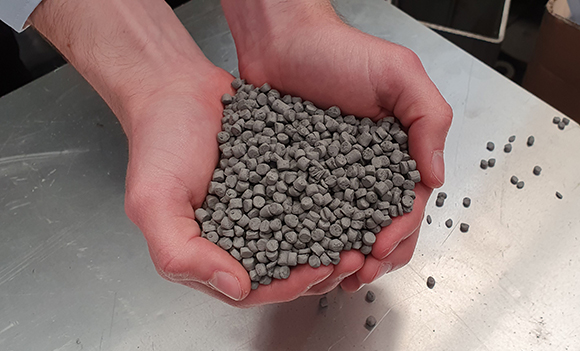
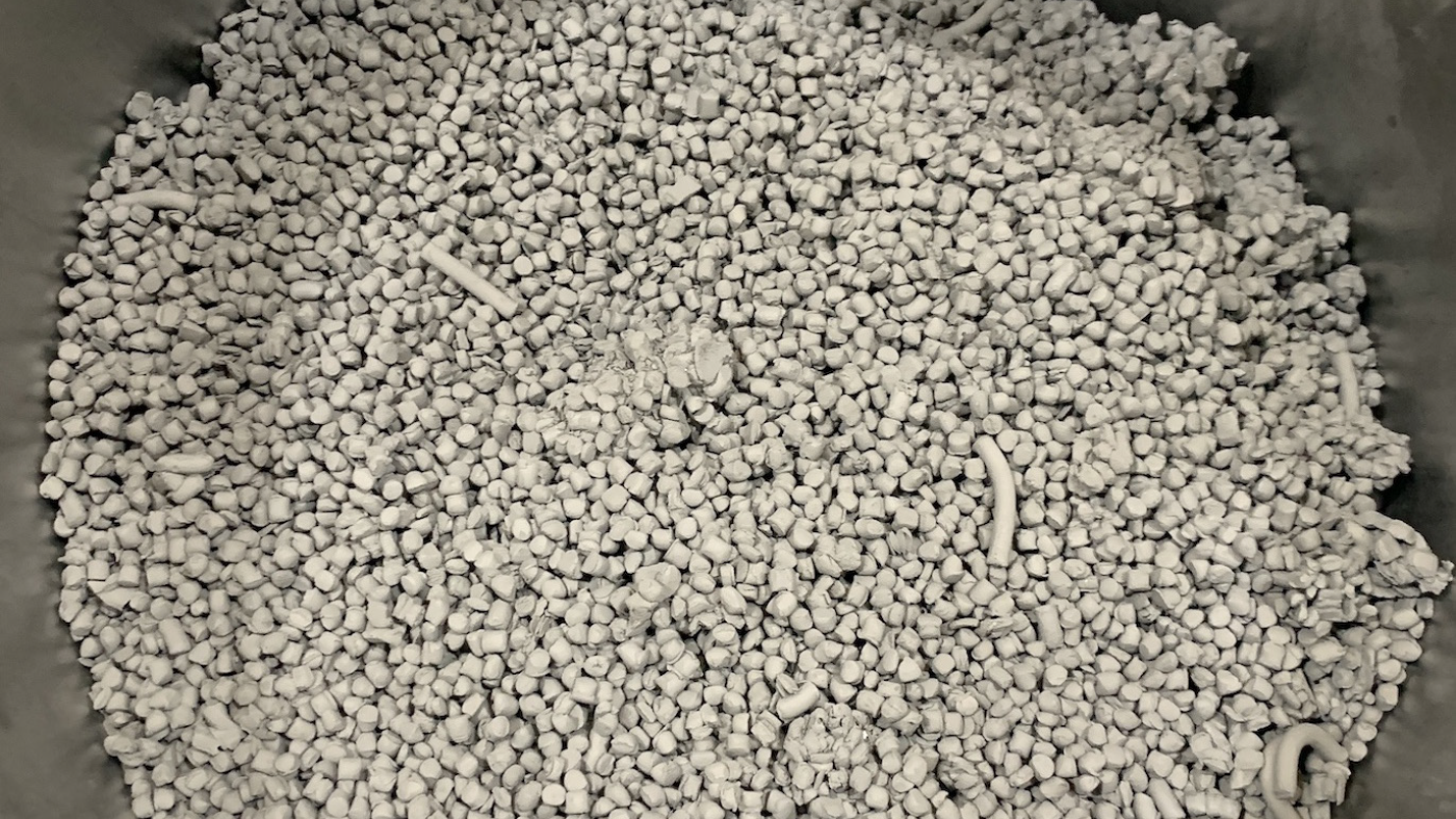
The preferred approach is to create pellets directly from the mixing process. These pellets need to be consistent in diameter, length and density, although a consistent pelletised product with such a temperature-sensitive mixture creates a number of engineering challenges. Discharging through a number of small apertures and at a constant rate is necessary and, as the product is discharged through the discharge gate or ‘die plate’, an immediate cropping or cutting of this extrudate of mixture is necessary to create pellets. Typical pellet size is normally 6-8 mm in length
he temperature sensitivity of the mixture requires extreme control of the mixing chamber environment, the discharge environment, the die-plate environment, the cutting environment and the post-cutting separation and cooling environment. These parameters must be managed with a great deal of precision and understanding of the mechanical behaviour of the mixture in order to achieve free-flowing pellets. These pellets can then be transported in sacks, barrels or through distribution pipework to feed the injection moulding machines.
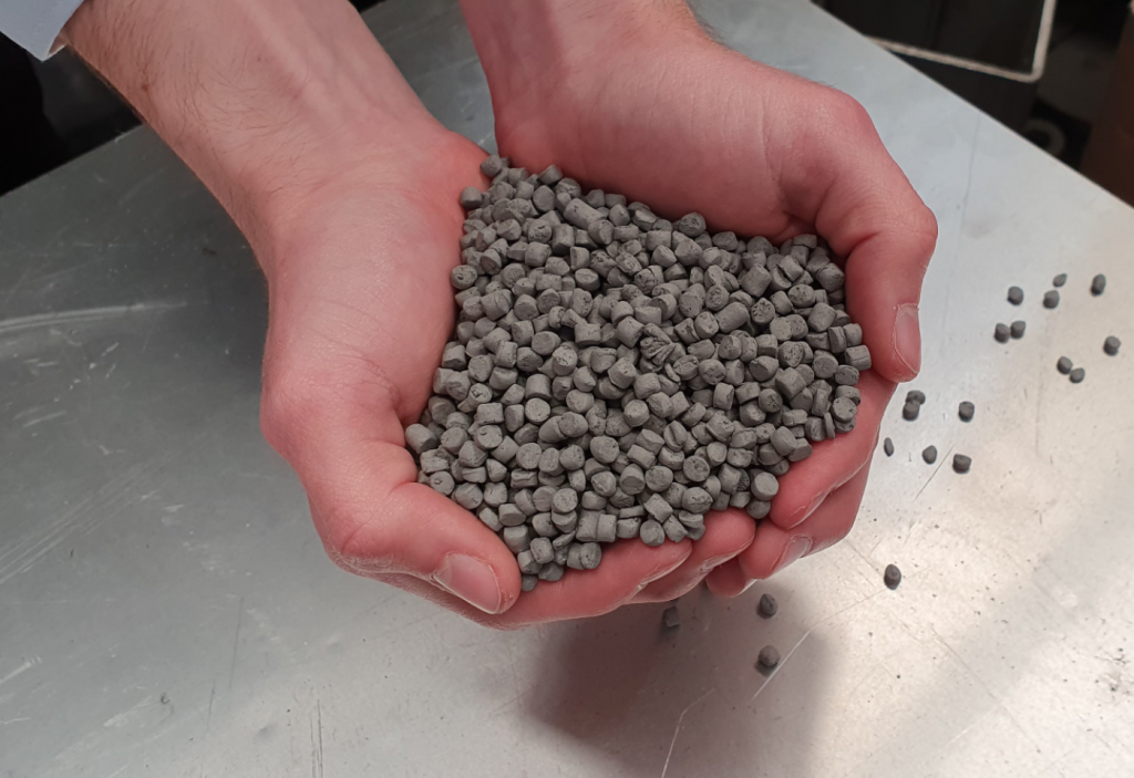
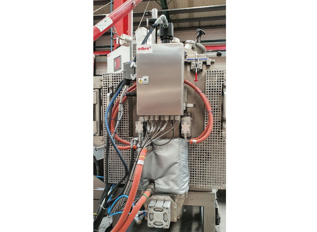
Winkworth, on instruction from one of the world’s leading MIM companies, has designed and supplied a number of machines for this purpose (Figs. 2, 3). The earliest machines had automated controls and temperature management, with discharge via extruder screw and a rotary knife against the die plate; this produced an effective result. It was later discovered, however, that a reduced heat transfer to the mixture occurred as the mixer emptied over time. Manual intervention on heating oil temperature was necessary to manage the process during discharge.
This intervention would vary according to the alloy and powder type being processed, the binder, and the ratios of the two. If the chamber is allowed to cool too much, a significant back pressure is generated during discharge as the mixture’s flowability reduces, leading to solidification. In these circumstances, a detrimental effect on the machine can occur due to the pressures created and the power applied during extrusion.

Innovation in MIM feedstock production
Winkworth has introduced a number of innovations to minimise risks of high back pressures, to increase discharge rates, avoid manual interventions during discharge, maintain separation once cropped into pellets and ensure the continued separation of pellets during cooling – particularly the avoidance of rebinding. Meeting these challenges has resulted in a two stage process:
Stage one
An extrusion discharge, unpressurised, into an integrated perpendicular chamber. This chamber is temperature-controlled using an independent heating oil recirculation system.
Stage two
A vertical hydraulic ram piston designed to uniformly press the mixture through the die plate. The die plate is electrically heated and temperature-controlled.
Once parameters for each composition are understood, reasonable expectations for mixture discharge rates are approximately 200 kg in 45 minutes. The productivity achieved in pelletising avoids the need to manage mixer chamber temperatures during discharge cycles.
The mixture for good pelletising and discharge should resemble soft, but not sticky, plasticine; more fluid than this and tearing and inconsistent pellet forms will occur. Too stiff, and pellets will be difficult to discharge; reciprocation rates will have to be managed in the knife cutter to compensate. Back pressures may also become too high and create distortion in the die plate or other mechanical arrangements.
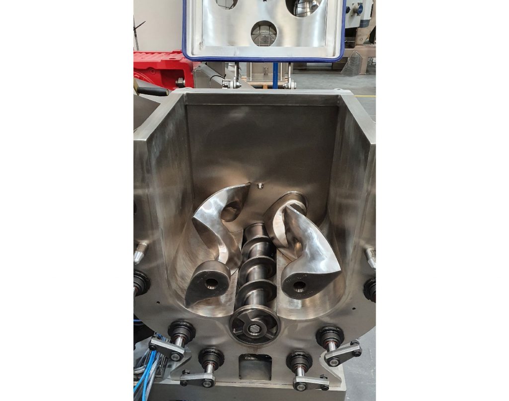
In the system developed by Winkworth (Fig. 4), a hydraulic ram, set perpendicular to the mixing chamber, uses gravity to allow for a vertical drop of the pellets once cut. A fast reciprocating multi-knife blade cuts the pellets as the mixture is extruded. The pellets then free fall to the vibrating conveyor beneath. An essential feature is for the conveyor to quickly move the pellets away from the drop zone, as discharged pellets would rebind if contact is made with others as the heat retained within them is sufficient to allow re-binding. By using a spiral cooled vibratory elevating conveyor, the pellets are suitably cooled and separation is sufficiently maintained for packaging. Additionally, a compact footprint is achieved for the installation.
The productivity gains from this method of discharge management are significant and result in much greater utilisation time in mixing and better productivity for the client.
Cleaning
In addition to mixing and pelletising challenges, on cooling, MIM feedstock becomes solid. Cleaning between batches in a cold state (room temperature) is, therefore, impractical as the material forms a cold-set structure similar to brittle toffee – and just as stuck! The design of the mixing machine must include the provision for removal of the blades, removal of the extruder screw, access to the inside of the mixing chamber and all the mixer side walls for cleaning when the machine is at an elevated temperature.
These temperatures are in excess of 100°C and would cause physical harm to operators during cleaning. Substantive personal protection equipment is necessary in the form of hot working gloves and overalls. Critically, due to the rate of temperature transfer and heat losses, the design of the machine must be suited to rapid disassembly. The machine must be openable, providing access to the chamber walls to allow scraping of hot mixture, blade removal and extruder screw removal to an adjoining bench. Blades and extruder screw can then be thoroughly accessed and cleaned whilst hot.
This has been achieved using a number of hydraulic-assisted clamps, which release on the operator’s command, and a pivoting non-drive end plate, which allows full 90° opening, thereby providing access. Blades and the extruder screw are driven by a drive stub shaft which allow tool-free removal. These are cleverly retained axially by the non-drive end plate when in operation.
Additionally, a jib crane has been designed to be mounted on the machine, facilitating the handling of these hot and relatively heavy (in excess of 20 kg each) component parts during the cleaning cycle. This attention to detail allows the client to maximise the mixing and discharge performance of the machine and allows for safe, fast and thorough cleaning when recipe changes are necessary, which helps avoid inter-batch contamination.
Conclusion
Metal Injection Moulding is increasingly being used by a diverse range of industries, and demand is undoubtedly growing. The ability to produce low-cost, high-integrity components will continue to drive this technology. Developments in mixing and discharge management, such as those described above, can make a significant contribution to the future adoption of MIM approaches. Similar approaches can, of course, be utilised in Ceramic Injection Moulding (CIM) and other Powder Injection Moulding (PIM) applications.
Author
Grant Jamieson
Managing Director
Winkworth Machinery Ltd
Mixer House
Stroudley Rd
Basingstoke RG24 8FW
United Kingdom
Tel: +44 1256 305 600
[email protected]
www.mixer.co.uk