


The maths in the magic: Calculating the sintering shrinkage of MIM parts
Newcomers to Metal Injection Moulding never cease to be amazed when they see that green parts uniformly shrink during debinding and sintering into a finished part. This calculated shrinkage, which is what enables products to conform to an engineer’s blueprints, can appear pretty magical. It is, of course, simply a matter of mathematical calculation. In this article, Dr Chiou Yau Hung (Dr Q) and James Chao, from You neeD Technology Office, Taiwan, encourage you not be scared off by the mathematics and discover the calculations at the heart of MIM. [First published in PIM International Vol. 16 No. 2, June 2022 | 10 minute read | View on Issuu | Download PDF]
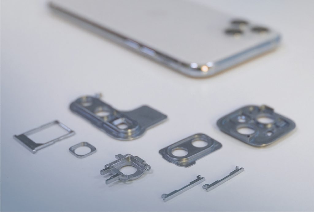
In 1972, Parmatech applied for the first patent for Metal Injection Moulding. From these beginnings, no one could have imagined the MIM process as the indispensable metal parts manufacturing method it has become fifty years later, without which many of the modern products we rely on would either be impossible to produce, or quite different. What was originally a process reserved for use with refractory materials and hard-to-process alloys must now meet demands for millions of parts per day for applications in computers, communications and consumer electronics (3C), automotive, aerospace, medical and far beyond.
Anyone new to MIM technology might marvel at the use of plastic injection moulding machines to form these metal parts in industrial quantities. They might be especially amazed when they see that the green parts, after debinding and sintering, can be uniformly shrunk into a finished part. This calculated shrinkage, which allows products to conform to an engineer’s blueprints, can appear pretty magical.
In this article, please follow me as I show you how this magic MIM shrinkage is calculated with a simple mathematical model. Don’t be scared off by the mathematics; here, we will only use simple calculations, which can be undertaken by anyone in a Microsoft Excel sheet. Readers must note that this model has been created to reflect the ideal manufacturing situation and variations in powder size suitability, equipment, etc. must be considered when replicating these calculations.

Archimedes formula for density
To start, we need to understand the Archimedes formula for density:
![[eqn. 1]](http://www.pim-international.com/wp-content/uploads/sites/2/2023/09/Equation-1-1-1024x298.jpg)
Here, ρ = the density of a material, M = the mass of a material, and V = the volume of a material. 1~n∈R is the number of different materials present – when there are too many types of material, a grouping calculation reduction can be used to merge the volume or weight of several different materials. Finally, T = temperature (°C, °F, or K). 15-30°C are preferred for testing
We then have to understand the volume of a cuboid:
![[eqn. 2]](http://www.pim-international.com/wp-content/uploads/sites/2/2023/09/Equation-2-1-1024x122.jpg)
x, y, z = the edge length of the cube in each direction. When the object is a cube, its volume is equal to a simplified calculation method of this model when x = y = z and the volume of the cube of equilateral length = x3
Defining of cavity size: Oversize Shrinkage Factor (OSF)
We now need to understand cavity size versus the size of the final sintered part:
![[eqn. 3]](http://www.pim-international.com/wp-content/uploads/sites/2/2023/09/Equation-3-1-1024x311.jpg)
Here, S = size of the part after sintering. C = cavity of the part. The green part, after injection, will naturally be able to be removed from the cavity due to the shrinkage of the MIM feedstock. Therefore, if the design value of OSF is 1.165, it is natural to import equation (3) to convert the size of the cavity.
When assuming that the shrinkage of the raw blank is negligible when it is removed from the mould, equation [4] can be changed to:
![[eqn. 4]](http://www.pim-international.com/wp-content/uploads/sites/2/2023/09/Equation-4-1-1024x255.jpg)
Here, G = green part. If metal powders and binders are very uniformly dispersed in the feedstock, we can accept xG = xC. In general, xG < xC is correct. Green parts can be detached from the cavity after injection moulding. In fact, a green part will still encounter some shrinkage after the feedstock cools. My suggestion is to use xG = xC as a simple calculation
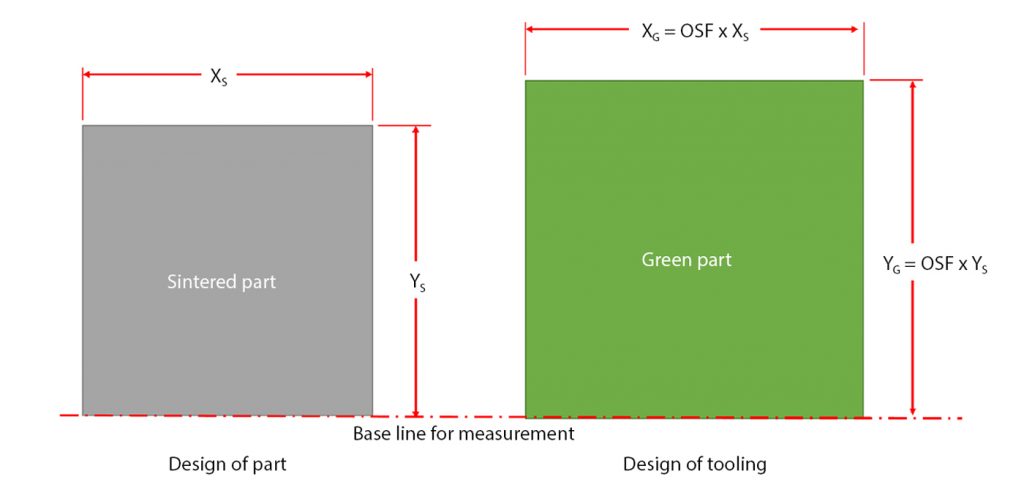
According to the assumptions of Equation [4], the small shrinkage of the green part after it is removed from the cavity is ignored when the injection process is finished. The relationship between the design dimensions of the MIM part and tooling is shown in Fig. 2.

Volume ratio of powders and binders
The ratio of powders and binders of MIM green parts can be estimated, based on the OSF values we have selected. We still import equation [4] as a cube part. At the same time, the following assumptions must be noted, when performing the actual MIM process:
Metal powder size
Metal powder particle size for MIM is < 45 um and the optimal particle size range is d10 > 2 um, d50 = 9.8 um, and d90 < 22 um.
Powder/binder separation
MIM powders and binders are evenly distributed and uniform after injection moulding. When we observe black marks on, or under, the surface of a green part, that location will sink after sintering. The main reason is that the high shear force of the injection press or cavity thickness change leads to the separation of powders and binders. The black mark phenomenon is observed where there is more binder and this causes the affected areas to sink
Debinding and sintering conditions
The temperature of debinding and sintering is uniform and atmospheric pressure and flow is stable. This means selecting a high-performance sintering furnace with automated program controls
Distortion during sintering
Dimensional changes in the sintered part, due to phase changes of material in the sintering process, are ignored. In practice, the effects of material phase changes can be corrected in post-processing procedures
Metal evaporation during sintering
Metal evaporation losses during the metal sintering process are ignored
Equation (3) and (4) can be changed into:
![[eqn. 5]](http://www.pim-international.com/wp-content/uploads/sites/2/2023/09/Equation-5-1-1024x266.jpg)
Therefore, when we have a requirement of OSF = 1.165, we use a cube to simplify our calculation and, when the cube edge length = 10 (length unit) = xc, xs= 10/1.165 = 8.5837.
Because powder volume will become metal volume= (xs)3 = (8.5837)3 = 632.4462 = Vs (Volume of sintered part) can be calculated. The volume of metal powders and binders should be equal to the cavity volume.
So, we can calculate the volume of binder from VB = Vc-Vs = (10)3 – (8.5837)3 = 1000 – 632.4462 = 367.5538 (volume units).
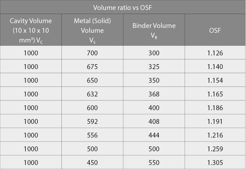
When OSF = 1.165, metal powder volume:binder volume = 632.4464:367.5538 = 63.2%:36.8%. In the MIM process, the defined OSF will depend on the particle size, material, and geometry of powder. For example, 3XX series stainless steels and 17-4PH stainless steel will use OSF = 1.165; CIP and low-alloy series will use OSF = 1.191 or 1.216; and tungsten alloys (W-Ni-Cu and Wu-Ni-Fe) will use OSF = 1.259. Where the OSF is bigger, powder loading will be lower. Table 1 shows a list of metal powder/binder ratios usually used in calculating the OSF. After sintering, the binders will be burnt out, resulting in VB = 0.
Weight ratio of powders and binders
Actual factory operations do not perform volumetric measurements of powders and binders, so individual densities of substances must be imported to assist in the calculation to speed up the operation. Therefore, here it is assumed that the stainless steel is 17-4PH material (15 kg powders) and that the binders are seven different types comprising Polyformaldehyde (POM), Polypropylene (PP), High Density Polyethylene (HDPE), Ethylene Vinyl Acetate (EVA), Paraffin Wax (PW), Stearic Acid (SA), and 1010 (BASF antioxidants). The individual binder weight ratios are: 88: 2.5: 2.5: 1: 1: 4: 1. We calculated, when OSF = 1.165, each binder weight. The third decimal place, following the decimal point, is calculated using the 4th rounding and 5 system method.
Now, we start the calculation. The calculation program uses a spreadsheet to perform a more factory-appropriate application.
Looking at the appropriate ASTM table, we know that the density of 17-4PH is 7.85 g/cm3; the weight of the 17-4PH stainless steel metal powder in this project is 15,000 g = 15 kg.
According to OSF = 1.165, we first calculate the volume ratio of binders. We know the metal powder volume: binder volume = V17-4: VBinder = 63.2:36.8; So, V17-4= M17-4/ρ17-4 = 15,000 g/ (7.85 g/cm3) = 1,910.828 cm3. Then, we can get VBinder = (1,910.828 cm3/63.2) x 36.8 = 1,112.634 (cm3)

Assuming that binder materials are not vapourised during a mixing process, we know how to obtain the volume of the total binder = 1,112.634 (cm3). According to an individual weight ratios of the binder (which need to be defined and designed from our recipe) = POM: PP: HDP:EVA: PW : SA: 1010= 88: 2.5: 2.5: 1:1: 4: 1.
Each binder density is: POM = 1.4 (g/cm3); PP = 1 (g/cm3); HDPE = 1 (g/cm3) = EVA ; PW = SA = 1010 = 0.95 (g/cm3). All of the data have now been simplified. We can calculate the density value of the binder according to the design level of 100 g.
The individual volume of the binder should be VPOM = 88/1.4 = 62.857 (cm3); VPP = 2.5/1 = 2.5 (cm3); VHDPE = 2.5/1 = 2.5 (cm3); VEVA = 1/1 = 1; VPW=1/0.95 = 1.053 (cm3); VSA = 4/0.95 = 4.211 (cm3); VSA = 1/0.95 = 1.053 (cm3). Volume of total binder = 2.857 + 2.5 + 2.5 + 1 + 1.053 + 4.211 + 1.053 = 74.12 (cm3), and density of total binder VBinder 100 g = 100 g / 74.174 cm3 = 1.349 g/cm3. Therefore, when the overall weight of the binder must be WBinder = 1,112.634 cm3 x 1.349 g/cm3 = 1,501.119 g
- Metal weight:Binder weight = 1,5000 g:1,501.119 g = 90.9:9.1
- Each binder constituent weight is: MPOM= 1,501.119/(88/100) = 1321 (g); MPP = 1,501.119/(2.5/100) = 37.5 (g) =MHDPE; MEVA = 1,501.119/(1/100); = 15 g MPW = 1,501.119/(1/100) = 15 (g) = M1010; MSA = 1501.119/(4/100) = 60 (g).
Fig. 3 is a screenshot of a table taken from Microsoft Excel. Readers can make this table by associating the results of the upper number calculations themselves.

Repeated verification and correction
Some problems in the calculation process include how do we set up decimal points? Some readers may want to include more digits, thinking that the density of the material should be as accurate as possible. This is a divisive point for engineering applications and scientific research, but the second decimal place of the data is enough to satisfy engineering applications.
Another question is which value is correct for the theoretical density of a material? Or do you refer to the historical results of sintering in your factory? A helpful practice of the Japanese Powder Metallurgy Association (JPMA) is the publishing of a product quality report for all Japanese members every year. This can be used to gather average density and dimension statistics for MIM products from various materials. All members can refer to this as a benchmark for calculation.
In a production line, weight and dimension are closely related. In fact, while the dimensions of a green part may not reflect the dimensions of the final sintered part, the state of tooling and cavities can be understood through the measurement process. I would still emphasise the three elements of the Archimedes formula: the density, weight, and size of the green, debound, and sintered parts, as well as the overall appearance of the part. These are all quality factors that are indispensable to MIM. Though it is relatively simple, this mathematical model for shrinkage is subject to constant verification and correction. The numbers presented are not static and require careful observation, minute analysis, research, and testing by practitioners.
Conclusion
I do not know whether those readers, who do not like mathematics, have been scared away, or have skimmed the above formulae to skip to the lessons we take from them, but, in truth, it is only in practice that we can truly appreciate the meaning of this mathematical model. Since the formulae for multi-material (metal, with element powder and more binders added to the recipe) combinations are more complicated, we hope that you can use the table calculation as much as possible to ease your own calculations. In future, I will discuss how to rescue feedstock that shrinks too little (sintered part dimension is too large) or too much (sintered part dimension is too small). As well as using the compensation method for identifying unequal shrinkage after moulding, these need to be based on the mathematical model in this article. We will wait until a future issue to present these calculations.
Authors
Dr Q (Y H Chiou)
You neeD Technical Office
[email protected]
[email protected]
James (Y D Chao)
You neeD Technical Office
[email protected]


