Sinter-based AM & MIM at the 21st Plansee Seminar: Cemented carbide and tungsten heavy alloy developments
The 21st Plansee Seminar, held in June 2025, provided deep insight into the evolving landscape of sinter-based Additive Manufacturing (AM) for cemented carbides and tungsten heavy alloys. Presentations explored Binder Jetting, Material Extrusion, Direct Ink Writing, and other emerging techniques, with a focus on microstructural control, process–property relationships, and feedstock optimisation. While Binder Jetting remains influential, alternative approaches are gaining traction for finer powders and complex geometries. This article, authored by Bernard North, examines the key technical findings and perspectives shared at the event. [First published in Powder Injection Moulding International Vol. 19 No. 3, Autumn 2025 | 10 minute read | View on Issuu | Download PDF]
The Plansee Seminars represent a long-standing tradition within the refractory metals and hard materials community [1]. In 1952, Paul Schwarzkopf of the Plansee Group initiated the seminar series to foster the exchange of ideas and knowledge among industry professionals – in his memorable phrase: “To sinter the participants to a dense powder metals community.” Initially held every three years and later every four, the author has been fortunate to have attended at least six of the week-long seminars, including the most recent three.
Originally scheduled for 2021, the 20th Plansee Seminar was postponed to 2022 due to COVID-19, with reports published in PM Review [2], PIM International [3], and Metal Additive Manufacturing magazines [4]. The 21st Seminar was scheduled for June 2025, just three years after the previous event, to align with other conferences in these fields.

This article focuses on MIM and sinter-based AM contributions at the 21st Plansee Seminar. Further coverage of conventional PM appears in the Autumn 2025 issue of Metal Powder Technology [5], with additional reporting on PBF and other direct AM processes set to appear in Metal Additive Manufacturing [6].
MIM and metal AM at the Plansee Seminars
Metal Injection Moulding (MIM) is a well-established Powder Metallurgy (PM) technology with some use in cemented carbides and refractory metals. Most developments now are, however, of a proprietary nature, and, as such, the technology has not featured strongly in oral presentations or posters in recent Plansee Seminars.
Additive Manufacturing, in contrast, embraces several technologies with differing development timescales, some of them relatively recent, and these featured strongly at this year’s event. Analysis of the 19th and 20th Seminar abstracts (Fig. 2) shows notable growth in AM-related presentations and posters. AM accounted for ~12% of the total content at this year’s Plansee Seminar.
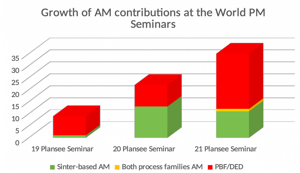
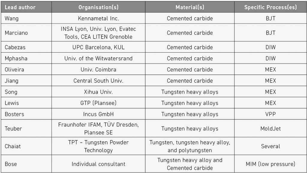
Table 1 lists the AM presentations by material category. There was a roughly even split between cemented carbides and heavy tungsten alloys (also known as heavy metals). Notably, there were no presentations on refractory metals or high-temperature superalloys using sinter-based AM processes.
The presentations covered a variety of sinter-based AM processes, including Material Extrusion (MEX), Binder Jetting (BJT), direct ink writing (DIW – a form of MEX), Vat Photopolymerisation (VPP), also known as lithography-based metal manufacturing (LMM), and the MoldJet process. There were, in total, a similar number of presentations on these AM techniques as were given at the 20th Seminar in 2022 [4].
In the latest seminar, however, there were fewer cemented carbide and more heavy metal studies, and a slight shift from BJT towards slurry (‘ink’) or paste-based techniques. The following sections summarise the key presentations in detail.
Binder Jetting of cemented carbides
Process comparisons
![Fig. 3 Technology assessment ratings for the seven sinter-based processes across the five main dimensions [7]](http://www.pim-international.com/wp-content/uploads/sites/2/2025/09/fig-03-685x1024.jpg)
A presentation [7] by Zhuqing Wang et al., introduced by Dominik Schmidt of Kennametal, opened by discussing the relative strengths of different sinter-based AM techniques based on specific factors, namely cost of operations, investment required, technical maturity, geometry capability, and material quality. The researchers used radar charts (Fig. 3) to compare different sinter-based AM systems processing cemented carbides.

A Binder Jetting system enabling control over binder saturation, droplet size and velocity produced parts with superior surface finish (Fig. 4) and higher sintered strength. This improvement was attributed to enhanced powder–binder interaction, although the strength of a 10 wt.% Co sub micron grade commonly used for solid round tooling remained ~15% lower than that of conventionally processed material due to the presence of cobalt pools and coarse grains.
![Fig. 4 Custom test parts built using Binder Jetting machines: (a) fixed droplet parameters; (b) adjustable droplet size and velocity, showing improved surface finish and resolution [7]](http://www.pim-international.com/wp-content/uploads/sites/2/2025/09/fig-04-1024x547.jpg)
Metalcutting testing of a solid carbide reamer showed that the BJT product performed similarly to, or better than, a conventionally manufactured control. The BJT process also has advantages in terms of near-net shaping and geometrical freedom.
Process–property relationships
Erwan Marciano of INSA Lyon presented work [8] studying the effect of BJT binder saturation and powder layer thickness on the green density, four-point bend strength, and associated fracture surfaces of a WC 12% Co powder with a mean particle size (d50) of 11.5 μm. Binder saturation levels between 45-75% were tested, and powder layer thickness was varied between 60-120 μm at a 60% binder saturation level. Green density varied little with binder saturation, but was highest (~42% theoretical) for thinner powder layers. In contrast, green strength was highly sensitive to both binder saturation and layer thickness (Fig. 5).
![Fig. 5 (a) Effect of binder saturation (layer thickness 60 µm) on part rupture strength; (b) Effect of layer thickness (binder saturation 60%) on part rupture strength. Numbers adjacent to data points indicate the number of samples tested for each point [8]](http://www.pim-international.com/wp-content/uploads/sites/2/2025/09/fig-05-1024x341.jpg)
SEM images of the green fracture surfaces (Fig. 6) clearly show the individual layers and inter-layer porosity at the highest thickness levels, suggesting that thicker powder layers are not uniformly compressed during the rolling stage prior to jetting, and/or that thick layers are not fully impregnated with binder solution. The authors plan to investigate the effect of binder setting time.
![Fig. 6 SEM images of fracture surfaces for different layer thicknesses using WC702 powder: (a) 60 µm, (b) 80 µm, (c) 100 µm, (d) 120 µm. For each case: (I) macroscopic image, (II) ×100 magnification, (III) ×500 magnification [8]](http://www.pim-international.com/wp-content/uploads/sites/2/2025/09/fig-06-922x1024.jpg)
Direct ink writing of cemented carbides
Feedstock development
Laura Cabezas presented work [9] by UPC Barcelona and KU Leuven in which parameter variation in DIW of a moderately coarse-grained (3.1 mean grain size) WC 12 wt.% Co was investigated. The goal of the study was to optimise green and sintered product quality. A 40.8 vol.% powder was processed into an ‘ink’ with an anionic dispersant, antioxidant, hydrogel, and distilled water constituents.
Experiments were conducted using a fixed 0.25 mm nozzle diameter, a 90° infill orientation sequence, and 600 Pa extrusion pressure, while the feed rate, layer thickness, and overlapping parameters were varied. Orthogonal samples were dried for seven days in a humidity-controlled environment. Some were examined in the green state by SEM to identify build defects (Fig. 7), while others were debound and vacuum sintered.
![Fig. 7 Cross-sectional SEM images of gradient samples in the green state, built with filament overlaps of (a) 2.0 mm, (b) 1.9 mm, (c) 1.8 mm, and (d) 1.7 mm [9]](http://www.pim-international.com/wp-content/uploads/sites/2/2025/09/fig-07-1024x215.jpg)
The work determined that the best parameter set was a 10 mm/s feed rate, 0.18 mm filament overlap, and 0.19 mm layer height. Microstructural analysis, Vickers hardness testing, single-edge notched beam testing (with notches introduced by pulsed laser), and transverse rupture testing indicated good, uniform microstructures and hardness–toughness combinations typical of conventionally processed material. Strength levels were comparable to conventional controls, although the lower Weibull modulus (3.6) suggested the presence of large flaws remaining after vacuum sintering.

Powder blend optimisation
Nthape Percyval Mphasha presented cemented carbide DIW [10] work done with the University of the Witwatersrand, Nelson Mandela University, and KU Leuven co-authors. This study differs primarily insofar as the raw materials comprised ~1 μm grain size WC previously plasma spheroidised into ~20 μm particles mixed with finer Mo powder to produce a WC-8.4Co-3.6Mo (wt.%) powder blend. Inks were made with a dispersant and hydrogel in distilled water at four different solids loadings.
Rheological testing confirmed the desired shear-thinning behaviour, and that shear stress and viscosity were highly dependent on the solids loading (Fig. 8). Orthogonal parts were produced with a 250 μm diameter nozzle, 20mm/s build speed, 180 μm line spacing with a 25% lateral offset and unidirectional raster, while pressure was varied between 100-400 kPa, and layer thickness from 200-250 μm.
![Fig. 8 (a) Shear stress and (b) apparent viscosity of the investigated pastes prepared using 25wt% Pluronic F-127 stock solution, as a function of applied shear rate [10]](http://www.pim-international.com/wp-content/uploads/sites/2/2025/09/fig-08-1024x329.jpg)
Test pieces were dried under controlled humidity, then debound and vacuum sintered. Microstructural analysis showed better results from higher solids loading (92.4 wt.%), but with some binder pooling and uneven grain size distributions attributable to the starting powder mixture. Further improvements in microstructure, sintered density, and crack reduction were achieved by reducing the strand width and layer thickness to 28 μm and 19 μm, respectively.
Material Extrusion of cemented carbides
![Fig. 9 Topography of the surface of green WC-Co, produced by MEX, with a box created by laser ablation [11]](http://www.pim-international.com/wp-content/uploads/sites/2/2025/09/fig-09-1024x680.jpg)
Gonçalo Oliveira of the University of Coimbra presented work done in collaboration with Palbit [11] on improving the surface roughness – a problem in practice for many applications – of WC-10 wt.% Co fabricated by Material Extrusion. Orthogonal test pieces were surface treated in the green condition with a ytterbium-fibre laser under different condition sets, and the green surfaces characterised by optical microscopy, contact and non-contact profilometry (Fig. 9), and SEM.
The processing of green parts, rather than sintered, is preferred due to the lower energy consumption required and the avoidance of undesirable surface effects after sintering. The work demonstrated that a halving of surface roughness was readily achievable.
A poster authored by Fengze Jiang and colleagues at Central South University, Changsha, China [12] described a very detailed study in which a MEX binder composition and associated processing were developed. The processing steps included a two-step aqueous solvent debinding followed by thermal debinding for a WC-8 weight% Co material with a mean particle size of 1.94 μm.
Five different mixes were made, each with a fixed 45 vol.% solids, and fixed amounts of stearic acid and polyethylene wax, but varying levels of polyethylene glycol (PEG), polyvinyl butyral (PVB), and high-density polyethylene (HDPE). The mixes were extruded at 165°C through a 0.5 mm diameter nozzle at a build speed of 35 mm/s at a 100°C bed temperature. The mixes were used to form orthogonal disc-shaped test pieces as well as complex demonstration samples.
In-depth analysis showed that aqueous solvent debinding followed first order diffusion kinetics with the rate dependent on water temperature and binder composition (Fig. 10), while thermogravimetric analysis during thermal debinding showed peaks in weight loss rates at 250°C, 360°C, and 450°C corresponding to removal of PVB, PEG, and HDPE respectively, while FTIR (Fourier Transform InfraRed Spectroscopy) indicated multiple decomposition products.
![Fig. 10 (a) PEG extraction from green bodies additively manufactured using different feedstocks at 45°C; (b) PEG extraction rate from a sample manufactured with PEG50B15 at varying temperatures [12]](http://www.pim-international.com/wp-content/uploads/sites/2/2025/09/fig-10-1024x349.jpg)
The amount of carbon retained after thermal debinding depends on both the gas composition and the prior binder composition (Fig. 11). These factors must be considered when targeting the desired final composition and properties.
![Fig. 11 (a) Total carbon content of brown bodies built with P50B15 under different thermal debinding atmospheres; (b) Total carbon content of brown bodies built with different feedstocks after thermal debinding in N2/H2 atmosphere [12]](http://www.pim-international.com/wp-content/uploads/sites/2/2025/09/fig-11-1024x366.jpg)
Finally, the quality of sintered pieces indicated an optimal binder composition of (in vol.%): 50 PEG, 15 PVB, 25 HDPE, 10 (stearic acid + polyethylene wax). Sintered samples have good microstructures and shape retention, and transverse rupture strengths ~1.7 GPa, closely approaching those of conventional controls.
Material Extrusion of tungsten heavy alloys
Jiupeng Song and colleagues at Xihua University presented a poster [13] on the development of a binder system and process for Fused Deposition Modelling (FDM) or Fused Filament Fabrication (FFF) of a 93W-4.9Ni-2.1Fe (wt.%) heavy metal, followed by MEX fabrication of parts. A 50 vol.% solids loading of the WNiFe powder mixture (mean particle size ~3.5 μm) was made by intimate, high shear mixing at 185°C with an organics mixture of (by weight): 90% polyoxymethylene, 5% polypropylene, 4% rubber and 1% lubricant, and was then twin screw extruded into 1.75 mm filament, which could be wound onto a spool.
Rheometry confirmed that the extrusion mix exhibited the desired shear-thinning behaviour. Orthogonal and hollow cylindrical test pieces (Fig. 12) were made by the MEX AM process using a climate box temperature of 90°C, a 0.6 mm diameter nozzle, an extrusion temperature of 200°C, a filling speed of 90 mm/s, and a layer thickness of 0.15 mm. As-built parts were catalytic debound in oxalic acid at 130°C and then sintered in H2 at 1,460°C, followed by solution treatment at 1,100°C. Linear shrinkage was ~24.6% and sintered density 17.65 g/cm3, a little over 98% of theoretical.
![Fig. 12 (a) Sintered and heat-treated cube; (b) sintered thin-walled cylinder; (c) sintered hyperbolic cylinder [13]](http://www.pim-international.com/wp-content/uploads/sites/2/2025/09/fig-12-1024x267.jpg)
Tensile and Charpy impact pieces were machined and tested against conventionally processed controls of the same alloy; ultimate tensile strengths were similar to controls, but the AM samples were a little lower in hardness and had only about half the ductility and impact strength of the conventionally processed samples, which could be explained by the remanent porosity.
A poster [14] authored by Kara Lewis of Global Tungsten & Powders Corp, also described the development and initial optimisation of a binder system for MEX of a W-Fe-Ni heavy alloy. Paraffin wax, stearic acid, and PEG, which all melt in the 50°C-70°C range, were blended at the 5, 10, and 20 wt.% levels (total binder) with the metal powder in the temperature range 120-200°C by three different methods, the most effective being planetary mixing, although results indicated the need for further optimisation to produce a more intimate powder/binder blend.
The 10 wt.% binder candidate was selected for further work because 5% was clearly inadequate to fully coat the metal powders, while 20% is unnecessarily high. Thermogravimetric analysis indicated the binder is removed between 200-400°C, which is desirable given that W oxidation is prevalent at ~500°C. Rheological testing showed the desirable shear-thinning behaviour. The plunger-based machine proved too simplistic for producing parts, primarily due to the lack of a heated nozzle, which led to clogging.
Lithography-based metal manufacturing of tungsten heavy alloys
Lithography-based Metal Manufacturing (LMM) of a W97.1-Fe0.9-Ni1.9 wt.%, 5.5 μm mean particle size heavy metal powder was the subject of a poster [15] by Johannes Bosters and co-authors from Incus GmbH and Plansee SE.
LMM is typically limited by fine particles of dense metals, which inhibit light ingress into the suspension being selectively cured to produce parts, but this was overcome in this study by two techniques: near UV laser-based (SLA) and a projector-based approach (DLP), which increases intensity while reducing pixel size. Suspensions with between 48-53 vol.% solids were made with proprietary binder systems, and test parts built (Fig. 13) in a bed held at ~17°C using a 15 μm layer height and scan speed of 20 mm/s. Parts were dried at 120°C for 18 hours, debound in H2 up to 800°C, sintered at 1,500–1,550°C in H2, and finally vacuum heat treated.
![Fig. 13 Comparison of B1 and B2 for the SLA and DLP processes [15]](http://www.pim-international.com/wp-content/uploads/sites/2/2025/09/fig-13-1024x750.jpg)
Tests showed that the powder/binder suspension was stable for at least a year and that up to 100% of the recycling of ‘unscanned’ suspension could be done with no effect on quality. Zero porosity, 100% dense sintered parts were obtained by either process over the vol.% solids range tested, but for the best part surface quality, 50% was chosen for further work. Optimal binder selection was a function of whether the SLA or DLP process was used; in either case, UTS (ultimate tensile strength) levels of ~1,040 MPa and ductility ~18% were achieved, which properties, furthermore, were the same in the x and y building directions.
Mould slurry deposition: complex part potential
![Fig. 14 Schematic overview of the applicator system used in the MoldJet process, showing the steps involved in slurry processing and mould cavity filling [16]](http://www.pim-international.com/wp-content/uploads/sites/2/2025/09/fig-14-1024x538.jpg)
Mould slurry deposition is an AM process in which multiple inkjet build heads form a negative of the part layer being produced, and the cavity is filled with a paste loaded with metal powder (Fig. 14). After drying and curing, the process is repeated many times to form parts.
Robert Teuber and co-authors from the IFAM Fraunhofer Institute, Dresden; Dresden University of Technology, and Plansee SE described work [16] processing a 97W-2Ni-1Fe (wt.%), 5.5 μm mean particle size using the MoldJet platform from Tritone. The study resulted in a 93.76 wt.% metal powder mixture in aqueous suspension with no less than six agents in solution to achieve the necessary dispersant, defoaming, rheology modification, wetting, and oxidation inhibition requirements.
The AM machine used for the process had six platforms producing parts simultaneously; each featured in-process camera inspection after each layer deposition, and each layer was dried and cured first in warm air and then in vacuum. Green parts were first heated to 85°C to remove the polymeric wax moulds, then debound at 800°C in H2, sintered at 1,500–1,550°C in H2, and finally vacuum heat treated.
Densities close to theoretical were obtained; however, elongated pores resulted in wide scatter in strength and ductility values when tested parallel to the z direction, so some further optimisation is needed, although the process shows good capabilities for complex part manufacturing (Fig. 15).
![Fig. 15 Demonstrator part featuring a complex internal cooling channel structure shown after build (left, middle) and after sintering and machining (right) [17]](http://www.pim-international.com/wp-content/uploads/sites/2/2025/09/fig-15-1024x516.jpg)
Laminated object manufacturing of tungsten alloys
A poster by Dov Chaiat of TPT – Tungsten Powder Technology [17] reviewed different AM processes for tungsten refractory metal and tungsten heavy alloys, including BJT and LMM of the latter.
![Fig. 16 Bulk Laminated Hybrid structure [17]](http://www.pim-international.com/wp-content/uploads/sites/2/2025/09/fig-16.jpg)
A particularly notable contribution was the description of the Laminated Object Manufacturing (LOM) process in which heavy alloy powders are intimately blended with a thermoplastic polymer, plasticiser, and dispersant in a suitable solvent and then a tape casting/doctor blade process is used to make a green ‘sheet’ 0.1-1 mm thick. Multiple layers of sheet are stacked together, cut to size (allowing for 15-20% linear shrinkage) and then debound at up to 600°C prior to sintering in a H2 and/or vacuum environment.
As with other AM processes, some post-processing may be required. An intriguing development related to this work is the creation of hybrid structures with alternating interlayers of compatible materials, offering the potential for tailored functionality (Fig. 16).
Polytungsten via Fused Pellet Fabrication
![Fig. 17 (a) PA6-W microstructure; (b) Poly–tungsten FPF; (c) printed PA6-W sample (density: 12 g/cm3) [17]](http://www.pim-international.com/wp-content/uploads/sites/2/2025/09/fig-17-1024x326.jpg)
Chaiat’s poster also discussed polytungsten, which is basically a polymer with a high (~55 volume %) loading of W powder, and which can be processed by standard polymeric processes such as injection moulding and polymeric AM. Chaiat in particular described the FPF (Fused Pellet Fabrication) method, which is basically an MEX AM method without the subsequent debinding and sintering operations.
Components made from polytungsten (Fig. 17) are useful in low-temperature, low-stress applications, including machinery components, balance weights, and radiation shielding.
Low-pressure MIM
![Table 2 Comparison of conventional high-pressure Powder Injection Moulding (HP-PIM) and low-pressure Powder Injection Moulding (LP-PIM) [18]](http://www.pim-international.com/wp-content/uploads/sites/2/2025/09/table-02-1024x540.jpg)
Animesh Bose gave a presentation [18] on low-pressure injection moulding of tungsten heavy alloy (a 95W-4Ni-1Fe wt.% alloy with a mean powder particle size around 5 μm) and a WC-12 wt.% Co hardmetal. Low-pressure injection moulding has some advantages over conventional MIM (Table 2) insofar as cheap, low-pressure (~100 psi or 700 kPa) equipment and relatively soft die materials, such as brass or aluminium, suffice. It is well-suited to small production volumes and thick-section components, such as those common in cemented carbides and tungsten heavy alloys.
Bose summarised the blending process of the binders (typically wax, low-density polyethylene, and stearic or oleic acid) with about 54 vol.% powder in high-shear mixers, followed by granulation. The powder is then transferred to a cylinder held at 80-100°C, and briefly subjected to vacuum to remove air bubbles. After that, pneumatic pressure drives the mix through a sprue and runners into a cavity or cavities to make green components. Sprue and runner material can be recycled.
![Fig. 18 (a) Valve stems for industrial glue guns, (b) Carbide Watch Case [18]](http://www.pim-international.com/wp-content/uploads/sites/2/2025/09/fig-18-1024x564.jpg)
The parts are partially debound in a wicking medium at 140°C, and then the rest of the binder is removed by a thermal process prior to sintering. Bose showed examples of parts made by the process (Fig. 18).
Discussion: process trade-offs and perspectives
“As no single process outperforms the others in all key respects, the choice depends on the application, part size and geometry, and cost considerations.” This statement, from the Kennametal presentation, aligns with the broader conclusions of the review by Bose et al. [19] and succinctly captures the overarching impression of the sinter-based AM presentations and posters at the 21st Plansee Seminar.
Digging a little deeper, at least for cemented carbides, the most commonly-applied process appears to be BJT, and that is also probably true for typical metals processed by sinter-based AM, but it is notable that at least two of the companies most active in BJT of metals: Azoth [20,21] and INDO-MIM [22] have also invested in one or more other sinter-based AM processes, specifically ones using finer particle size inputs and focused on more detailed parts with very fine surface details and finish.
A related and significant factor is that powder bed-based AM processes, such as BJT and similarly, PBF methods, require relatively large, free-flowing powders (typically ~20 μm or larger) to be practical. Both cemented carbides and tungsten heavy alloys, in most cases, have a particle size ranging from submicron to a very few microns, and in their ‘natural’ state cannot be processed by BJT, thus requiring a granulation and pre-sintering process, and in some cases plasma spheroidisation, to be processable by BJT. Clearly, the process provides a workable solution, but it also adds some cost. This initial sintering process may complicate the slow recent progress towards BJT of finer-grained and/or lower Co grades.
In contrast, the various paste, ‘ink’, or extrudate processes discussed can use ‘normal’ grade powder. Notably, none of the tungsten heavy alloy contributions employed BJT, possibly due to the limited availability of larger particle size pre-sintered powders in these alloys, unlike cemented carbides. However, while preparing this article, a newly published US patent [23] suggests that this limitation may soon be addressed.
One further point worth noting is that when universities sinter test AM parts in laboratory furnaces – and the results fall just short of conventional benchmarks in terms of porosity elimination – it is understandable that the conclusion is often a call for further process optimisation. While this is commendable, it should also be recognised – particularly in the case of cemented carbides – that a large proportion of industrial sintering is carried out in pressure sinter furnaces. With appropriate cycles, these systems can eliminate porosity without introducing unwanted microstructural features, thereby expanding the range of acceptable process parameters and supporting faster commercialisation, even in the absence of full optimisation.
The 22nd Plansee Seminar will be held May/June 2029, and it will be interesting to see how far Additive Manufacturing of cemented carbides and tungsten heavy alloys will have advanced by that time.
Author
Bernard North
North Technical Management, LLC
Greater Pittsburgh area, Pennsylvania, USA
References
[1] Danninger, Herbert, ‘Plansee Seminars 1952–2022 – A view on a very special congress’ Presented at the 21st Plansee Seminar, 1–6 June 2022
[2] North, Bernard, ‘Historic traditions and new innovations: refractory metals and hard materials at the 20th Plansee Seminar’ PM Review, Vol. 11, No. 3, Autumn 2022, pp. 87–95
[3] North, Bernard, ‘Sinter-based Additive Manufacturing at the 20th Plansee Seminar on Refractory Metals and Hard Materials’ PIM International, Vol. 16, No. 3, September 2022, pp. 97–107
[4] North, Bernard, ‘Advances in the AM of refractory metals and hard materials at the 20th Plansee Seminar’ Metal AM, Vol. 8, No. 3, Autumn 2022, pp. 203
[5] North, Bernard, ‘Insights from the 21st Plansee Seminar 2025: advancing refractory metals and hard materials’ Metal Powder Technology, Autumn 2025
[6] North, Bernard, ‘Autumn Metal AM article (forthcoming)’ Metal AM, Vol. 11, No. 3, Autumn 2025
[7] Wang, Zhuqing et al, ‘Evaluating additive manufacturing technology for cemented carbide with industrial applications’ Presented at the 21st Plansee Seminar, 1–6 June 2025
[8] Marciano, Erwan et al, ‘Additive manufacturing of WC-Co ceramic/metal composites using binder jetting: the link between microstructure, defects and mechanical properties’ Presented at the 21st Plansee Seminar, 1–6 June 2025
[9] Cabezas, Laura et al, ‘Direct ink writing of cemented carbides: processing–mechanical integrity correlation’ Presented at the 21st Plansee Seminar, 1–6 June 2025
[10] Mphasha, Nthape Percyval et al, ‘Microstructural evolution of direct-ink writing produced WC–12Co/Mo (wt.%) cemented carbide’ Presented at the 21st Plansee Seminar, 1–6 June 2025
[11] Oliveira, Gonçalo et al, ‘Impact of laser ablation on tungsten carbide 3D objects after extrusion (MEX)’ Presented at the 21st Plansee Seminar, 1–6 June 2025
[12] Jiang, Fengze et al, ‘Material extrusion printing of WC–8 wt.% Co cemented carbide based on partly water-soluble binder and post-processing’ Presented at the 21st Plansee Seminar, 1–6 June 2025
[13] Song, Jiupeng et al, ‘Additive manufacturing of tungsten heavy alloys via a binder-assisted extrusion process’ Presented at the 21st Plansee Seminar, 1–6 June 2025
[14] Lewis, Kara, ‘Tungsten feedstock development for 3D printing’ Presented at the 21st Plansee Seminar, 1–6 June 2025
[15] Bosters, Johannes et al, ‘High-resolution additive manufacturing of tungsten heavy alloys with lithography-based metal manufacturing’ Presented at the 21st Plansee Seminar, 1–6 June 2025
[16] Teuber, Robert et al, ‘3D printing of tungsten heavy alloys: an approach with the MoldJet process’ Presented at the 21st Plansee Seminar, 1–6 June 2025
[17] Chaiat, Dov, ‘Courses of additive manufacturing (AM) for tungsten and tungsten alloys’ Presented at the 21st Plansee Seminar, 1–6 June 2025
[18] Bose, Animesh, ‘Low-pressure powder injection moulding of tungsten heavy alloy and hardmetals’ Presented at the 21st Plansee Seminar, 1–6 June 2025
[19] Bose, Animesh et al, ‘Sinter-based additive manufacturing of hardmetals: review’ International Journal of Refractory Metals and Hard Materials, Vol. 119 (2024), 106493
[20] North, Bernard, ‘Azoth: Driving the acceptance of sinter-based Additive Manufacturing in the automotive industry and beyond’ PIM International, Vol. 18, No. 3, Autumn 2024, pp. 65–76
[21] ‘Azoth 3D adds Incus lithography-based metal AM machine for fast-turnaround complex parts’ Metal AM, 4 April 2025
[22] North, Bernard, ‘INDO-MIM in North America: Scaling MIM and developing Binder Jetting to meet evolving market needs’ PIM International, Vol. 19, No. 2, Summer 2025, pp. 53–73
[23] ‘US Patent granted to Elmet for tungsten alloy powders for AM’ Metal AM, 30 July 2025