Simulating sintering furnaces: A ‘check-and-act’ solution to optimse MIM and sinter-based AM production
The consistent high quality of sintered parts produced by Metal Injection Molding, or AM processes such as Binder Jetting, can only be achieved with stable manufacturing conditions. Inhomogeneous and transient temperatures in sintering furnaces are one area where variability can be difficult to manage. This article outlines how simulation can lead to an optimal set up for the sintering process – or at least a best compromise – via the assessment of many possible process variations. Dr Götz Hartmann and Dr Wilfried Schäfer, MAGMA GmbH, and Dr Jesper Thorborg, Technical University of Denmark, share the results of recent research. First published in PIM International Vol. 17 No. 2, Summer 2023 | 20 minute read | View on Issuu | Download PDF

When developing and producing components, relatively optimum designs or manufacturing conditions must be found, especially against the backdrop of price pressure and quality requirements. We say “relatively” because an absolute optimum in these areas has always been a utopian dream. This is due to restrictions on the time and resources that have to be invested in the continuous improvement processes of component development and production.
‘Trial and error’ is the most widespread approach in engineering, regardless of whether one proceeds with parallel variants or sequentially. Trials in sufficient numbers are always time-consuming and costly and so the number, i.e. the richness of variants, is usually low. Of course, you can learn a lot from errors, but they are also expensive and, therefore, undesirable; the effort generated is often shamefully booked under ‘overhead costs’.
Over the past forty years, simulation technologies have developed in almost all technical areas, taking over a large part of the tasks of trial and error. Experiments can be run in virtual test rooms and, due to the low cost of simulating a design or manufacturing variant, one can afford to make mistakes. Simulation becomes particularly efficient when many variants are calculated in virtual Design of Experiments (DOE) and evaluated more or less automatically and according to statistical aspects.
No other method can test or evaluate more variants of manufacturing processes and design variants of a component at the low-cost and speed of virtual DOE. This provides both the designer of a component and the manufacturing engineer with the best conceivable basis for fast, qualified decisions.
Potentials of the virtual assessment of sintering furnaces
Consistently high-quality sintered parts can only be achieved with stable manufacturing processes under controlled conditions, starting with shaping (pressing, MIM, or processes such as Binder Jetting) and ending with sintering. The modelling of the sintering processes has long been the subject of numerous R&D projects. However, most of the models developed have not found any real application in the production environment of sintered parts; at best, they might find applications in production preparation. One reason for this low technology transfer from science to the real production environment could be that, in industrial sintering processes, the temperatures of individual sintered parts change over time and vary depending on their position in the furnace. This means that each sintered part is exposed to an individual transient temperature environment during the sintering process.
A fast and efficient modelling approach developed recently [1] has now been integrated into standard heat treatment software for steel castings [2]. This paper reports on possible applications of this model at sintering furnace scale. This furnace model is able to predict the transient local temperatures of individual sintered parts at different positions in the furnace. For this purpose, the temperature- and time-dependent thermal conductivities of the parts are required as input for a further increase in accuracy and relevance, a point that will be covered in detail.

The model for calculating the transient and inhomogeneous temperatures in sintering furnaces is used to assess a given sintering process. Accurate knowledge of the temperature-time histories for each individual location in the furnace and within the sintered parts, combined with the knowledge about the heat flows throughout the furnace, enables accurate prediction of potential problems during sintering.
However, the greatest benefit is derived from the application of the computational models when an optimal set up for the sintering process, or the best compromise, can be found via the assessment of many possible process variations. This topic will also be considered here – with different variations of batch furnace investigated – with the aim of achieving a homogeneous furnace temperature.
The transient and inhomogeneous conditions in sintering furnaces naturally have consequences for the sintered parts. In particular, temperature gradients within the sintered parts are the cause of various problems, whereby these become more relevant as the dimensions of the sintered parts increase. The consequences of inhomogeneous binder degradation caused by inhomogeneous heat input into the green part will also be discussed.
From furnace temperatures to the temperatures of individual sintered parts

It has already been observed that the temperatures of individual sintered parts at the beginning of the sintering phase differ by more than 30°C, depending on their position in the rack [1]. At the same time, the parts in the middle of the stack reach the desired sintering temperature more than 20 minutes later than the parts near the furnace heating. This proves that even a holding of the furnace temperatures during sintering leads to transient, non-uniform temperature environments for each sintered part.
The example presented here involves a sintering process in which around 18,500 carbide parts with dimensions in the cm range are sintered in a furnace under vacuum. For the calculation model, the thermally relevant areas are taken from CAD and meshed (Fig. 2).
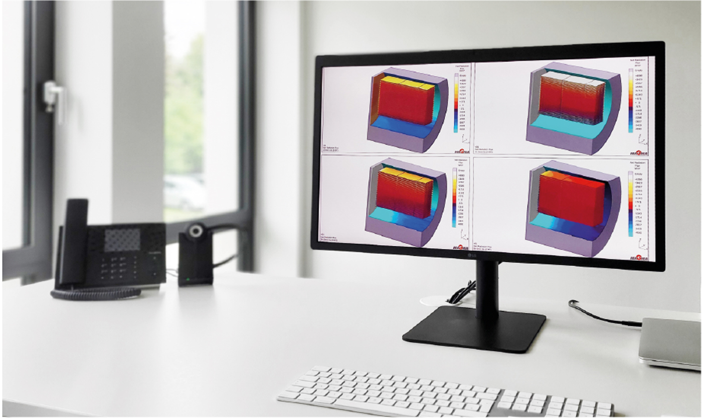
In the example shown, the target temperature of 1,400°C should be reached everywhere in the furnace after 3½ hours and then held at uniform, steady-state temperatures in the furnace for another 1½ hours. However, the calculation shows a different picture: the temperature distribution between the sintered parts is clearly inhomogeneous: when the furnace temperature had just reached 1,400°C, the temperature differences were up to 100°C and, at the end of the holding time after a total of 5 hours, the temperature differences were still up to 34°C (Fig. 3). In this example, the radiant heat source is at 1,400°C and, due to vacuum sintering and the fact that the sintered parts are thermally decoupled from the tungsten plates by insulating alumina mats, no further types of heat transfer need to be considered.

In order to understand exactly what leads to the obviously inhomogeneous and transient temperature distribution in the furnace, it is useful to investigate the heat flows in the furnace. In the case of vacuum sintering, the determining variable is the heat radiation between all areas of the furnace, the rack and the sintered parts, as well as the heat conduction within all components represented in the model.
The calculations show that, at the beginning of heating, the sintered parts facing the susceptor are exposed to a high heat flux of up to 3,500 W/m2, while the sintered parts placed in the centre of the furnace receive almost no heat. The heat is emitted from the susceptor and absorbed by furnace walls, the inside of the furnace door and, of course, the rack and the sintered parts. The question of emission or absorption arises from temperature differences of the surfaces, between which radiant energy is exchanged.
In the holding phase, considerable heat is still exchanged, which is due to the permanently-existing temperature gradients in the furnace. Conversely, this means that if a heat flow is displayed in the calculation, temperature differences prevail and the temperatures in the furnace are uneven (Fig. 4). It is both interesting and easy to see how much heat the unheated furnace door absorbs during the entire sintering process.

For the simulations quoted above, the thermal conductivity of the green compact was set at 50% of the reference value for the thermal conductivity of the 100% dense material. The increasing values of the thermal conductivity due to the density increasing during sintering were considered by a linear approach from 40 to 100% during the time from onset to complete sintering.
Temperature- and time-dependent thermal conductivities of sintered parts: the link between calculations on powder-scale and furnace-scale
The work described below was carried out for a stainless-steel alloy (316L) and was aimed at developing a method for determining the thermal conductivity of sintered parts during sintering [3]. The motivation arises from the necessary assumption that the material of the sintered parts is homogeneous throughout the complete sintering process for furnace-scale simulations. It was mentioned above that the enmeshment of the simulation model allows a local resolution down to just below 1 mm, which is about two orders of magnitude too coarse in relation to the powder-scale.
Looking at the microscopic structure of a green part, one finds gas atomised steel particles of almost spherical shape and a certain size distribution and spaces between the powder particles filled with inert or reaction gas or vacuum (Fig. 5).
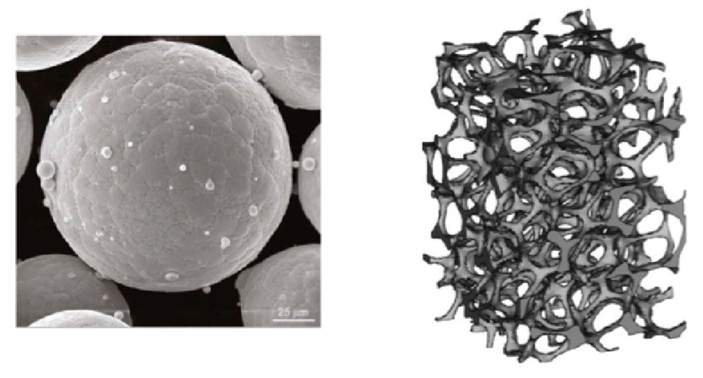
The heat transport through a green body is thus built up by two dominant mechanisms: To begin, there is the thermal conductivity within the steel spheres. Before the part starts to sinter, the heat transport between the steel spheres is clearly dominated by radiation. However, this strongly depends on the prevailing surface temperatures. Considering the extremely small contact area between the steel spheres, the heat transfer between the steel spheres can be neglected at this point.
The following approach to modelling the thermal conductivity of a sintered part before and during powder-scale sintering is based on this situation.
The components that make up a loaded sintering furnace, on the one hand, and a loaded vacuum heat treatment furnace, on the other, are basically the same: steel parts and vacuum. Verified numerical heat transfer models have recently been developed for the vacuum heat treatment of steel parts [2], which should be a useful basis for calculating the thermal conductivity of sintering probes before and during sintering.

The following approach is proposed for such a ‘virtual determination’: a standard virtual bar specimen was designed in CAD, consisting of steel spheres of one fraction and vacuum in the interstices. Varying the diameters of the spheres allows the variation of a steel/vacuum ratio between 57% (where the steel spheres are just touching) and 100% (no more vacuum volume). The varying steel/vacuum ratio corresponds to a sample during sintering, where the density ranges from about 57% for the green part to 100% for the dense part.
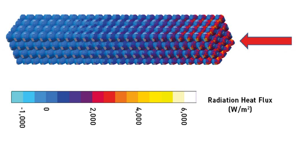
In the example shown in Fig. 6, one end of a 57% dense virtual sintered sample was exposed to a 1,000°C radiant heat source and simulated using the verified heat transfer model for radiation in vacuum of Fainberg and Schäfer [2]. The heat is transferred in the longitudinal direction of the sample. It can be observed how the radiation first heats the side of the first particles facing the heat source. Then the heat is conducted through the particles, which in turn transfer heat by radiation to their colder neighbours in the shadow of the heat source.
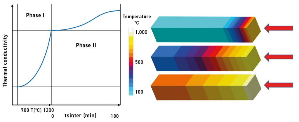
The result is a transient temperature distribution in the virtual specimen (Fig. 7). This combined heat transport from thermal radiation in the interstices of the specimen and thermal conduction within the powder particles leads to a characteristic transient temperature distribution in the specimen.
Due to the complexity of the physical relationships considered in this microscale model, the calculation takes some time, but provides detailed answers to questions about the heat transfer in green parts.

For the simulation of macroscale transient 3D heat transfer in complete furnaces or at least in furnace segments, with hundreds to tens of thousands of sintered parts, this approach cannot be used without enormous computing times, even on computer cluster. For this reason, an approach is needed that helps to move from the microscale analysis of heat transfer in detailed sintered samples (see above) to a macroscale analysis of sintered parts in a furnace.
It was proposed that the detailed geometric model of the discrete virtual sinter specimen, as shown in Fig. 6 and Fig. 7, should be replaced by a model with a continuum structure, but with temperature- and time-dependent thermal conductivities, as obtained from the above-mentioned heat transfer simulations of the virtual sinter specimen.
Two characteristic phases were defined: firstly, the heating phase, in which the thermal conductivity of the sample is determined by the temperature-dependent effects of heat conduction through the steel particles and radiation between them and secondly, the isothermal sintering phase, in which the thermal conductivity is determined by the same effects. The increasing amount of thermal conduction within the powder particles as they form an increasingly dense structure during sintering is considered (Fig. 8, left).
The methodology used here is based on a virtual DOE, where the individual virtual specimens have different thermal conductivities. The respective individual simulations in the DOE use the same boundary conditions as the heat transfer simulation of the microscale simulations described above. In the automated evaluation of the results, the variant out of the DOE with the smallest deviation from the given transient temperature development of the detailed sintering specimen is searched for, as shown in Fig. 6 (and Fig. 8 right).

From the assessment of furnace temperatures to optimisation
As previously shown, heating and even holding phases in sintering furnaces are transient; at the same time, the temperature distribution in a sintering furnace is non-uniform at any time. When taking this into consideration, questions should be raised about process improvements to get closer to steady-state and uniform temperatures during sintering.
However, the development, testing and realisation of alternative heating concepts that could enable more uniform furnace temperatures is, of course, risky, time-consuming and cost-intensive. One of the most interesting effects of virtual test methods, however, is that many technical approaches, even exotic ones, can be evaluated and documented with little effort and in a short time.
In batch sintering furnaces, the heating elements are, at least, located on the sides of the furnace chamber, sometimes additionally on the bottom and top. The reason for this is that, in this case, a rack carrying all the sintered parts can be loaded into the furnace in one step. What is somewhat neglected here is the above-mentioned problem of transient, non-uniform temperatures to which the sintered parts are exposed.
An admittedly exotic approach would be to install additional vertical heating plates parallel to the charging direction of the furnace. A virtual DOE was carried out for a virtual test and to document the possible effects of different heating element designs in a sintering furnace [3]. The variants have a different number of heating plates: the standard version: two plates at the sides of the furnace chamber, a version with one additional plate and a version with three additional heating plates (Fig. 9).
With one additional heating plate (Fig. 9 centre) the temperature distributions clearly become more even – and this proportionally more true when more heating plates are added (Fig. 9 right.) If there are only heating plates at the sides of the furnace, the temperature difference between the parts near the heating plate and those in the centre of the furnace is about 35°C. This temperature difference is reduced to about 20°C with an additional heating plate in the centre of the furnace and to less than 6°C with a total of five heating plates.

The behaviour of green parts during thermal debinding
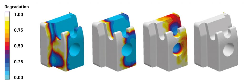
During thermal debinding of MIM and sinter-based AM green parts, defects may occur. These can be explained, for example, by uneven binder decomposition and the resulting uneven transient strains and stresses. The non-uniform binder degradation may in turn be due to non-uniform temperatures in the sintered part.
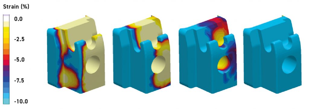
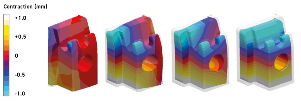
The decomposition of a binder can be described by an Arrhenius function, whereby the activation energy can be determined via thermogravimetry. In the example described below, a single sintered part from the calculation above was examined in more detail (see Fig. 9). A sintered part was selected from the centre of the rack, immediately next to the radiant heat source. As a result, a green part in this position is exposed to a particular risk due to uneven, one-sided exposure to heat. The size of the sintered part is about 30 x 30 x 30 mm. The transient inhomogeneous temperature of the sintered part was used as a boundary condition for the calculation of the binder degradation (Fig. 10). This binder degradation naturally leads to a characteristic elongation of the green part (Fig. 11), and this, in turn, leads to an equally characteristic contraction of the green part (Fig. 12). To calculate this three-dimensional shrinkage, gravity-induced creep of the binder at temperatures below the decay was considered. A popular Cam-Clay model [e.g. 5] was utilised for the calculations.
Concluding remarks
In this article, some examples are shown where the thermal processes in sintering furnaces and sintered parts are very conclusive, which brings to question why these phenomena, which are known in principle, should be analysed and optimised with the aid of complex calculation models at all? The authors’ aim here was not to document concrete solutions for concrete problems, but to demonstrate the methodology of virtual assessment and virtual process optimisation and to point out their potential.
Authors
Dr.-Ing. Götz Hartmann and Dr. rer. nat. Wilfried Schäfer, MAGMA GmbH and Dr. Jesper Thorborg,
Technical University of Denmark
MAGMA GmbH
Kackertstrasse 16-18,
52072 Aachen,
Germany
[email protected]
www.magmasoft.de
References
[1] G. Hartmann et al., “Fast and efficient optimization of the load temperature distribution in high temperature sinter furnaces”, Euro PM2017, Conference Proceedings, Milano, 2017.
[2] Fainberg J. and Schäfer W. 2015: “A fast and efficient adaptive parallel ray tracing based model for thermally coupled surface radiation in casting and heat treatment processes”, Proceedings of the 14th International Conference on ‘’Modeling of Casting, Welding and Advanced Solidification Processes (MCWASP XIV)’’, Hyogo, Japan 21 – 26 June, 2015.
[3] G. Hartmann et al., “Virtual sinter process optimization – a holistic multiscale approach”, Euro PM2018, Conference Proceedings, Bilbao, 2018.
[4] J. Thorborg, J. Klinkhammer and H-J. Gaspers: “Integrated modeling of deformations and stresses in the die casting and heat treatment process chain”, Giesserei-Special 01/2018, Giesserei-Verlag Düsseldorf 2018, p54ff.
[5] Roscoe K.H. and Burland J.B., 1968, On the generalised stress-strain behaviour of ‘wet’ clay, Eng. Plasticity, Cambridge Univ. Press, 535-609.