


MIM feedstock trends in Asia: Competition, innovation, and market shifts
The Metal Injection Moulding industry in Asia is experiencing significant shifts in feedstock sourcing and material usage. While BASF’s Catamold remains a key player, competition is growing, reshaping supply chains and production strategies. In this article, Dr Q (Y H Chiou) explores the evolving landscape, examining market and application trends, regional variations, and the increasing role of domestic Chinese feedstock manufacturers. As demand for complex, high-performance MIM parts rises, understanding these changes is essential for industry stakeholders. [First published in PIM International Vol. 19 No. 1, Spring 2025 | 15 minute read | View on Issuu | Download PDF]
The recent World PM2024 Congress, held in October in the vibrant city of Yokohama, Japan, brought together MIM industry representatives from around the world. While attending, I unexpectedly met with Nick Williams and Jon Craxford from PIM International – a happy surprise that sparked insightful discussions on the future of Metal Injection Moulding technology in Asia.
My presentation at World PM2024 set the tone for some of these discussions, including how PIM feedstock sourcing is changing across Asian markets. Does BASF SE, with its Catamold product, continue to dominate the feedstock market, or have there been shifts in the competitive landscape? Here, I will address these pressing questions and offer insight for readers from the global MIM industry.
More than fifty years after the earliest form of PIM was developed as a manufacturing process for ceramic applications, BASF’s 1984 invention of polyoxymethylene (POM)-based MIM feedstock marked a milestone. This innovation provided a stable and efficient alternative to the wax- and water-based feedstocks that had been the norm from the early days of MIM. This is not to say that wax-based and water-based feedstocks are disappearing; they continue to play an important role in the global MIM market, particularly in the specific applications where their properties are best suited.
Table 1 provides a comparative analysis of the three major feedstock systems and hybrid wax/POM, highlighting their respective advantages, challenges, and uses across different sectors. While BASF’s POM-based feedstock remains key in industries such as automotive, aerospace, and consumer electronics, the East Asian market, in particular, is seeing increasing diversity in feedstock sourcing, driven by growing demand for more complex, high-performance parts.

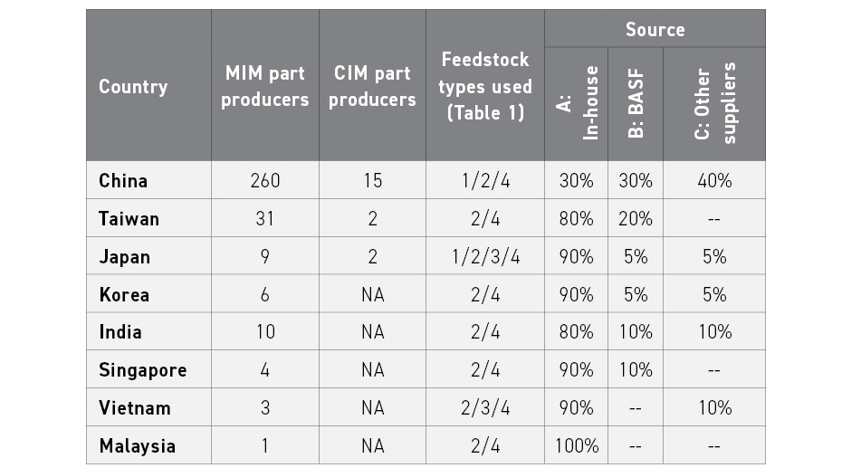
Based on data from my ongoing industry analysis, Table 2 shows feedstock usage trends in major PIM-producing countries across Asia. Materials for CIM include alumina, zirconia, ferrite, glass, and other ceramics, with production concentrated in China and Japan.
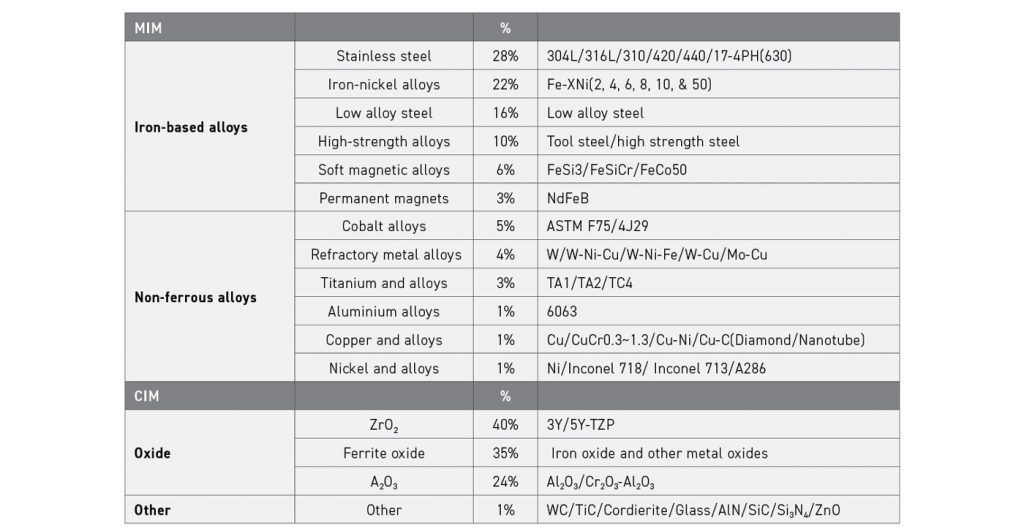
MIM is usually centred around iron-based low-alloy steels, iron-nickel alloys, and stainless steels, collectively known as the ‘three brothers’ of the major MIM materials. Their use significantly surpasses other materials. While cobalt and nickel alloys hold a share, their total usage remains far lower than that of high-specific gravity tungsten alloys. The use of other non-ferrous materials such as copper, titanium, and aluminium has been gradually increasing in China.

Estimating the market
PIM International readers worldwide may be curious about the continued success of BASF feedstock in Asia: How many tonnes of its feedstock is sold in Asia today? What is its share of the total regional feedstock supply, and what is its total share of MIM feedstock in the Chinese market? The following analysis considers these questions.
Asia’s total MIM parts sales value for 2023 is estimated to be just over $2.7 billion, rising to $3 billion in 2024, and is dominated by China and Taiwan, followed by Japan and India. Table 3 provides a detailed estimate of the average powder and feedstock prices in China.

In the estimate for 2023, the material cost of a MIM part accounted for approximately 10% of the minimum sale price. Therefore, the Chinese MIM industry spent around $200 million ($2 billion × 0.1) on MIM feedstock that year. According to Table 2, feedstock sources were distributed as follows:
- 30% In-house production (A)
- 30% BASF (B)
- 40% Outsourced (C)
The average unit prices of powder, Chinese feedstock, and BASF feedstock (as listed in Table 3) were used to estimate consumption:
In-house produced feedstock
- Total cost: $60 million (30% of $200 million)
- Average powder price: $8.5/kg
- Estimated powder consumption: ~7,000 tonnes ($60 million, $8.5/ kg)
BASF feedstock
- Total cost: $60 million (30% of $200 million)
- Average feedstock price: $12.5/kg
- Estimated feedstock consumption: ~4,800 tonnes ($60 million, $12.5/kg)
Purchased Chinese feedstock
- Total cost: $80 million (40% of $200 million)
- Average feedstock price: $10/kg
- Estimated feedstock consumption: ~8,000 tonnes ($80 million, $10/kg)
Based on these calculations, BASF is estimated to have sold between 5,000 and 6,000 tonnes of MIM feedstock in the Asian market. Estimating sales for other MIM and CIM feedstocks remains challenging, however, due to customer confidentiality requirements and product functionality differences.

MIM applications in Greater China
Table 4, which details applications for MIM products, is based on insights gathered from interviews across the Greater China region (Mainland China, Taiwan, and Hong Kong). Distinguishing these highly interconnected markets remains challenging, something made more difficult by the fact that many Metal Injection Moulding companies from Taiwan and Hong Kong have established manufacturing branches in Mainland China.

Material usage remains dominated by the iron-based ‘three brothers’, a position further strengthened because Apple no longer uses cobalt-chromium-molybdenum alloy (ASTM F75) in MIM products. Tungsten and titanium alloys continue to find applications, while aluminium and copper alloys are slowly beginning to see more prominent use. Nickel-based alloys are rarely used.
Table 5 shows the classification and market share of materials using CIM/MIM across Greater China. In CIM, aluminium oxide structural materials remain the most used. This is followed by iron oxides, which are widely used as an inductive material. Aluminium oxide plays a key role in the semiconductor industry’s high-temperature fixtures, while other ceramic materials are used mainly in industrial accessories for semiconductors.
Market dynamics
Growing demand for functional materials
The demand for magnetic materials is increasing daily. In addition to soft magnetic materials (e.g. iron-based metals and ferrites), high-flux density neodymium iron boron (NdFeB) permanent magnets also leverage PIM technology to produce complex geometric shapes. Anti-magnetic metals and composite materials have also adopted PIM technology.
The use of thermally conductive materials has expanded significantly, primarily driven by the heat-dissipation challenges of fibre optic communication chips. There is also a demand for GPU chips, which include graphics processing chip units. Materials with high electrical conductivity, thermal conductivity, and/or insulation properties are in demand. These include the addition of diamond or nanocarbon materials to copper to improve thermal performance. These types of complex parts require MIM technology to achieve both intricate geometries and enhanced thermal performance.
Emerging applications and market shifts
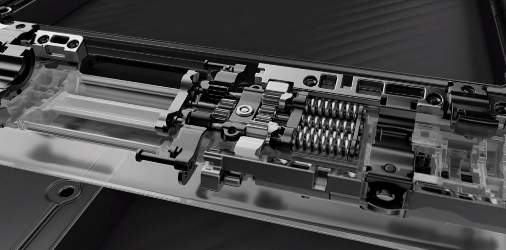
The production of high-strength, lightweight MIM hinges has increased substantially, and these are now being shipped in large quantities (Fig. 2). This is driven by their use in smartphones with foldable screens and tablets, as well as in the automotive industry, where traditional dashboards are being replaced by large tablet-style display screens, with foldable screens a potential development. The development of these technologies relies heavily on high-strength MIM materials.
Chinese MIM factories no longer rely on the demand for consumer electronics applications; instead, they are exploring opportunities to replace conventional casting, precision investment casting, and die casting applications. Even press and sinter PM processes, in particular for stainless steel parts, now face competition from MIM technology. Numerous commonplace metal hardware components are quietly being replaced with MIM products, and components in larger sizes (100-1,500 g) are gradually appearing in the market.

Advancing in green PIM technology
I have actively promoted ways to further reduce the environmental impact of MIM technology in China, with one of the most significant successes being the production of stainless steel 304/316 powders (excluding low-carbon variants with C wt.% > 0.03) from scrap. One example involved the sourcing of a relatively large quantity of high-purity scrap from stainless steel processing waste in the Jieyang area of Guangdong Province. This material was atomised into powder for MIM feedstock, reducing costs by over 10% compared to market prices. Although not low-carbon, parts made from these powders passed stringent salt spray tests. The key is to sinter with rapid cooling to prevent the formation of chromium carbides (Cr26C6 and Cr6C3), which, by depleting grain boundaries of chromium, can cause local corrosion problems.
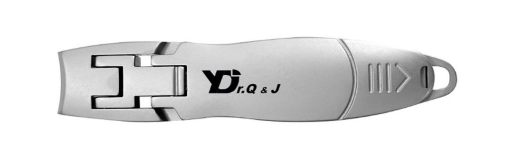
Additionally, stainless steel 420 scrap from kitchen knife production in Yangjiang were successfully recycled and atomised into powder, then used to manufacture high-quality nail clippers via MIM (Fig. 3). Following the MIM process and heat treatment to achieve >HRC 45, these products demonstrate the potential for increasing MIM-based recycling efforts in the future.
PIM of glass
The Shanghai research base is actively developing a process for recycling broken glass for PIM applications. PIM technology is already capable of producing complex geometric products in a translucent ivory-like colour, with transparent recycled glass PIM products expected to be completed next year.
Tungsten alloys
The injection moulding of complex tungsten alloys with extremely fine powders (D99 < 5 μm) is also advancing. Improved powder dispersion technology has enabled successful feedstock production. Meanwhile, the feedstock shrinkage ratio has also exceeded the BASF norm (1.165) and moved towards 1.126, indicating a powder loading capacity of 70 vol.%. This pushes the boundaries of moulds and injection moulding processes while maintaining shrinkage control at approximately <12%, which can help more accurately control sintering distortion.
Although the capabilities of PIM factories in China vary significantly, the vast market demand provides multiple opportunities for PIM products across different levels. Of course, progress in this field requires continuing breakthroughs from powder manufacturers alongside ongoing innovation and refinement from equipment manufacturers.
The future evolution of POM-based feedstock in China
The impact of Apple’s adoption of BASF’s Catamold feedstock into the region cannot be overstated. This standardised feedstock enabled PIM green parts to have high strength, and the rapid acid-catalysed debinding process substantially reduced the challenges of conventional binder technologies. This ensured that brown (i.e. debound) parts more easily retained their shape and size, significantly improving both production efficiency and the precision of finished PIM products.
Following the expiry of BASF’s patent, however, over fifty POM-based feedstock companies started to supply variants worldwide, the majority of which were sold in the Greater China region. However, there have also been cases of Chinese-made POM-based feedstock being exported to India, South Korea, Japan, Poland, and several Southeast Asian countries. As a result, PIM ‘whole-plant’ technology has also begun to be exported, including powders, feedstocks, and equipment (such as injection moulding machines, debinding furnaces, sintering furnaces, and heat treatment furnaces) [1-2].
The importance of powder characteristics on POM feedstock
Powder consists of a vast number of fine particles whose collective behaviour depends on their fundamental properties. Before proceeding, it is essential to analyse these particles’ fundamental characteristics to understand how they interact and influence POM-based feedstock development.
Fortunately, advanced inspection equipment is now available to assess the key characteristics of powder, often referred to as the ‘4S’ characteristics of size, shape, surface condition, and safety.
Size of powder
POM is a high-molecular-weight polymer that is prone to decomposition during injection or mixing processes. Over the past decade, many MIM operators have voiced their concerns after experiencing issues with its decomposition. When POM breaks down, it turns into gaseous formaldehyde, which not only has an unpleasant odour but may cause explosions if equipment operation errors occur. This is precisely why I emphasise the importance of the final S in the 4S characteristics: safety must always be a top priority.
In September 2023, a fatal explosion took place in Shanghai during an aluminium alloy build at an Additive Manufacturing equipment company. The reason was straightforward: light metals in a highly reactive fine powder form cannot be exposed to air, for example, when operators are opening and replacing the filter element of a Laser Beam Powder Bed Fusion (PBF-LB) machine [3]. Additionally, once ignited, such fires must never be extinguished with water. This was the cause of a devastating incident that resulted in the loss of four precious young lives, reinforcing the urgent need for comprehensive safety education in powder-forming industries.
One of the most overlooked aspects of powder management is particle size distribution (PSD) analysis. Most studies focus on D10, D50, and D90 values, assuming that controlling these ensures a well-shaped Gaussian distribution and, consequently, high-quality PIM products. However, little attention is given to the extremes – D1-9 and D91-100 – despite academic research emphasising the significance of D97.
In high-volume factory production, this limited focus can lead to critical oversights. During final quality inspections, rust spots are frequently observed on stainless steel 304L and 316L parts, causing them to fail stringent salt-spray tests and corrode severely within 24 h. This issue is largely attributed to the presence of both coarse and ultra-fine powder particles (Fig. 4) [4].
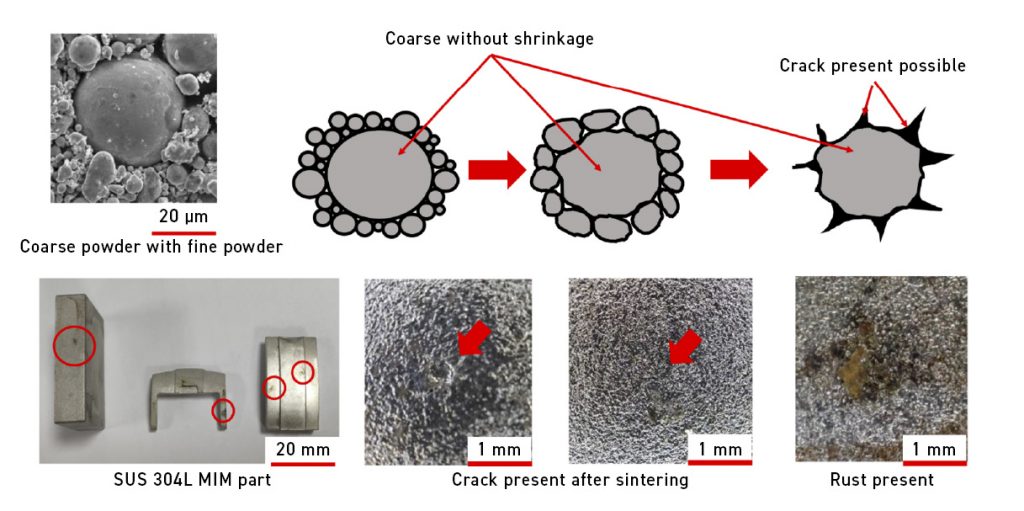
While it is well understood that finer powders in PIM technology enhance density, reduce surface roughness, and improve dimensional accuracy (Fig. 5), academic research methods often fail to fully align with real-world industrial production.

Powders smaller than 10 μm present significant challenges due to their extremely high specific surface area. As these fine powders move through closed systems – such as the barrel and screw of an injection moulding machine – they generate increasing forming pressure and frictional heat. This, in turn, accelerates the decomposition of POM-based feedstock.
In industrial settings, operators frequently rely on high temperatures, pressures, and injection speeds to maximise efficiency. However, this practice has been a primary concern regarding POM-based feedstock over the past decade.
Shape of powder
Fig. 6 illustrates the ideal powder shape, as proposed by Prof Randall German in 2007. In fact, the shape of the rice grains we eat in our daily lives is very similar to the optimum powder used in PIM. Rice, a staple food for many Asians, was something I used to buy by measuring it with a cup as a child. I recall that when loading rice, intentionally tapping the cup on the tabletop allowed more rice to fit inside.
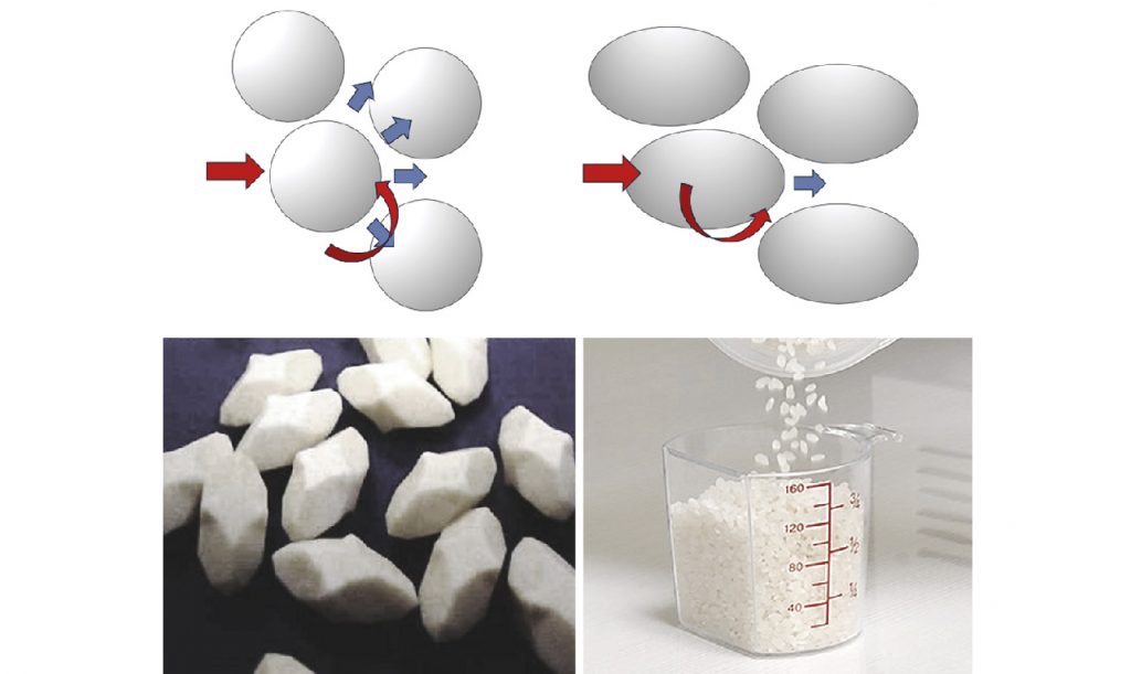
Similarly, powders with a rugby ball-like shape tend to pack more efficiently than those with a spherical shape. The pulling force of the process causes the long axis of each powder to advance in the same direction. Much like tapping rice into a cup, this alignment increases the packing density of the powder.
Surface conditions of powder
Powder with a rough surface does not necessarily hinder production with POM base feedstocks; instead, it can improve the powder-binder adhesion. Many research papers discuss this, so we will not go into significant detail about the powder’s surface state.
Safe use of powder
In addition to the high risk of combustion and explosion associated with highly reactive metal powders, powders with small particle sizes also pose a risk of dust inhalation. Powder technology practitioners need more on-site operators, guidance, and training. Human negligence and disregard may cause many otherwise avoidable accidents, reinforcing the importance of rigorous safety protocols and ongoing education in the industry.
The impact of powder on the performance of POM-binders
Various polymers can make up POM-based feedstock. As the feedstock compounding process involves the use of heat and pressure with a high-shear blade, high-molecular-weight polymers experience higher temperatures, at which there is a significant risk of thermal decomposition.
It is essential to understand that the molecular chains of polymers have a limited lifespan, and the number of rotations of the mixing screw can exceed the lifespan of the polymer molecular chain. As a result, POM-based feedstock becomes brittle and prone to decomposition. We can monitor and control this process by combining screw rotations with temperature and pressure control. This allows us to track degradation and estimate how much useful life remains before it becomes ineffective.
Observing the characteristics of the feedstock material
When using a feedstock, one of the standard methods for monitoring its performance is to use the ISO 1133-1 standard to measure the melt flow index (MFI) at a loading of 21.6 kg at 190°C [5]. Instead, the testing should be conducted across a temperature range of 170-240°C, with measurements taken every 5°C. The data are shown in the process trend chart in Fig. 7.

We can immediately determine the optimal flowability range for a given batch of POM-based feedstock. Low-temperature and low-pressure injection moulding is the best solution for POM-based feedstock injection moulding operations. Additionally, we suggest that every batch of recycled sprues undergoes MFI value measurement. You can then narrow down the temperature range between 175°C and 200°C, with readings still taken at every 5°C scale.
It is important to check whether the recycled material’s flow index has fallen below the supplier’s recommended value. For example, BASF Catamold 316L feedstock should have an MFI value greater than 800 g/10 mins. If the value drops below this threshold, it could indicate issues with material degradation, which may affect the overall quality and performance of the final products.
Why use an MFI tester?
MFI testing equipment is widely used to inspect traditional plastic injection moulding feedstocks. Figs. 7 and 8 show an MFI tester according to international standards: a heated capillary tube measures the weight of POM-based feedstock after it flows through for a fixed period of time, converting this measurement into a value expressed in g/10 minutes.
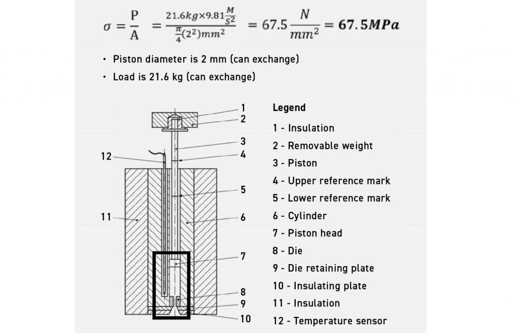
When applying the mathematical formulas, we can calculate the stress applied during a test. In fig. 8, the thrust applied to the POM-based feedstock is approximately 67.5 MPa, equivalent to the injection pressure of the injection base. This means the MFI tester can effectively simulate injection conditions, providing valuable insight into the feedstock’s flow characteristics before it undergoes the injection moulding process.
What makes this even more insightful is the ability to observe the surface of the extruded material strip. By examining this, we can assess the quality of the raw material after injection and determine whether recycled feedstock, which has been used multiple times, is still viable for use in the production process. This helps ensure that feedstock maintains its integrity over numerous cycles, ensuring consistent quality in the final product.
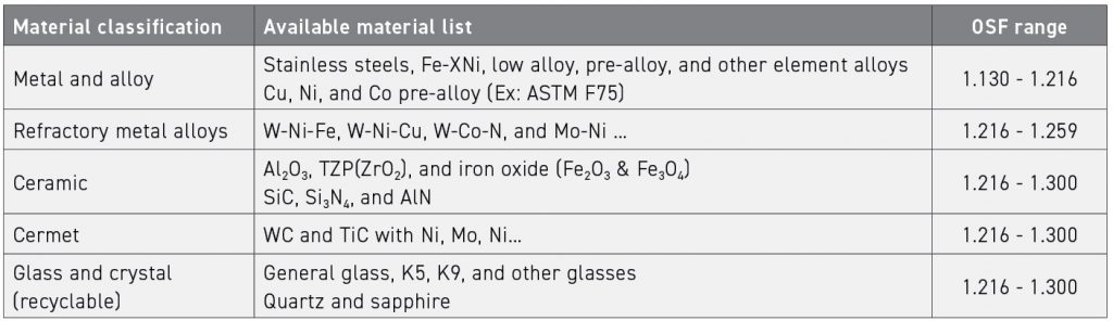
Currently available POM-based feedstocks
Table 6 shows successful POM-based feedstocks based on my 2024 survey. The ‘4S’ of powder affects the material’s oversize shrinkage factor (OSF) ratio value; these characteristics also play a crucial role in determining the OSF ratio of the powder. It is commonly known that the higher the OSF value, the less powder and the more binder is used. Fine powders, due to their higher specific surface area, require more binder to achieve optimal flowability. Therefore, a larger OSF ratio typically results in an increased shrinkage from the green body to the sintered part.
However, the design of OSF requires continuous experimentation, including chemical properties (such as activity and potential difference) and physical properties (such as specific heat capacity and thermal conductivity) of powders. These factors significantly influence the selection of the optimal ratio.
For reference, most POM-based feedstocks use OSF=1.165, which was the standard adopted by early BASF products. Representing the volume of metal powder: volume of binder = 63.2 vol.%:36.8 vol.% [6-7].
The OSF evaluation method is based on the size tolerance range of MIM parts, typically with a linear error of ±0.5%. Therefore, it is marked as OSF = 1.165 ± 0.5%, with a range of 1.165 × 0.005 = 0.005825. According to this calculation, the OSF range is from 1.1592 to 1.1708. Due to variations in the geometric shapes and surface conditions of powders, each feedstock company uses its own set of calculation methods. The quantity of powder is large and difficult to calculate, making it challenging to establish a unified approach.
Conclusion
Since BASF introduced POM-based feedstock, the standard OSF value of 1.165 has remained largely unchanged. However, the future of POM-based feedstock is clearly moving toward a lower shrinkage ratio (i.e. a lower OSF value). This shift will result in higher powder-loading capacity and a reduced amount of binder, allowing for more precise dimensions in MIM parts post-sintering.
While feedstocks with a low OSF value offer advantages, they also present challenges. These materials are often more difficult to mix and inject successfully, and the corresponding moulds require precise adjustments to accommodate the new feedstock’s characteristics.
A deeper understanding of powder characteristics and OSF optimisation will be key to advancing POM-based feedstock, ensuring greater precision, efficiency, and reliability in future manufacturing. To achieve this, I suggest beginning with a focus on powder particle size and shape. Manufacturers and researchers must develop their own feedstock and conduct multiple experiments to drive continuous improvement.
Author
Dr Q (Y H Chiou)
You neeD Technical Office
[email protected]
References
[1] Y.H. Chiou, “Riding the storm: A review of progress in China and Taiwan’s MIM industry during 2020”, M. Powder Injection Molding International, Vol.15 No.1 (2021), 99-104
[2] Y.H. Chiou, “What drives the success of an industry: chance or strategy? Lessons from the growth of MIM in China”, M. Powder Injection Molding International, Vol.15 No.4 (2021), 97-102
[3] THC Childs, Hauser C., Badrossamay M. “Selective laser sintering (melting) of stainless and tool steel powders: experiments and modelling”, Proc. Inst Mech. Eng. B. J. Eng Manuf. J. 219 (4) (2005), 339–357
[4] R.M. German, ”Powders, Binders and Feedstocks for Powder Injection Molding”, M. Powder Injection Molding International, Vol.1 No.1 (2007), 34~39
[5] ISO 1133-1, “Plastics -Determination of the melt mass-flow rate (MFR) and melt volume-flow rate (MVR) of thermoplastics”
[6] X. Kong, T. Barriere*, J.C. Gelin, “Determination of critical and optimal powder loadings for 316L fine stainless-steel feedstocks for micro-powder injection molding”, J. Journal of Materials Processing Technology 212 (2012), 2173-2182
[7] Y.H. Chiou, “The math in the magic: Calculating the sintering shrinkage of MIM parts”, M. Powder Injection Molding International, Vol.16 No.2, (2022), 97-101


