


Industry insight from the 2024 International Conference on Injection Molding Metals, Ceramics and Carbides
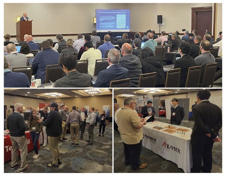
MIM2024, the International Conference on Injection Molding of Metals, Ceramics, and Carbides, was held in Raleigh, North Carolina, from February 26 to 28, 2024. Attended by more than a hundred delegates from ten countries, this latest event in the well-established series was deemed to be an innovative success. This year was – to the relief of both attendees and the Metal Powder Industries Federation (MPIF) – an in-person only event. Dr Animesh Bose, CEO, Optimus Alloys, reviews some of the highlights from the technical programme. [First published in PIM International Vol. 18 No. 2, Summer 2024 | 40 minute read | View on Issuu | Download PDF]
The purpose of the MPIF’s annual MIM conference is to survey the advances in the injection moulding of metals, ceramics and carbides, foster innovation, and act as a conduit for cross-fertilisation and technology transfer across different areas of Metal Injection Moulding (MIM), Ceramic Injection Moulding (CIM) and sinter-based Additive Manufacturing (AM). The event also serves to keep the community updated about other technologies that could impact markets in both positive and negative ways.
This year’s conference included twenty-five technical presentations that focused on some of the recent advances in MIM, CIM and sinter-based AM processes, materials, testing, tooling, and sintering. The technical programme was well augmented by ten minute presentations by various companies during the ‘Technological Process and Product Innovations’ sessions that highlighted each company’s respective technology. Nearly thirty companies showcased their products and services during a tabletop exhibit that was well-attended.
Several Metal Injection Molding Association (MIMA) functions took place alongside the conference, including meetings of the MIMA Standards Committee, the MIMA Board of Directors and MIMA member meetings. As is tradition, a PIM Tutorial was organised by the MPIF prior to the event, conducted by Matt Bulger, a former MIMA president.
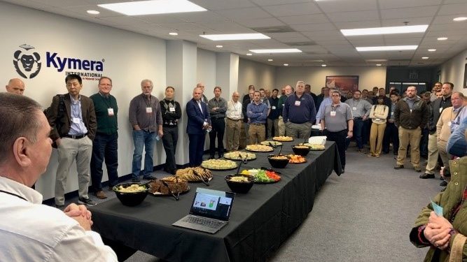
One additional attraction at this year’s event was a reception and tour of Kymera International’s copper (alloys and oxide), tin and antimony powder and paste plant in Research Triangle Park (RTP), North Carolina. Approximately sixty people attended, taking the opportunity to network with Kymera staff.
MPIF continues its mission of educating the next generation of PM professionals by engaging students and exposing them to the world of PM technologies, including MIM and sinter-based AM. Student participation was encouraged through the provision of five grants that allowed students to attend the conference and immerse themselves in the technology. Two of the five were from Europe.
These grant recipients were exposed to a plethora of insightful presentations, as well as being provided with the opportunity to connect with other professionals, gain exposure to the MIM industry, and grow their network. Additionally, each of the five students was given the opportunity to present the research they were engaged in at their universities. The five student grant recipients this year were Margarete Hufnagl, Montanuniversitaet Leoben, France, Ian Wietecha-Reiman, Penn State University, United States, Juan Jiminez Alumbreros, UCLM – Universidad de Castilla-La Mancha, Spain, Fatou Ndiaye, University of Louisville, United States, and Kaustubh Deshmukh, Virginia Tech, United States.
This review will only be able to cover a small number of the presentations delivered at the conference. So many of the presentations added value to the industry, meaning that the task of selecting what to feature in this report was a difficult one. My apologies to those presenters whose work could not be covered due to space restrictions.

Environmental, Social and Governance (ESG)
The opening keynote lecture – ‘ESG/Sustainability: A smart decision that goes beyond regulatory compliance’ – was delivered by Barton White, CEO, Kymera International. White’s first slide pointed out that the comprehensive approach to ESG adopted by Kymera shows an unwavering commitment to the triple bottom line: People, Planet, and Profits. He pointed out that Kymera’s approach to ESG includes measurable objectives, an emphasis on safety, inclusive reward structures, and community engagement to further the company’s well-rounded dedication to responsible business practices.
White then delved into more details on the three parts of ESG. In the environmental portion, the question was raised: when did the environment become a global concern? To the surprise of many, White stated that the answer is as far back as 500 BC, when some ancient yet forward-thinking authors discussed concern for environmental degradation resulting from human activity. However, in modern times, according to White, Theodore Roosevelt was the first US president to really take action, establishing approximately 230 million acres of public lands between 1901 and 1909, including 150 national forests. Some sixty years later, it was JFK who became the first to talk about ‘climate control’ in 1961 – a topic broached by every US president since. ESG as a whole, however, only came into prominence in 2006, when companies were encouraged to ‘put their money where their mouth is.’
It is well known that the PM industry is significantly impacted by the transition from the Internal Combustion Engine (ICE) to Electric Vehicles (EVs). However, as often is the case, stated White, commitments are often made by government and companies without fully realising what they are signing up for. This, he stated, was the case with the EVs, when, in April 2023, the US Government mandate was that two-thirds of new vehicles sold in the US must be fully electric by 2032. In 2021, GM committed to only sell EVs by 2035 – but in 2023, GM sold 76,000 EVs compared to its total of 2.6 million, or 3% of its (volume) sales. The 2023 sales of EVs were 1.1 million (7.6% of total volume), while 2024 sales are forecasted to reach 9.6%.
White pointed out that EV inventory remained in stock for an average of 113 days compared to only sixty-nine days for ICE and hybrid vehicles. He also pointed out that EVs, despite zero tailpipe emissions, are not necessarily as environmentally friendly as one may first think, and have their own issues with the social and governance portions of ESG. This, he stated, was particularly the case with regards to mining for raw materials.
Another concern with EVs, according to White, is the lack of necessary infrastructure. Currently, Level 1 charging (plugging into a domestic wall socket) takes 40-50 hours to charge. Level 2 charging points (the type of charger that EV owners will typically install at their residential address), takes 5-10 hours to charge – or overnight. Level 3 charging stations (known as superchargers, or DC Fast Chargers) take 30 minutes to 1 hour to fully charge.
White stated that to meet 2030 mandates, >2 million Level 2 charging points and >200,000 Level 3 charging stations will be needed, costing an expected $25 billion. For reference, in 2023 fewer than 25,000 Level 3 charging stations were operational in the US. White also raised the case of power failures, especially in the event of a natural disaster when evacuation is required.
In comparison, it was stated that significant improvements to ICEs have been made, and continue to be made. Toyota and Mazda have vastly improved the thermal efficiencies of their vehicles’ engines, meaning the fuels are more efficient (burn off slower) and thus efficiency improved. Other areas of improvement in ICE-based vehicles include better aerodynamics, cylinder deactivation when a car is stopped, and turbocharging, which have also improved fuel efficiencies over the years.
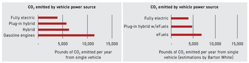
White stated that some of the alternate types of vehicle power sources that are currently being developed include hydrogen-based fuel and eFuels. Currently, Shell and Exxon are working to develop novel eFuels. Shell is developing a blend of second-generation ethanol derived from sugar cane waste and other biofuels to create a fuel that is 100% comprised of feedstocks categorised as ‘renewable’ under the applicable regulatory frameworks. This eFuel is expected to produce 60-80% less CO2 compared to traditional fuels. If one considers the CO2 emissions, it can be observed that gasoline engines are bad (emitting nearly more than double than that of other types of power sources) while all electric and plug-in hybrids with eFuel are the two lowest CO2 emitters.
The social impact of ESG, according to White, is often overshadowed by the environmental aspects. He stated that the social aspect of ESG is meant to reduce social inequalities (defined ‘condition[s] where people have unequal access to valued resources, services, and positions in society’) in the workplace and beyond. He outlined five types of inequalities: racial, wealth, gender, geographical, and educational. White commented that the ‘S’ should humanise ESG inside the workforce through competitive compensation, positive company culture, trust, fairness, communication, professional development, diversity and inclusion.
White went on to state that the ‘G’ (Governance) in ESG also does not receive as much attention as it should. In governance it is important to pay attention to the following: board composition; business ethics; anti-corruption; incentive structure; and supply chain management. He went on to add that corporate governance is foundational to the realisation of ESG, and makes his case by raising the question that if there is a question around the ethical behaviour of an organisation, how can stakeholders trust that the reported environmental data is accurate? And, if employees and customers do not trust an organisation’s ability to operate fairly, employee turnover will increase, customers will look for alternate suppliers and investors will be wary of management’s ability to drive success. White cited the examples of Volkswagen’s emission test scandal and Facebook’s misuse of data.
ESG accreditation can now be done through EcoVadis, a globally recognised business sustainability rating provider. Scores account for efforts relating to the following ESG themes: environmental, ethics, labour/human rights, and sustainable procurement. White stated that Kymera’s 2027 goal is to be among the top 1% of all EcoVadis-rated companies. He stressed Kymera’s employee-centric initiatives – as well as its governance – for transparency and accountability that leads to overall stakeholder confidence.
White concluded his presentation stating, “Sceptics will say that ESG is just a money pit and adds no value to an organisation, but I think it is the complete opposite. Not only because it is the smart thing to do, but also because it’s the right thing to do.”

Case study: MIM vs PM
Jason Osborne and Jeff Howie, from Alpha Precision Group’s MIM Division, part of Nichols Portland Inc, co-authored an interesting presentation entitled ‘Comparison of MIM and conventional PM material properties, cost considerations and other business case factors for an aftermarket medical hardware component.’
Osborne, who presented the paper, stressed that for the purpose of such a study, a part must be carefully chosen to ensure that it can be fabricated by both the conventional PM ‘press & sinter’ process, as well as by the MIM process, without the part offering any major advantage or disadvantage to either.
The investigation was prompted by current economic conditions (high interest rates and inflation) that have negatively impacted the business case for new capital equipment, leaving some businesses more likely to repair and refurbish equipment, or turn to the used or refurbished equipment market for their immediate needs.
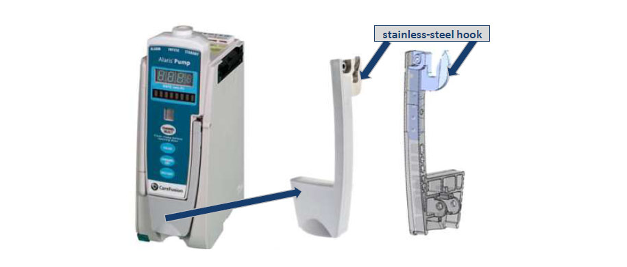
These conditions offer growth potential for the service parts industry supplied by OEMs and aftermarket suppliers. The part exemplifying this was a medical infusion pump module that sells for $2,600 for a new OEM unit, with the cost of a refurbished or aftermarket version costing between $550 and $850 (referenced prices were based on Google Shopping search results for ‘Alaris 8100 Infusion Pump’).
The OEM replacement parts offer performance and durability identical to the original factory parts because they are manufactured from the same PM tools, using the same production process, material and acceptance criteria. However, OEM replacement PM parts are more expensive as the manufacturing process, which is best suited for high-volume production, is not cost-effective for lower-volume replacement needs.
Aftermarket providers can offer different designs, manufacturing processes and materials, ranging from low-cost ‘knock-offs’ to premium solutions that provide improved durability and/or performance. A technically-savvy aftermarket supplier can develop a solution that is both cost-effective and better performing than the OEM service part.
This presentation detailed one case study of the aforementioned medical infusion pump module produced by two different technologies: (a) the OEM assembly where the component is produced using conventional PM technology and (b) the aftermarket assembly where the component is produced using MIM. The presentation compared the material properties, performance, and enterprise cost of the aftermarket and OEM production.
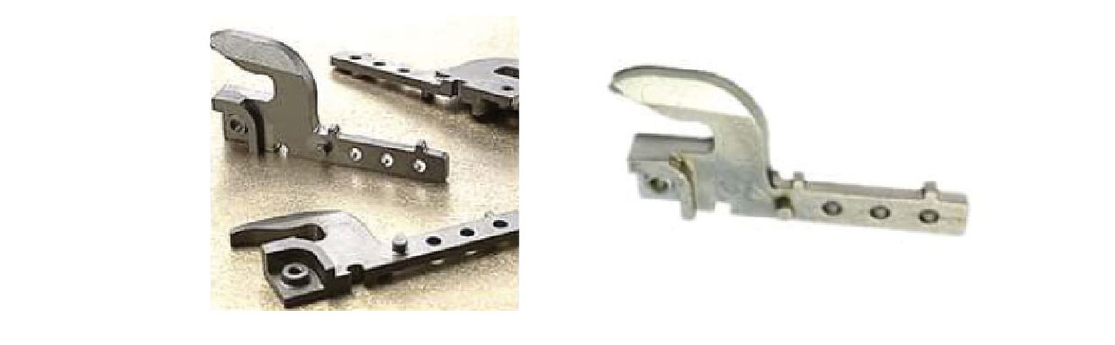
The findings showed that MIM technology offers a competitive, robust solution for the lower-volume aftermarket requirements. The OEM production model uses a door latch sub-assembly with a conventional PM stainless steel hook while the lower-volume aftermarket and refurbished models use a MIM stainless steel hook in the door latch sub-assembly. The replacement cost of door latch sub-assembly is ≈ $80+ for the OEM version, and ≈ $35-48 for an aftermarket version (referenced prices based on Google Shopping search results for ‘Alaris 8100 Infusion Pump replacement door latch’).

The presentation went on to provide more details on the application and the requirements of the part. Due to the high cost and function of an infusion pump unit, its reliability is crucial; it will not function if the door latch does not sit properly. Functionally, the stainless steel hook is the most highly loaded component in the door latch system, and it must withstand regular opening and closing events. The hook interacts with a roller mounted to a spring-loaded stainless steel MIM latch component. As the application is a medical device, the hook must also be corrosion-resistant and able to withstand any contact with various disinfectant cleaners (ammonia, bleach, carbolic acid, hydrogen peroxide, etc.).

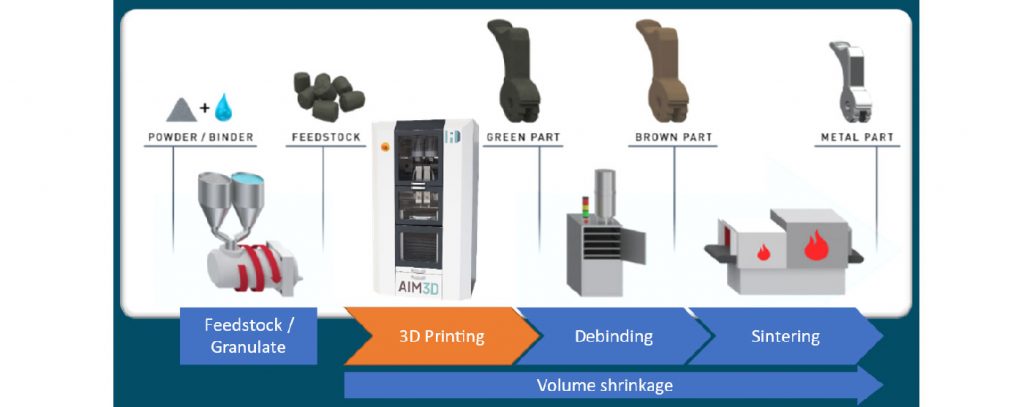
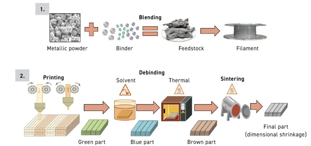
The processing steps for the PM and MIM components are quite different (as shown in Fig. 7), the most notable being in the green shaping technique (die pressing for PM parts and injection moulding for MIM parts); the debinding process; and the sintering process (a continuous furnace for PM parts versus a batch furnace for MIM parts). The resulting final properties do exhibit some differences as shown in Table 1.
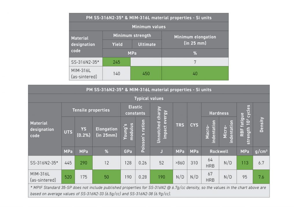
Conventional PM 316N-35 (nitrogen alloyed, sintered at 1,290°C in dissociated ammonia atmosphere) has high strength and good corrosion resistance compared to other conventional PM 300 series stainless steel alloys. It should be noted that the 6.7g/cm3 density equates to roughly 87% of theoretical density (13% porosity). MIM 316L has higher UTS, elongation and superior impact resistance compared to PM SS-316N. The 7.6 g/cm3 density for MIM parts equates to roughly 98% of theoretical density (2% porosity).
The higher sintering temperature (in a vacuum) and near full-density (98%) of the MIM-316L offers superior corrosion resistance compared to conventional PM 316N2, with a minimum of five times the corrosion resistance (<0.005 g/dm2/day vs. 0.024 g/dm2/day). A detailed cost estimate analysis was carried out when comparing the conventional PM versus the MIM process. The cost estimation had the following assumptions:
- Workplace fixed costs were based on new replacement cost of equipment, 10-year straight-line depreciation schedule, 10% interest rate, $7.70/ 0.09 m2 (1 ft2) cost for space (manufacturing space national average, January 2024), 245 production days/year, 3 shifts/day x 8 hours/shift, 80% workplace uptime
- Workplace variable costs were based on $0.08/kW-h electricity cost (national average, November 2023), $0.03/scf hydrogen cost
- Operator cost is $22/h labour cost (national average for non-union manufacturing labourer in 2022)
- Technician cost is $29.25/h (operator cost + 33% premium)
Osborne pointed out that the cost analysis does not include the following as they can vary significantly from one company to another: SG&A, workplace repairs and routine maintenance costs, tool refurbishment and replacement costs, indirect labour and overheads, scrap, and profit margin.
Based on the above considerations, Osborne and Howie concluded that lot sizes (quantity per set-up) play a big factor in which process is more competitive. Conventional PM is more cost-effective for production lots over 1,000 pieces, while MIM is a more cost-effective process for production lots under 1,000 pieces. This difference is primarily due to the set-up time required for conventional PM presses. Upfront tooling investment is different for each technology: conventional PM tooling for a ≈100t multi-level press (two upper punches, two lower punches, shelf-die, four core rods & adapter hardware) ≈ $25,000-30,000 while MIM dual cavity tooling for master unit die ≈ $17,000-20,000. Thus, the ≈ $5,000-13,000 difference in tooling cost has to be factored into the business case.

Based on the above cost considerations, the authors concluded that the enterprise cost for either technology is heavily dependent on the final customer volume requirements. If the customer only wants a one-time production run, MIM is more competitive up to ≈ 21,000 pcs. For recurring spot buys for lot quantities of 1,000 pcs or less, MIM has a clear cost advantage for both the up-front investment and the cost per piece. For lot quantities of 2,500 pcs, it would require more than thirteen orders before conventional PM comes out ahead (due to the higher up-front tool cost); for lot quantities of 5,000 pcs, it would require more than three orders before conventional PM comes out ahead; and for lot quantities of 10,000 pcs, it would require more than two orders before conventional PM comes out ahead. Any recurring orders over 21,000 pieces gives conventional PM the cost advantage.
In summary, the authors concluded that, from a performance standpoint, MIM-316L offers superior mechanical properties and corrosion resistance compared to PM 316N2-35. In theory, this should translate to a more robust aftermarket component with an improved lifespan compared to the OEM component. They also pointed out, however, that there is no data available showing the lifespan or failure mode of OEM versus aftermarket latches in the field. From a cost perspective, the MIM solution does offer a cost advantage at lower production volumes.
Typically, the volume for service requirements is a fraction of the production volumes, so MIM can be very cost effective for aftermarket applications, with the up-front investment for MIM tools also offering a lower cost of entry for new aftermarket applications. Unfortunately, the price of the aftermarket latch is roughly half the price of the OEM latch, which would tend to suggest that the aftermarket products are likely marketed as low-price alternatives rather than high-performance upgrades to the OEM latch. The price of a replacement latch (OEM or aftermarket) is low compared to the purchase of a new infusion pump unit, so it makes sense to replace the latch if it fails. However, it’s a nuisance whenever an expensive infusion pump unit becomes inoperable due to the failure of a low-cost part. The more robust MIM 316L hook reduces the likelihood of a repeat latch failure.
The authors concluded that different sinter-based technologies (conventional PM and MIM) both offer viable solutions for the stainless steel latch based on specific market needs. Conventional PM is a low-cost solution for the high-volume OEM production unit, while MIM is a more robust solution that offers cost advantages for lower-volume aftermarket service requirements. It is not often that presentations are made on a detailed cost comparison between two PM technologies, but this paper did an excellent job of a detailed cost comparison between conventional PM and MIM for the same part.
MIM machine parameters
Marko Maetzig from Arburg GmbH & Co KG presented a paper entitled ‘Machine setup and significant parameters to adjust the MIM moulding process.’ He had divided his presentation into two parts:
- Machine options for improved injection moulding for MIM that included drive technology, aXw
- Control ScrewPilot, PIM cylinder assemblies, and PIM nozzles
- Vacuum system and machine parameter setup and impact on the moulding process that included melt preparation, the moulding process, and monitoring.
In the area of drive technology, Arburg has a wide product range with a modular system – from fully hydraulic to fully electric, enabling optimum configuration to be achieved for each application. Various machine sizes with a practice-oriented range of clamping forces and injection units are also available, further driving customisation through modularity.
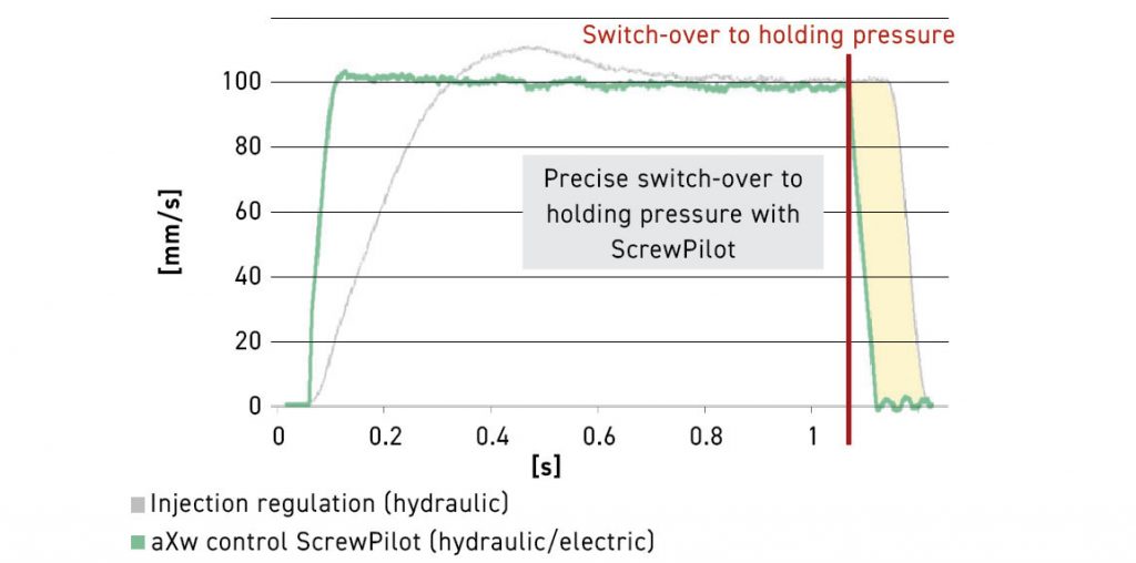
The aXw Control ScrewPilot provides a controlled injection process based on precise measurement of screw position, and the injection speed is actively adapted in the event of external fluctuations; it also allows for in-cycle control with the switchover point remaining constant.
Arburg also offers special automatic control technology for hydraulic injection units. The benefits of this system include even flow front characteristics, switch-over to holding pressure at the same filling level, and injection parameters that are unchanged, resulting in a stable injection process. This also provides high injection dynamics; dynamic and active braking (Fig. 8) is also possible.
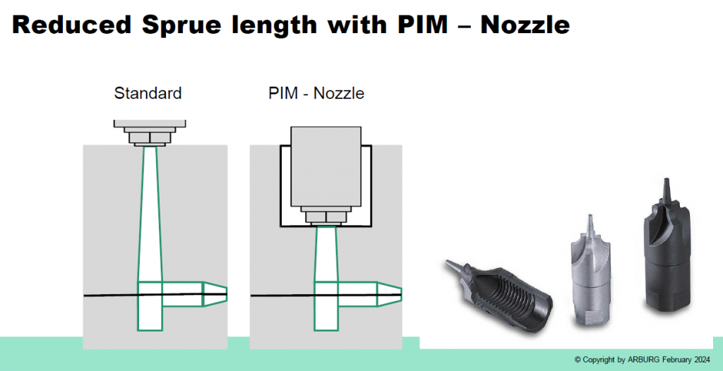
In the area of the cylinder assembly, Arburg achieves high wear protection and long service life through the use of a bimetal cylinder for MIM operations, whereas the cylinder for CIM has hardmetal liners. The screws for MIM processing are made from PM steel, while screws for CIM operations are made from hardmetal. The non-return valve is made with hardmetal inserts, with the option of having the non-return valve made from hardmetal drive technology. The nozzles incorporate a special design that results in a short sprue because of its extended length versus the traditional nozzle, resulting in optimal material utilisation (Fig. 9).
The vacuum system provides several advantages, including prevention of flow-line issues and binder migration, resulting in consistent part quality, the prevention of air inclusions, enabling complete mould filling, uniform filling behaviour, programming with dedicated symbols, and flexible programming that integrates all common vacuum concepts. A reliable evacuation that results in good process or quality control is achieved by the recording of signal patterns and their presentation in a monitoring visualisation, with the monitoring of extreme values and their precise evacuation sequence also taking place.
Ideal parameters
The parameter setup and its impact on the moulding process was covered in detail by Maetzig. He pointed out that the physical and thermo-physical properties of MIM feedstocks are substantially different from those of the binder, including the fact that the density of MIM feedstocks is typically 3.5 times the density of the binder; the heat conductivity of MIM feedstock is around 6 times the heat conductivity of the binder, and the heat capacity of MIM feedstock is generally around one-third of the heat capacity of the binder.
During melt preparation, the temperature adjustment of the plasticising unit is set to temperatures according to suppliers’ recommendations – preferably at lower end thereof to avoid overheating of the feedstock that can result in material degradation – while the feed yoke temperature is adjusted to the lowest melting point of binder components.
Dosage speed and the back pressure during dosing also play important roles in the melt preparation step. Low dosage speeds are generally preferred to avoid excessive shear of feedstock and it is recommended to use cooling time for the dosing process. Low back pressure during dosing is also preferred.

Nozzle retraction/sprue break should be used on moulds with cold sprue, and feedstock freeze-off in the nozzle at the mould contact area should be avoided. Pressure peaks during moulding and injection of cold slug should also be avoided. During the moulding process, attention should be paid to flow rate adjustments which, if too slow, can lead to premature freezing of feedstock and cold pushing; if it is too high, it can lead to powder-binder separation, air entrapments and burn spots.
Switch-over point adjustment is carried out when the fill cavity is 95-98% filled. If this is done too early, one can have filling via holding pressure with loss of position/speed control, while doing it too late can result in pressure peak and compressive stresses. Mould filling analysis is a helpful tool to analyse filling behaviour. To use this, it is recommended that the operator adjusts the flow rate and pressure used in production and keeps all holding pressure parameters to a minimum (flow rate, pressure, holding times), delaying the time for dosing and varying the injection flow rate to optimise filling.
Monitoring of injection parameters plays a critical role in the MIM process. The pressure at switchover point should be constant in order to achieve consistent part quality and a stable process. Pressure variation can happen if the switchover point is too late or too early, if different feedstock batches are used, or when changing the balance of virgin and re-granulated feedstocks.
Dosage time should also be kept constant to achieve constant cycle time and consistent part quality. Reasons for dosage time variations include cylinder and screw roughness, granulate size and size distribution, and the use of re-granulated feedstock.
In conclusion, Maetzig pointed out that the moulding process is an important step towards high-quality MIM parts, and the right moulding machine configuration can help achieve this. A good understanding of process parameters and setup is the key to achieving high-quality MIM parts.
MIM in firearms: an application study
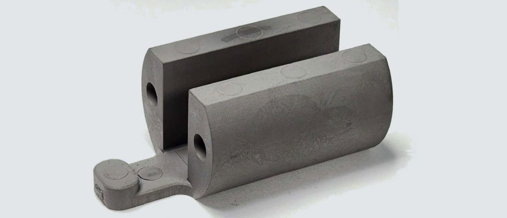
An excellent case study entitled ‘Utilizing Metal Injection Molding (MIM) in the manufacture of a large tungsten heavy alloy WHA firearms component – problems and solutions’ was covered in a presentation by Gaetano Mariella of PTI Tech Inc., New Jersey, USA.
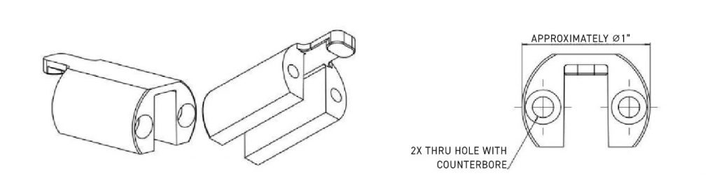
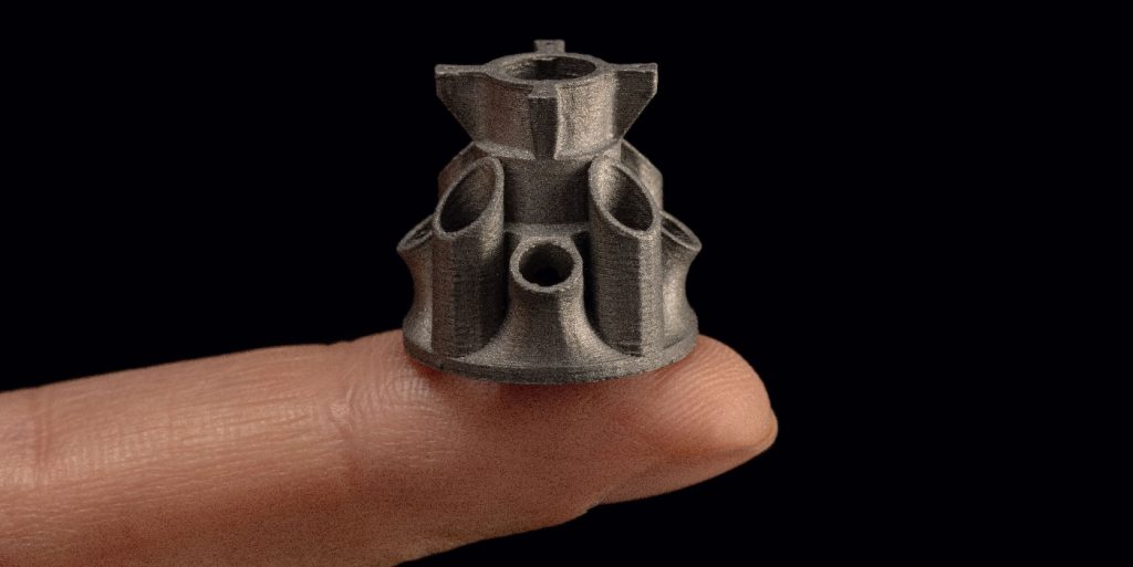
In the presentation, Mariella detailed the study based on a unique high-density tungsten-based alloy that was used to produce a firearm component. A major firearms manufacturer approached PTI Tech in search of a solution to a machined part. As part of the firearm’s bolt design, the customer required a component with a large amount of mass in a limited volume that would act as a dampening mechanism/vibration absorber.
Looking through the list of available high-density metals and alloys, most materials were removed from consideration as they were too expensive (gold, platinum), too difficult to process in the elemental form (W) or too toxic (uranium). The material that was found to be applicable was a class of tungsten alloy known as tungsten heavy alloy.
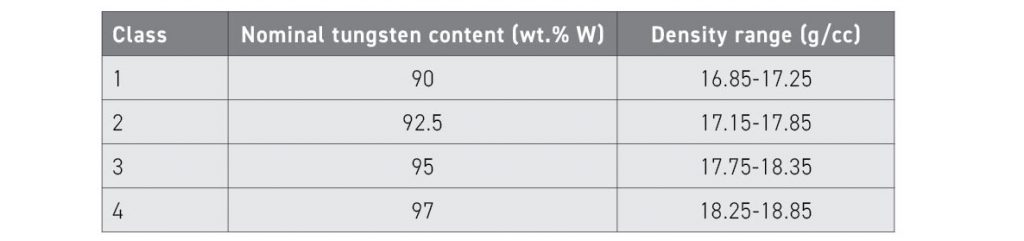
These alloys are a two-phase composite comprised of a pure W phase combined with a binder phase that contains some dissolved tungsten. Liquid Phase Sintering (LPS) of these alloys achieves >99.2% of theoretical density. The density of the alloys can be varied, and the final alloy density can be close to pure W. The alloy has good machinability, and common machining techniques can be employed. The alloy has strength similar to medium carbon steels, has a high elastic modulus (stiffness), low CTE, high thermal conductivity, and low toxicity. Depending on the alloy density, tungsten heavy alloys have been divided into several different classes as shown in Table 2.
The initial question was which composition would be best for the application. The issue with lower tungsten containing alloys is the higher volume of liquid that is formed during liquid phase sintering, which can result in slumping and distortion. The solution was to choose alloy compositions that would have lower liquid volumes (which then become the matrix phase), thus lowering the distortion. The alloy that was chosen for MIM production in order to mitigate sintering distortion and retain ductility had a composition of 95W-3.5Ni-1.5Fe wt. % and the alloy had a theoretical density of 18.16 g/cm3.
Another major design consideration was the thick cross-section of the lobes, which would create problems during the debinding process. PTI worked with the client to incorporate the largest through holes possible to facilitate the debinding of the thick cross-sections. This was a critical design modification that was needed for the part to be properly rebound.
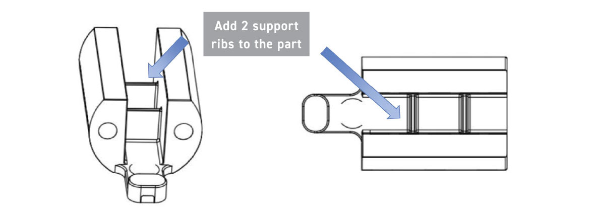
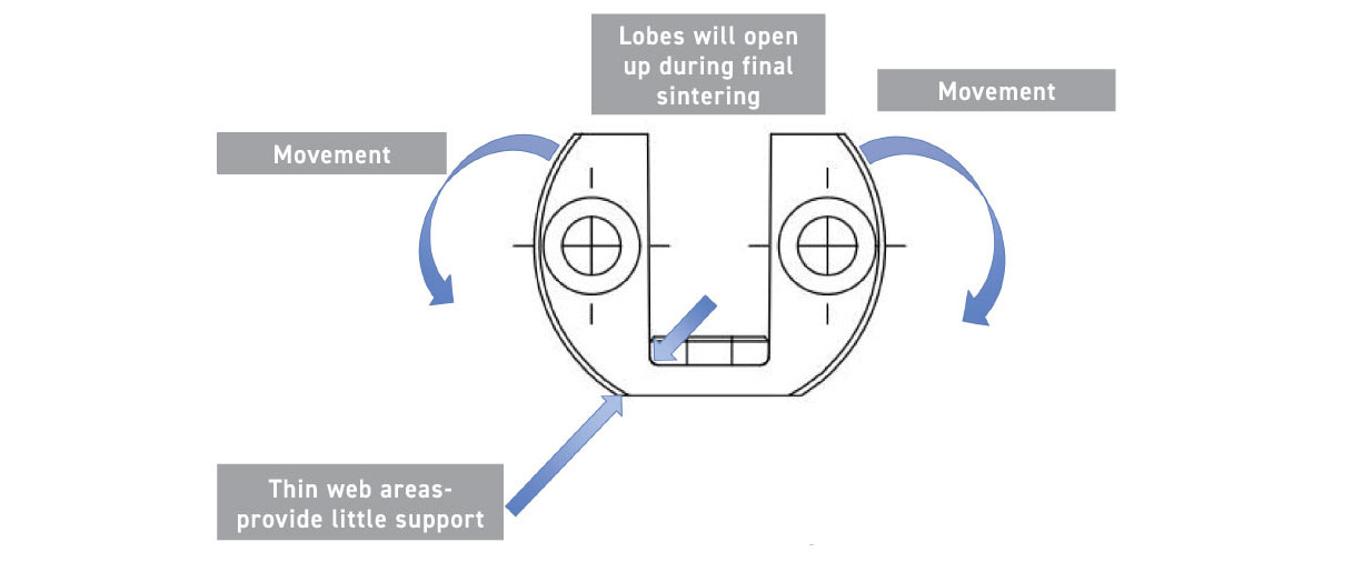
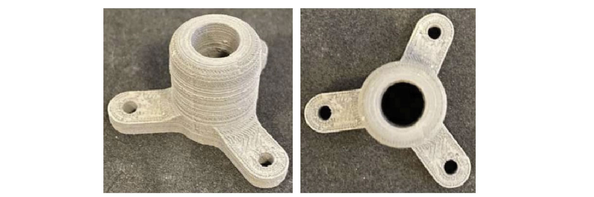
The next challenge was that the relatively heavy lobes, which had thin web areas at the bottom, tend to bend over during liquid phase sintering. To solve this, another design modification was made: two support ribs were added to the structure (Fig. 13) to mitigate the distortion of the part during liquid phase sintering. This would then add an additional step where the two support ribs would need to be removed by machining.
PTI explored several gate locations; configurations and sizes prior to final tab gate location shown in Fig. 14. The company had to iterate numerous moulding profiles to achieve a fully filled part with no large flow or knit lines. The parts were subjected to solvent debinding which was followed by thermal debinding. The final sintering was carried out in a pusher furnace, using a flowing H2 atmosphere, with a sintering temperature around 1,500°C peak temperature and a hold time of 2-3 hours.
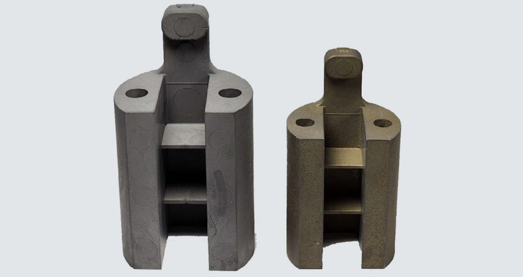
The final density of the part was around 18.0-18.05 g/cm3, which was more than 99% of theoretical density, and the part’s weight was around 250 g. There was significant shrinkage between the green and the sintered part as shown in Fig. 15. The two ribs and the tab gate are removed by machining to achieve the final part. This case study shows the successful fabrication of a large component made by MIM from a high-density tungsten heavy alloy.
Feedstock modification and debinding methodologies
An interesting presentation entitled ‘A review of the attributes and debinding methodologies of binders utilized in MIM process’, authored by Dwight Webster and Lane Donoho of Advanced Metalworking Practices (AMP), Indiana, USA, was presented by Webster.
It is not too often that presentations are on the subject of MIM binders and their modifications to achieve desired flow behaviour. This presentation reviewed two of the most common binder systems. It discussed methods of adjusting flow properties via various manipulations of the binder systems, and reviewed examples of applications.
Over the years, a multitude of mixtures of powders and binders have been formulated to make MIM feedstocks. Often, MIM processes are distinguished by the binder removal methods (debinding) of which the three common ones are based on water debinding (polyethylene glycol (PEG)-based), thermal-solvent debinding (wax-polymer based) and catalytic debinding (polyoxymethylene (POM)-based). This presentation focused on the latter two debinding technologies and their binder systems.
Generally, both binder systems have two main constituents: the primary binder (wax or POM) and the secondary binder (backbone binder). A multi-component binder system often has a few more minor additives, but the two primary constituents are the ones outlined as primary or secondary. The primary constituent typically accounts for more than 50% of the total binder composition (by weight) and is removed first, resulting in an open pore structure.
Once the primary binder is removed, the backbone material (secondary binder) provides the strength and integrity to support the subsequent handling of the parts. The backbone material is typically removed thermally as part of the sinter cycle. The open pore channels created in the structure after the primary binder removal creates the pathways for the easy removal of the secondary binder(s).
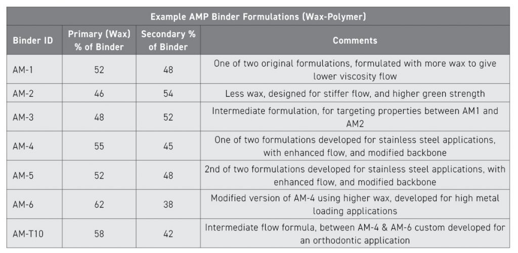
The feedstock produced at AMP is generally evaluated using a plastometer for flow behaviour, a gas pycnometer for the measurement of the feedstock density and a capillary rheometer that is also used to measure the flow (including characterising the viscosity versus shear rate behaviour). Examples of several wax-polymer-based binder systems are shown in Table 3. Keeping the solid loading constant at 59 vol.% using water atomised powder that has a d90 particle size of 16 µm, Fig. 16 shows the change in the viscosity when the percentage of the primary binder is varied.
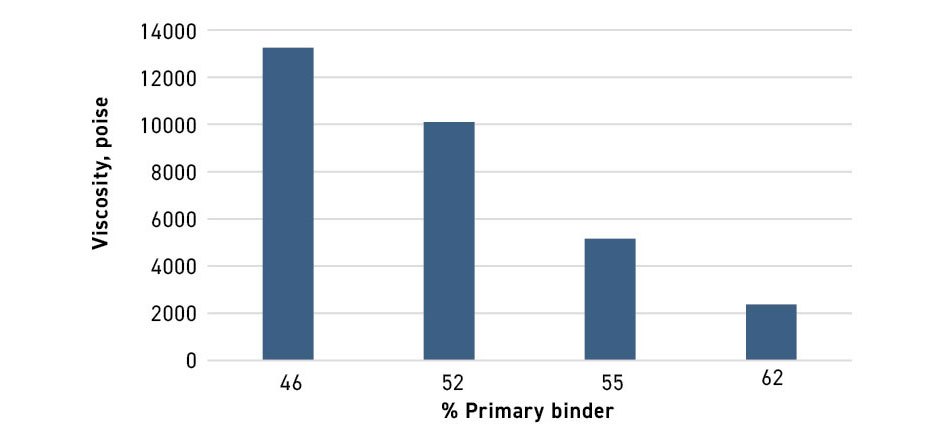
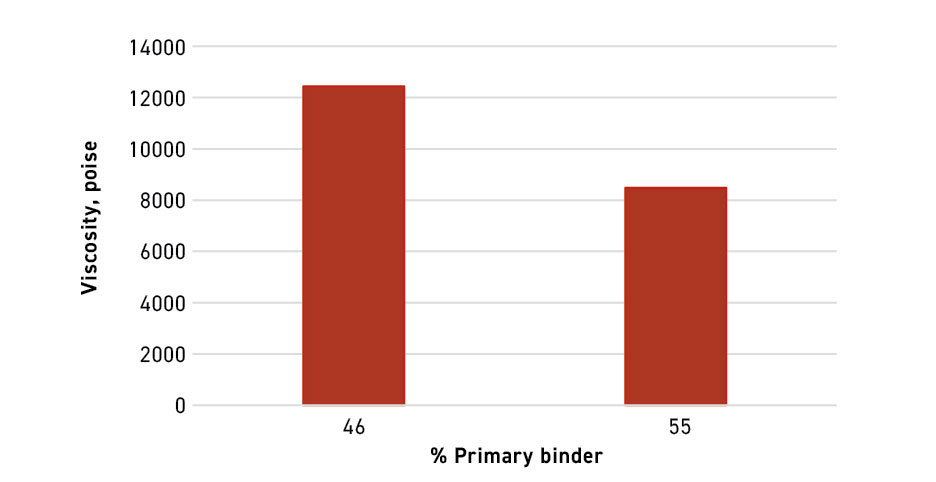
It can be observed that as the percentage of primary binder in the binder composition is increased, the viscosity of the feedstock is lowered. This behaviour does make sense, as the primary binder is generally the lower viscosity component of a wax-polymer-based binder system. A similar behaviour is also observed in the case of gas atomised powder where the solids loading is kept constant at 61 vol.% using a gas atomised powder with a d90 of 22 µm (Fig. 17). It is interesting to note that the gas atomised powder, even at the higher solids loading, shows a lower viscosity when the primary binder percentage is the same.
A case study with the wax-polymer binder system was described by Webster where AMP received an enquiry for a thin-walled part made from 17-4 PH stainless steel material and where the customer was open to using either the pre-alloyed powder or the master alloy blend. The customer was having difficulty filling parts with their current feedstock material. They also stated that the part was cost-sensitive and that target shrink equated to 60% solids loading.
Based on discussions with the customer, it was decided to use pre-alloyed water atomised powder having a d90 – 16 µm. Based upon AMP’s experience, it was suggested that the best flow option would be achieved with AM6, the company’s highest-flowing wax-polymer binder.
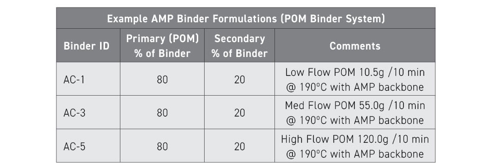
For the POM-based binder system, Webster presented three different systems (AC-1, AC-2, and AC-3) with the same percentage of primary and secondary binders but with three different POMs with varying flows. The first one (AC-1) was based on a low-flow POM that had a flow rate of 10.5 g/10 min at 190°C, while the next one (AC-2) had a medium-flow POM that had a flow rate of 55 g/10 min at 190°C, and the last (AC-3) had a high-flow POM that had a flow rate of 120 g/10 min at 190°C. The secondary material in all three binders was an AMP proprietary backbone component. The details of the POM binder system are shown in Table 4.
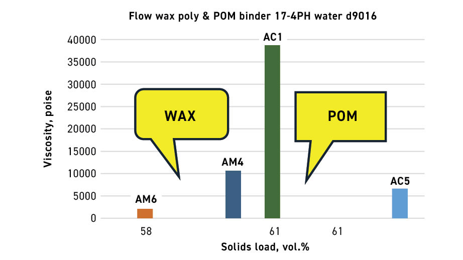
The presentation highlighted the differences in the viscosity between the wax-based and POM-based binder systems as shown in Fig. 18. For the same solids loading (61 vol.%), it can be observed that the POM-based binder (using the low-flow POM) has a higher viscosity when compared to the wax-based binder system. However, when using the highest flow rate POM – even when using a higher solids loading – the viscosity can be lower than the wax-based system. There are a few important pieces of data that will be filled in at a later stage (e.g. determining the viscosity of a feedstock that has a solid loading of 61 vol.% that uses the AC-5 based binder system and comparing it with the wax-based binder system as well as the AC-1 (POM-based) binder system).
A case study was also discussed by Webster that outlined the need of a customer who was trying to fill small components using a feedstock with a target loading of 62 vol.%. As the parts were small, AMP opted to first use the lowest viscosity binder system AC-5. However, the customer needed slightly lower shrinkage, so a feedstock was made with a slightly higher solid loading. The shrinkage was matched; however, the customer needed the parts to have a higher green strength. To achieve this, AMP made some modifications to its existing standard binder systems. After a couple of iterations, the company was able to achieve the customer’s desired target shrink and green strength requirements. The presentation also included a few other interesting case studies that have not been included in this write-up.
AM and MIM
In my report on last year’s conference, I pointed out the interesting trend of a steady increase in the number of sinter-based Additive Manufacturing (AM) presentations. This trend continued this year at MIM 2024, and, it would appear, the trend is here to stay. The inclusion of these papers is, of course, fully justified as more and more sinter-based AM processes with similarities to MIM are becoming mainstream and being adopted by both well-established MIM companies and startups.
This year, to serve as a lead into this trend, I presented a paper entitled ‘Several MIM-like sinter-based AM processes,’ discussing several sinter-based AM technologies that have close similarities with MIM. The presentation this year did not cover Binder Jetting (BJT), but chose to cover some of the less common AM platforms.
In all sinter-based AM platforms covered, the common thread was the mixing of inorganic powders and organic binders to form a feedstock similar to MIM feedstocks (or, in some cases, into flowable pastes). A significant part of the presentation was based on Fused Filament Fabrication (FFF), which falls within the Material Extrusion (MEX) category of AM technology. A part of the presentation focused on the Vat Photopolymerisation (VPP) process and a few technologies that are based on feedstocks in the form of paste.
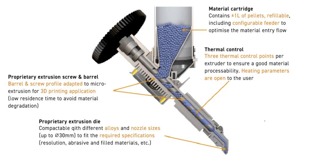
The presentation showed the subtle differences between some of the FFF platforms, stemming from the differences in the form of the feedstock material introduced into the heated nozzle for extrusion. The different forms of feedstock included material in the form of filaments wound into coils (a prevalent form of FFF practiced by Markforged, Fraunhofer IKTS, and several other research organisations and universities) and feedstock converted into solid rods that are used as the feed material, sometimes known as Bound Metal Deposition (Desktop Metal). A number of MEX processes now also use feedstock in the form of granules or pellets, as offered by Pollen 3D and AIM3D.
The surface finish of parts from such MEX-based platforms is not comparable with the smooth MIM surface finishes to which we are accustomed (prior to any secondary finishing steps).
In my presentation, I also introduced two hybrid processes (additive and subtractive) that have currently been commercialised. The first one is a process known as Moldjet practiced by Israel’s Tritone. This process first additively manufactures a mould cavity layer using an inkjet system, then follows it up with a pass of a paste material (from which the part is made) that is deposited and spread to fill the cavities created by the mould material.
The layer of the deposited mould cavity and the paste filling the mould cavity is inspected, and if a defective layer is detected, the layer is removed by micro-machining. The layers are then dried, and the process is repeated till the part is completed. The mould surrounding the part is removed by heating and the parts are subsequently sintered like MIM components and can achieve similar properties.
The second hybrid process is from Mantle 3D. This process starts with the formulation of a flowable metal or alloy paste that is extruded through a nozzle to form the desired shape. While still in the AM machine, the deposited layers are automatically shaped using high-speed cutting to improve the surface finish and detail. The parts are subsequently sintered to achieve the desired high density.
Mantle has focused almost exclusively on the business of forming moulds and mould inserts for injection moulding tooling. The tool has withstood more than 1.65 million cycles with no signs of wear. The additively manufactured H13 and P2X steel inserts have shown to be as accurate and durable as traditional S7 machined steel inserts. The time required to make the additively manufactured tools and inserts is significantly shorter than conventional machined inserts.
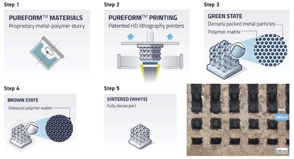
Another section of my presentation covered AM processes based on Vat Photopolymerisation (VPP) where technologies from three companies were touched on. The first company was Austria’s Lithoz, which focuses on what it calls lithography-based Additive Manufacturing. The company’s CeraFab Multi 2M30 uses the full capability of Additive Manufacturing to enable combined processing of different materials, such as ceramics and metals, in one single component, though the company primarily focuses on ceramics.
In its process, a ceramic slurry is automatically dispensed into a vat and the build platform is dipped into the slurry, which is exposed to light from below. This cures the entire surface of a layer at once, greatly speeding up the process compared to laser-based technologies. After undergoing a debinding and sintering process, the fully dense and high-performance AM parts are ready.
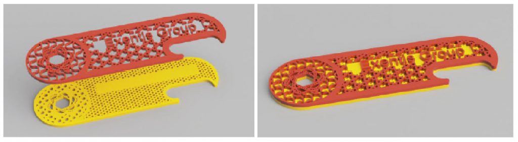
The second process covered was the Holo process, the processing steps of which are shown in Fig. 24. The figure also includes a shape that shows the ability of the process to create fine structures.
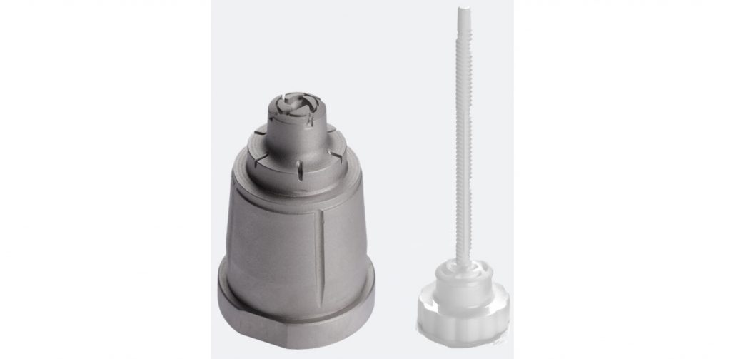
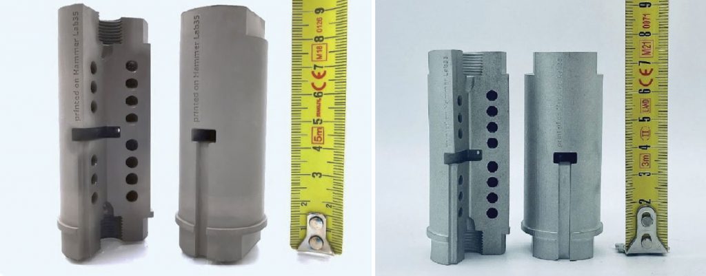
The last process presented in this series is a Vat Photopolymerization process mainly for metals and alloys that is practiced by Incus, an Austrian company which started as a spin-off from Lithoz. The company recently introduced a new larger metal Additive Manufacturing machine capable of producing metal parts with excellent surface quality (almost similar to MIM) and high reproducibility. Incus recently launched a larger AM machine, the Hammer Pro40, which has a build volume of 200 x 153.6 x 150 mm in the X, Y, and Z directions, respectively, as well as two scrolling projectors. The increased size of the machine makes it suitable for higher volume production with the same quality as the smaller predecessor Hammer Lab35 machine. The green part shown in Fig. 25 is around 90 mm tall and the sintered part is around 74 mm tall. A cross-cut section showing the internal structure of the full part is shown on the left of each image, while the full structure is shown on the right.
My last presentation topic was an AM process known as screen printing. Fraunhofer has conducted extensive investigations into this process, and so far, Exentis Group AG, Switzerland, and a number of global customers have commercialised the technology.
Eric Bert from Exentis North America presented on this technology in detail at the conference.
AM screen printing
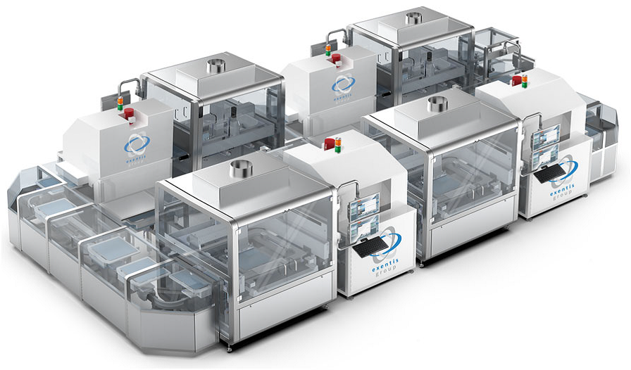
AM screen printing is based on making the desired powder into a paste that can then be extruded through the fine openings of a part-specific screen. Exentis has developed an Additive Manufacturing technology platform to create precision parts with ultra-fine structures using a conventional screen-printing approach combined with high-speed optical alignment and automated handling. This enables the mass production of complex parts using a wide range of materials, such as metals, ceramics, polymers, and pharmaceutical materials available in powder form.
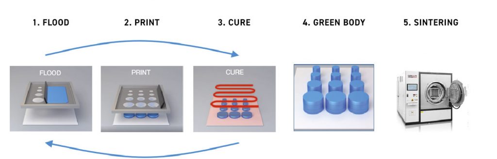
The specialised high-speed AM machines deposit layers of paste until the desired part height is achieved. The screen tools and optical layer alignment deliver ultra-fine part features in a repeatable manner while the high-speed, automated systems enable cost-effective mass production volumes, though it is important to recognise that changing the X-Y geometry in a part requires changing of the screen tool, which does add both cost and time. Also, this process limits overhangs, and internal channels are possible.
Layer thickness can be varied from 10-150 μm, enabling very fine feature resolution. The twelve-second stroke cycle times deliver full production-scale throughput. The process is geared for high-volume production of thousands to millions of parts.
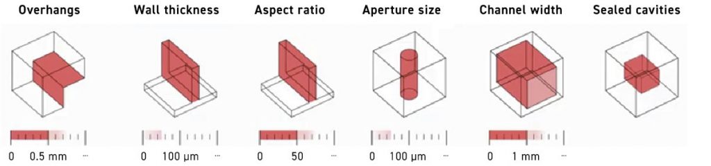
Exentis has extensive experience in screen manufacturing – a precision process with high accuracy and stringent cleanliness requirements (as the company also works in pharmaceuticals). The mesh size is flexibly selectable (20-500 μm and coarser), and the screening technology is mature (established for decades). The cost of screens is independent of the complexity of the screening structures, with screen tool costs ranging from $1-2K and having 50,000-80,000 stroke life.
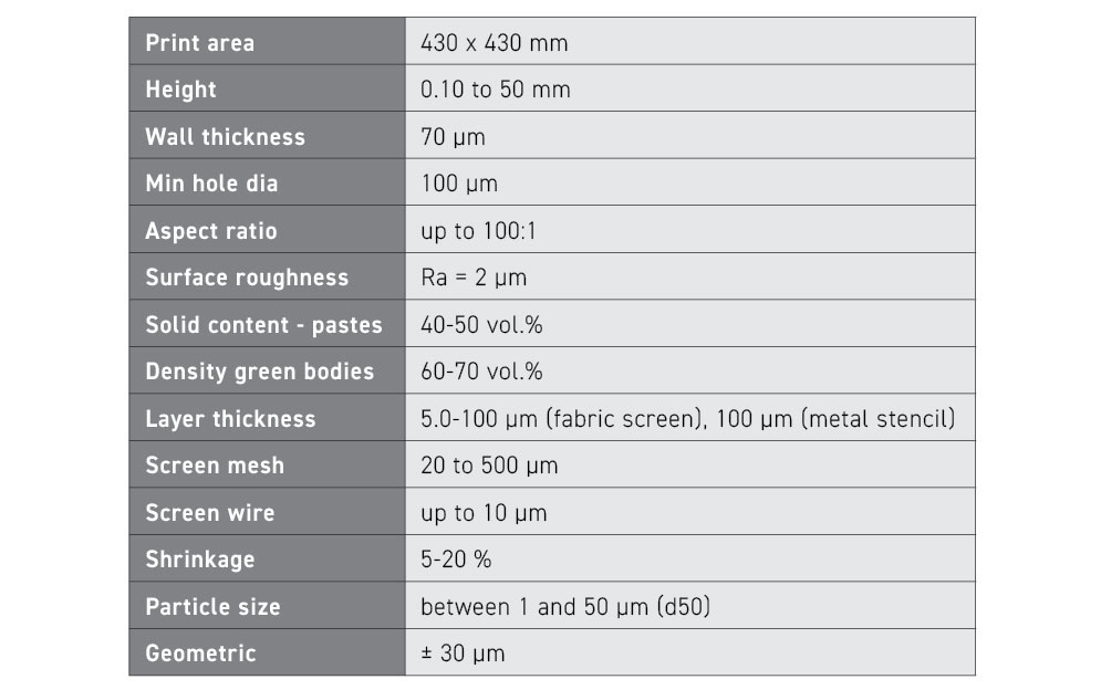
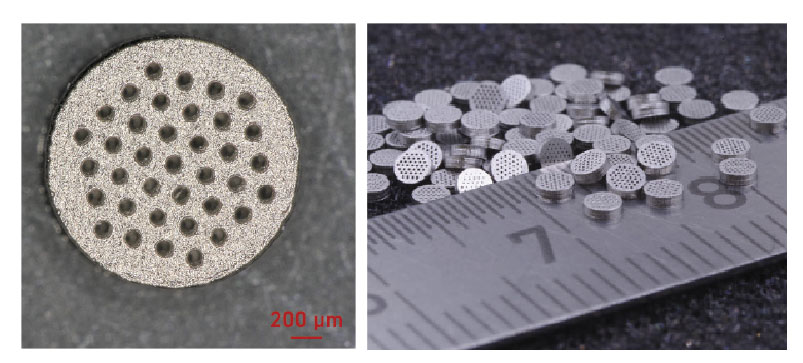
According to Eric Burt, since Exentis Additive Screen-Printing uses screens as hard tooling, “Very small, high-aspect-ratio holes, fine features, and precisely-toleranced parts that were previously outside the capability window of conventional and Additive Manufacturing processes are now achievable and available at costs that meet production requirements.”
Exentis has been selling systems in Europe since 2017 and is now in the process of building up a North American presence via the newly formed Exentis North America subsidiary in Boston, Massachusetts. Applications based on the Exentis Technology Platform are diverse and include precision heat sinks, complex filtration components, high-density electrical interconnection components, and bi-polar plates for hydrogen fuel cells.
FFF/MEX and mesostructured stainless steel
An interesting study entitled ‘Processing of mesostructured stainless steels using FFF technology’ was presented by Juan Jiménez-Alumbreros as part of the results of his master thesis at DYPAM Research Group at Universidad Castilla La Mancha, Spain, which was performed within the topic-related research line led by Dr Javier Hidalgo and Dr Gemma Herranz as the group leader.
The presentation introduced the concept of ‘multi-functional components by advanced processing technologies’, where two or more dissimilar materials can be combined into one component (copper/17-4 PH stainless steel; 316L/17-4 PH; AISI M2/ 316L). It emphasised the technological advancements in this field, enabling disruptive applications. Furthermore, the presentation outlined the current state of advanced complex phase (CP) steel, where different phases serve distinct purposes (Fig. 31).
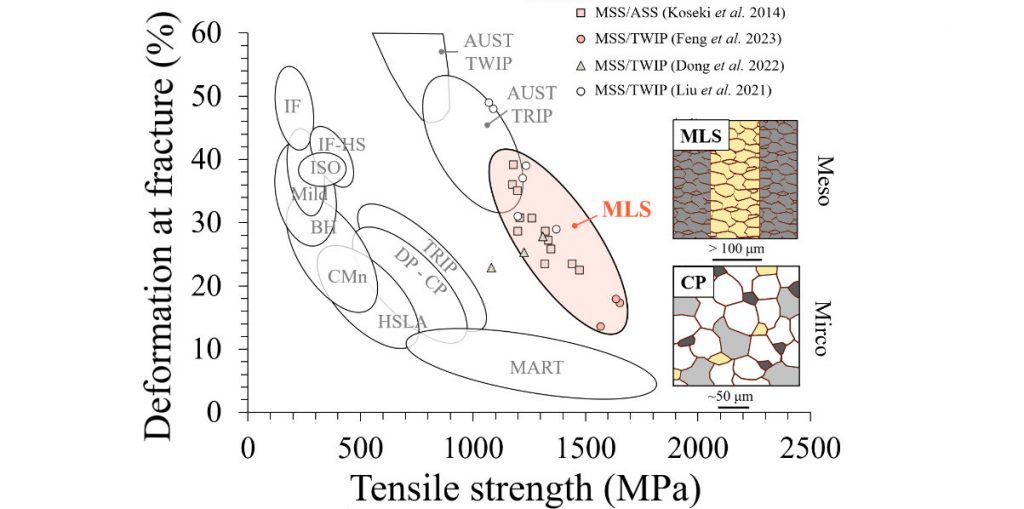
It also discussed the limitations of uniformly distributed microstructures in overcoming the strength-ductility trade-off. The concept of mesostructured steels, exemplified by Damascus Steel and multi-layered composite steels (MLS, typically with a mesostructured scale in the range of 100 µm), was explored. These steels offer a unique property range surpassing other steel families, as depicted in Fig. 31.
Conventional manufacturing of mesostructured steels typically involves roll-bonding different materials into a single structure. However, this process faces limitations in fabricating complex geometrical shapes and can lead to interfacial voids due to severe plastic deformation. Innovative methods, such as ‘direct’ Additive Manufacturing processes including Powder Bed Fusion (PBF) or Directed Energy Deposition (DED), were discussed in the presentation and also the challenges including microstructural control, residual stresses, and powder recycling difficulties (unless one is magnetic and the other is non-magnetic in nature).
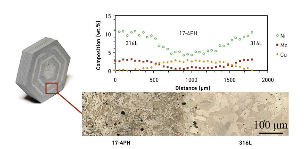
Jiménez-Alumbreros discussed the benefits of processing mesostructured steels using FFF, outlining its associated challenges. The objective of the investigation was to tailor the properties of 316L and 17-4PH stainless steels for multi-material FFF technology (Fig. 32), focusing on optimising process parameters and material performance.
Key considerations for multi-material FFF include powder selection with equivalent particle size distribution to ensure comparable optimal loadings, rheology, and shrinkage. Additionally, the filament fabrication, Additive Manufacturing, and debinding processes must be carefully designed to be compatible with both materials. Sintering, based on criteria such as temperature ranges, densification, and grain sizes, was crucial. Detailed studies on gradient monitoring and control showcased variations in microstructure, phases, composition, and microhardness across the two stainless steel layers, including the interfacial region.
Conclusions drawn from the investigation include successful filament development for FFF, defect-free green part Additive Manufacturing, and tuneable compositional gradients through sintering. Jiménez-Alumbreros suggests further research areas the group is currently exploring, including more detailed sintering studies using dilatometry, controlling shrinkage by adjusting powders and solid loadings, and investigating the effects of mesostructure compositions on mechanical and corrosion properties.
Conclusion
This write-up presents only a small selection of all the interesting presentations that added tremendous value to the conference. It was difficult to pick and choose the papers that have been covered in this report and many presentations that could not be covered for lack of space were also extremely good.
I was unable to cover any presentations on powders and powder production, the majority of the presentations from the students who had excellent research work results in their presentations, software and simulation tools; a couple of hybrid metal AM tooling presentations; a few papers that discussed environmental factors (e.g. includes carbon footprint reduction, mould cleaning and maintenance using dry ice, and hydrogen production at site location).
The table-top exhibitors had short presentations that were dispersed between the regular presentations. These short presentations were very informative and of great value to attendees who were not familiar with the products offered by these companies. The tabletop exhibits also provided an excellent networking opportunity that the attendees were able to take advantage of.
This year, MPIF was able to totally eliminate the COVID-era hybrid conference format. Only one presentation was presented virtually, and that was due to the presenter’s sudden illness. The opportunity to finally have a get-together without the threat of COVID looming overhead was a huge relief for all attendees and will be reflected in the industry at large.
I would like to thank MPIF staff Jim Adams, Bill Edwards, Paul Sedor, and Diane Haggerty for their support. I would also like to thank the presenters for their help with the figures used in this article.
Author
Dr Animesh Bose
CEO
Optimus Alloys
Leesburg, Virginia, USA
[email protected]


