Industry insight from the 2022 International Conference on Injection Molding of Metals, Ceramics and Carbides
In the programme of the 2022 International Conference on Injection Molding of Metals, Ceramics and Carbides (MIM2022), organised by the Metal Powder Industries Federation (MPIF) and held in West Palm Beach, Florida, USA, a number of presentations reported on innovations in both Metal Injection Moulding and the closely related sinter-based Additive Manufacturing process. In this report, Dr Satya Banerjee, Bishoi Consulting Co. LLC, reviews his highlights from the conference programme. [First published in PIM International Vol. 16 No. 2, June 2022 | 15 minute read | View on Issuu | Download PDF]
Johnson and Johnson on medical device challenges for MIM components
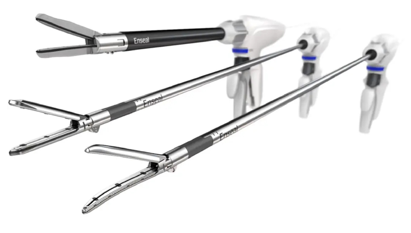
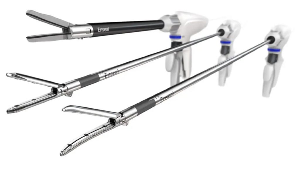
MIM2022’s keynote presentation saw Gary Jaworek, Johnson and Johnson (J&J), New Jersey, USA, speak on the challenges faced in the manufacture of medical devices using Metal Injection Moulding [1]. Johnson and Johnson has a number of divisions which make a wide range of medical products that incorporate MIM components, the production of which are entirely outsourced. These medical products include tools for a range of medical purposes, such as tissue sealing and surgical stapling, and catheters for treating cardiac arrhythmia for surgical application in minimally invasive procedures. Fig. 1 shows a trio of tissue sealing instruments incorporating MIM components.
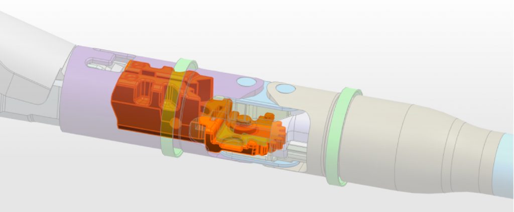
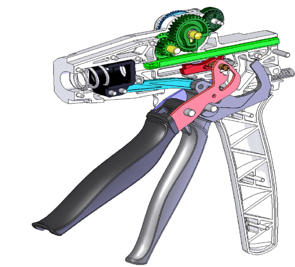
These minimally invasive instruments have MIM applications in articulation joint components, drive components, firing rod connectors, gears, gear boxes, shafts and end effectors. Typical articulation joints inside these instruments are shown in Figs. 2 and 3, with MIM gears inside the control handles visible.
The challenge is that individual medical parts are now becoming smaller than 10 mm and often have non-uniform wall thicknesses and compound surfaces, which makes the location of ejector pins difficult. Features and tolerances are tiny; some parts may be long and only 0.375 mm thick, where flatness is crucial, and all critical requirements must be met. Every available tool must be used to eliminate process risks and ensure these instruments do not fail during use. Naturally, these components must go through the rigid quality and regulatory control procedures that are the norm for medical devices.
Though the MIM process is a very effective method for the production of large quantities of small parts with volumes in the hundreds of thousands, J&J has now recognised that Binder Jetting (BJT) could have distinct advantages over MIM in the medical device arena. The long times required for the mould making and mould qualification processes in MIM could be eliminated from the part manufacturing cycle by turning to BJT. According to Jarowek, this technology will, however, complement MIM in this market.

Animesh Bose compares Binder Jetting and MIM
Animesh Bose, Desktop Metal Inc, Burlington, Massachusetts, USA, presented a comparison of BJT and MIM [2]. Bose stated that while worldwide MIM production may reach a market value of about $4,000 million by 2024, the top ten countries produce around $1 trillion worth of metal parts every year. The market value of metal Additive Manufacturing is just a blip in this $1 trillion world. Until 2015, the thrust of the metal AM industry was in melt-based AM processes, –i.e., Laser Beam or Electron Beam Powder Bed Fusion (PBF-LB/EB) – where each layer of the part is formed by melting powders using a beam of energy, followed by solidification as the beam moves on, creating the part in one step.
This melt and solidify process results in a non-isotropic structure in the part. New developments in powder-binder technologies, however, have led to the decoupling of the part shaping stage and formation of the final solid part, as more and more binder-based AM processes are developed, such as Material Extrusion (MEX), BJT, screen printing and other similar processes. These processes, explained Bose, are similar to the MIM process and can use MIM powders to make isotropic structures. MIM and MEX-based AM processes use a thermoplastic polymer-based binder, while, in BJT, the binder is thermoset. Both MIM and BJT use debinding and sintering to form the final part, but BJT, like other AM processes, does not require any tooling.
Bose stated that in the BJT process, a binder is selectively deposited on a layer of powder to form one layer of the part at a time. The binder forms the bond that holds the particles and layers together. However, the BJT process needs a curing step to provide handling strength to the part and a depowdering step to remove loose powder from the parts before they are moved on to the debinding and sintering stages. After this, the parts may be finished in a similar manner to MIM parts.
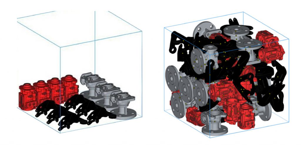
In the Binder Jetting process, the powder itself can support the parts as they are built. The pictures in Fig. 4 show the standard method of additively manufacturing a mixture of parts (left) and a different method of orienting and stacking a mixture of parts to utilise the maximum space in the build box (right). The isotropic properties obtained after sintering are not affected by the orientation of the parts in the build box.
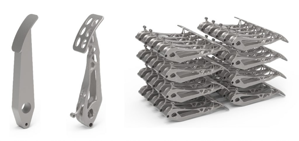
The BJT process also allows the manufacturer to use just the amount of material necessary to perform the function for which the part is designed. On the left of Fig. 5 is an original part design weighing 1.325 kg, while, in the middle, we see the lightweighted, modified BJT design weighing just 0.586 kg. This part would be impossible to produce by MIM. On the right is shown the positioning of a batch of parts in the build box. It is worth noting that BJT can also produce parts much larger than those possible by MIM.
Bose concluded that the BJT process can both be complementary to and serious competition for MIM. Recognising this, many MIM companies are proactively spending money on BJT technology.

Unravelling sintering distortion after machining in the green state
If you take a MIM part and machine a hole in the green state, what would happen to the hole after sintering? This unusual topic was discussed in a presentation by Levi M Rust from ARC Group Worldwide, based in Denver Colorado, USA [3]. Sintered parts are subject to unusual distortions depending on the moulding conditions, and distortions that can occur to holes and slots after the sintering are difficult to predict.
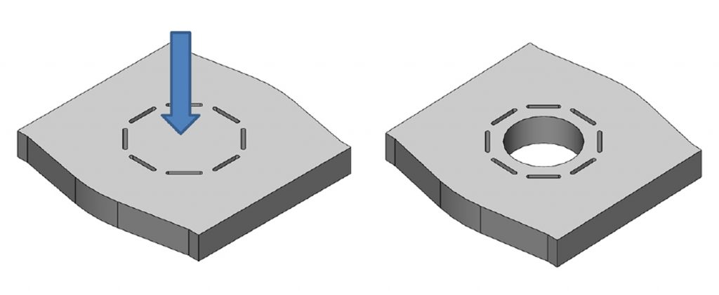
Fig. 6, left, shows an isometric view of a green MIM part with an arrow indicating the gate position. The part has eight slots of the same length, with uniform spacing between them. On the right is shown the part after machining in the green state. The parts in the study presented were made from L605 alloy and, after machining, they were sintered and HIPed to a density of about 9.05 g/ cm3 or 98.3%. Distortions from the machined shape after sintering were measured and attempts made to compensate for the distortion identified by using a different machining pattern in the green state.
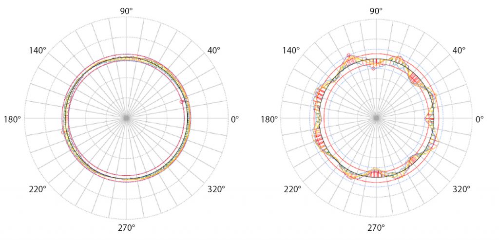
The green parts were machined to an elliptical pattern, based on the overall non-uniform shrinkage in the x and y directions of the part; this resulted in an unusual pattern of distortion. A circular hole resulted in a more uniform type of distortion with a variation of only ± 0.038 mm. Fig. 7, left, shows the measured variations on the machined circle with this variation and on the same hole after sintering and HIPing on the right. This pattern after sintering and HIPing shows a symmetric distortion pattern based on the position of the slots and the openings between the slots.
In the final test, a contoured profile was machined based on the ± 0.038 mm variation measured from the circular hole test. This resulted in an over-correction of the hole by ± 0.020 mm, but a decrease in contoured profile of 0.018 mm.
There are many potential applications for the knowledge gained in this study. These include:
- The ability to achieve near-machined tolerances with materials that are difficult or impossible to machine in the as-sintered state
- The machining of features which would be otherwise impossible to produce using MIM
- A reduction in machining cycle time and tool wear
- The ability to more easily prototype tool changes for tooling modification
Application of hot disc transient plane source for thermal conductivity evaluation in MIM: metal powders case study
Artem Trofimov, from Orton Ceramic Foundation, Westerville, Ohio, USA, presented a novel concept in his paper on the application of a hot disc transient plane source for thermal conductivity evaluation in the MIM industry [4]. Thermal conductivity is a basic material property that changes when there are changes in the material. Thermal conductivity is given by the equation:
λ = α.ρCp
Where:
λ stands for thermal conductivity
α for thermal diffusivity
ρ for the density of the materials
Cp for specific heat capacity
The most common way to measure the specific heat capacity is using differential scanning calorimetry, while the thermal diffusivity is measured by laser flash technique. These methods have sample size restrictions and laser flash, for example, can be used only with solid materials and not powders or liquids. In Orton Ceramic’s study, three individual techniques used for measuring these parameters introduced three measurement errors into the calculated thermal conductivity value.
Orton Ceramic then used a hot disc transient plane source (TPS) method to directly measure the thermal conductivity and thermal diffusivity from a single measurement. The only sample preparation requirement for this method is a flat surface, with minimal restrictions on sample size. This allows the use of this method on powders, binders, feedstock (maybe, with some preparation), green parts, solvent and thermally debound parts, as well as sintered parts. Parts may be tested at temperatures between -196°C and 800°C.
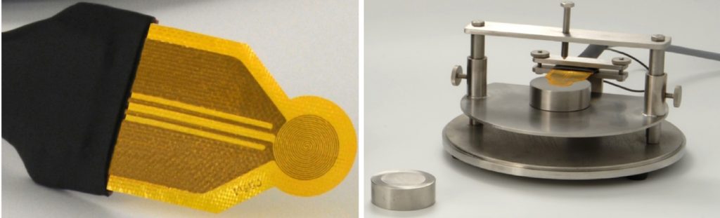
The TPS method uses a nickel double spiral (hot disc) sensor sealed in Kapton films, resulting in a thickness between 60-80 μm. The disc is both the heat source and a dynamic temperature sensor, capable of measurements of thermal conductivity between 0.01-1800 W/m/°K. Measurement times range from a few seconds to a few minutes. Fig. 8 shows a TPS sensor and how it is used on a solid machined metal piece.
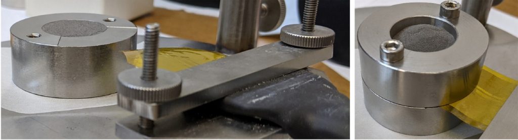
When powder measurements are carried out, the conductivity will change depending on the medium between the powders as well as the shape, size and distribution of the powders. When taking measurements on powders, the powder is first filled in a cylindrical sample holder and levelled off. The TPS sensor is placed on the powder and a second sample holder is placed on top of the first and then filled up with the same powder. Fig. 9 shows a filled bottom sample holder on the left and the two cups filled up with the sensor between the powder on the right.
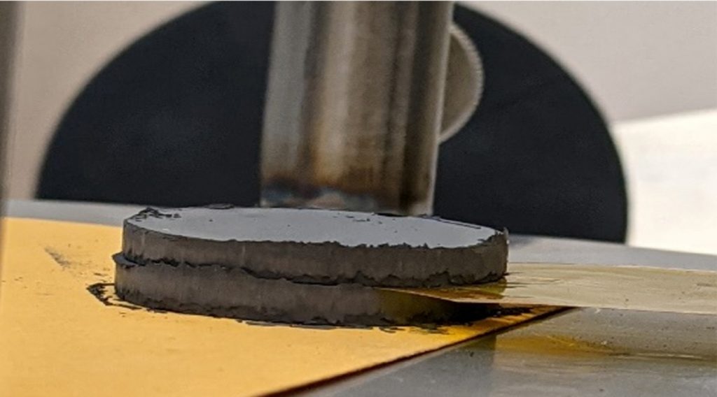
In the case of green parts, two pieces with flat surfaces need to be used. No data were presented on MIM parts, but data on different sizes of powders, and the compacted powders, were presented. This author would expect that, for green MIM or additively manufactured parts made using binders, measurements would have to be carried out in a similar way. Fig. 10 shows the measurement set up, with two discs made with compacted fine powders.
Reducing shrinkage in large stainless steel BJT parts using novel coated metal powders
Alexander Paterson of ExOne (now part of Desktop Metal), North Huntington, Pennsylvania, USA, presented work carried out in collaboration with Tundra Companies, White Bear Lake, Minnesota, USA, to compare the Binder Jetting (BJT) of standard 316L stainless steel with the BJT of stainless steel powder modified by Tundra [5]. Tundra produces a special coating material, TundraKoat, said to improve the packing density of any particulate material to > 80%, which can result in optimised properties for the material. In this case, the partners modified a 316L stainless steel powder, which was used to make parts and rods from which tensile bars were machined.
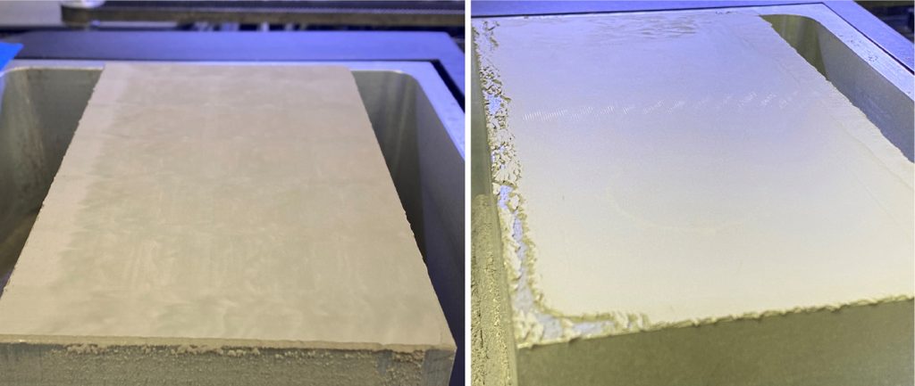
The BJT process used for the standard powder (22 μm) had to be modified to make parts from the Tundra powder. The standard powder is built with a layer thickness of 50 μm, however the Tundra powder, where the particle size was 50 μm had to be additively manufactured with a layer thickness of 75 μm. The change in the layer thickness and powder particle size also caused a change in the binder set time from five seconds for the standard powder to thirty seconds for the Tundra powder. The Tundra powder resulted in a higher packing ratio and compressibility of the powder than the regular powder, which showed a dustier surface. The irregular edges on the build plate for the Tundra powder was a result of the highly cohesive behaviour, which caused shear stresses on the lips of the build box. The printable build space was unaffected. Fig. 11 shows the build surface for the standard powder and the Tundra powder.
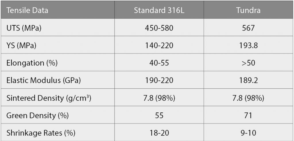
The parts were sintered using a standard 316L profile. Round bars were machined to make the tensile specimen used to obtain the data in Table 1. The Tundra parts showed properties on the higher end of that for the standard powder.
The powder loading for the Tundra powder was 70%, while the standard powder reached 55%. The effect of the low shrinkage is apparent in parts that were 300 mm long, where the Tundra powder resulted in 27 mm less shrinkage because of the higher powder loading.
Production of MIM permanent magnets from recycled NdFeB powder
Rare earth permanent magnets (REPM) are key components for efficient energy conversion for electromobility, green energy, as well as many everyday technologies we can no longer do without, such as smartphones, speakers and more. Only 10% of the REPMs are made in the European Union, with the majority of the remainder coming from China. Furthermore, current mining and manufacturing methods are causing damage to both the environment and the health of people in these areas. Stefan Rathfelder, from the Institute for Precious and Technology Metals at Pforzheim University, Germany, gave a presentation on work being carried out in partnership with Montan University, Austria, on the EU-funded project SUSMAGPRO (Sustainable Recovery, Reprocessing and Reuse of Rare Earth Magnets), which explores the production of permanent magnets using recycled NdFeB powder [6].
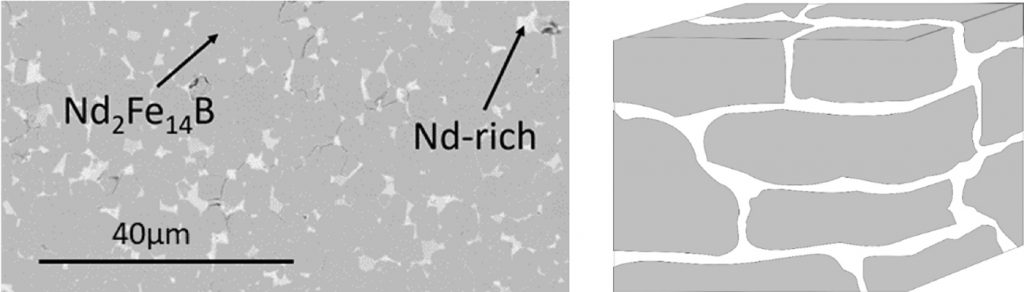
The amount of REPM recycling being carried out at present is only between 1–3%. Challenges faced by recycling are that most REPM-containing products are not designed for recycling and the recovery, and the recycling and reuse of waste electronics lacks attention, so products containing valuable REPMs either end up in landfills or are shredded. SUSMAGPRO would like to create a circular economy by recovery, reprocessing and reuse of REPMs in new products. Their goal is that every fourth REPM used in Europe should be a recycled one by the year 2027. A typical microstructure and the schematic picture of the NdFeB magnet is shown in Fig. 12.
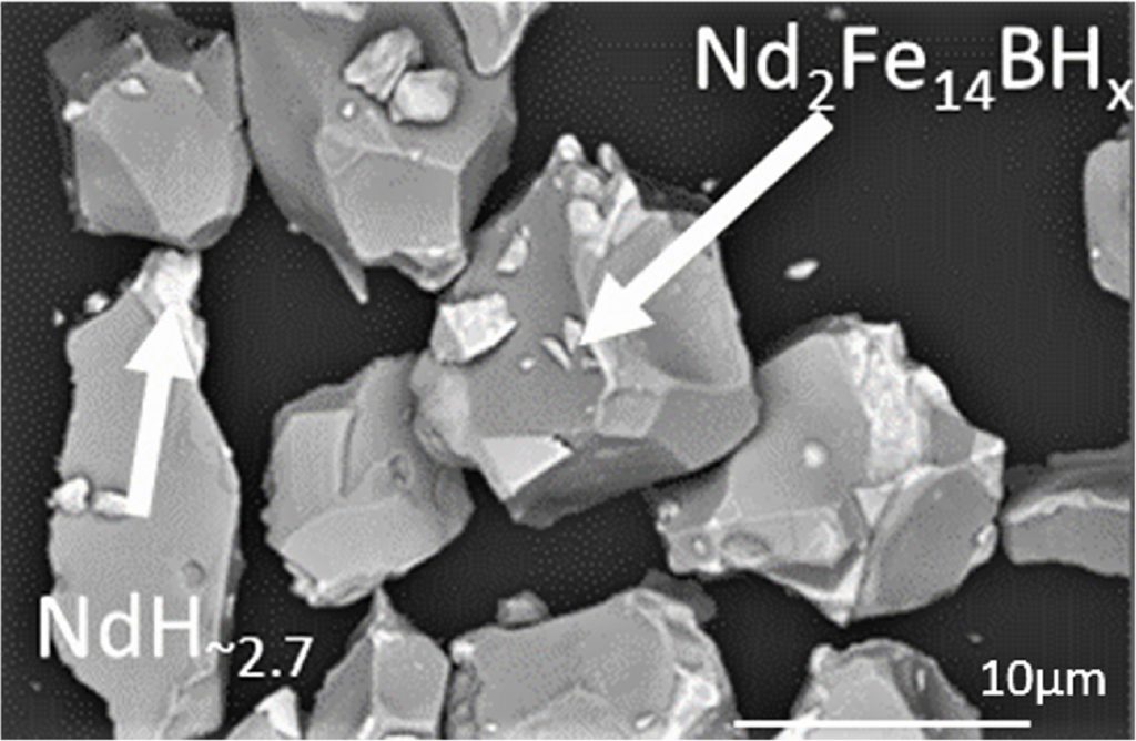
The process of recycling old magnets to produce new ones requires that an end-of-life magnet be decomposed into powder by the Hydrogen Processing of Magnetic Scrap (HPMS) process. During this process, the Nd-rich grain boundary phase forms a hydride, which causes it to expand. The expansion of the grain boundary phase forces the structure to fall apart. After the hydride formation period, the result is a friable, demagnetised powder, comprising a set of Nd2-Fe14-BHx irregular particles that are of the order of 10 μm in size and NdH2.7 particles smaller than 1 μm. Fig. 13 shows a SEM of the powders.
Working with neodymium, however, is complicated by its affinity for oxygen and liability to oxidise quickly. The resulting powder must therefore be coated immediately to prevent oxidation of the powder. After preparing the powder, it was mixed in an extruder with polymeric binders and the resulting feedstock was extruded. Then, an extrusion die was chosen with the desired cross-section. The strand was cut to the desired length and the parts were subsequently debinded and sintered.
Conclusion
This is a report on the selected presentations I found especially interesting after more than the twenty years attending the MIM conference. Limiting myself to a selection, while difficult, was necessary due to the restraints of this format, and does not reflect on the merits of those presentations not reviewed here.It is innovative ideas such as these that make it worthwhile to attend these conferences. My thanks to each of the presenters and to the MPIF for their support in preparing this article.
Author
Satyajit Banerjee PhD
MIM and Binder Assisted Metal 3D Printing Process Engineering
Bishoi Consulting Co. LLC
Winter Haven, Florida, USA
MIM2023
MIM2023 will be held in Costa Mesa, California, USA, from February 27–March 1, 2023.
References
[1] Medical device challenges for MIM and PM components, Gary Jaworek from Johnson and Johnson. As presented at The 2022 International Conference on Injection Molding of Metals, Ceramics and Carbides (MIM2022),February 21–23, 2022.
[2] Comparison of Binder-Jet and MIM, Animesh Bose from Desktop Metals. As presented at The 2022 International Conference on Injection Molding of Metals, Ceramics and Carbides (MIM2022), February 21–23, 2022.
[3] Mitigating post-sintering distortion in MIM via machining in the green state, Levi M Rust from ARC Group. As presented at The 2022 International Conference on Injection Molding of Metals, Ceramics and Carbides (MIM2022), February 21–23, 2022.
[4] Application of hot disk transient plane source for thermal conductivity evaluation during Metal Injection Moulding: Case of metal powders, Artem Trofimov and Thomas McInnerney, from Orton Ceramics. As presented at The 2022 International Conference on Injection Molding of Metals, Ceramics and Carbides (MIM2022), February 21–23, 2022.
[5] Reduction in shrinkage of binder jet printed large stainless-steel parts using novel metal powders, Alexander Paterson and Kyle Myers of ExOne and Adam Bartel and Austin Peters from Tundra Companies. As presented at The 2022 International Conference on Injection Molding of Metals, Ceramics and Carbides (MIM2022), February 21–23, 2022.
[6] Production of permanent magnets from recycled NdFeB powder using the extrusion debonding sintering process, Stefan Rathfelder and Carlo Burkhardt from Pforzheim and Christian Kukla, Santiago Cano Cano and Clemens Holzer from Montan University. As presented at The 2022 International Conference on Injection Molding of Metals, Ceramics and Carbides (MIM2022), February 21–23, 2022,