Comparative study of 17-4 PH spur gears produced by Metal Injection Moulding and Binder Jetting
This study compares 17-4 PH stainless steel spur gears produced by Metal Injection Moulding (MIM) and Binder Jetting (BJT), focusing on dimensional accuracy, microstructure, and mechanical performance. As BJT gains traction in China’s manufacturing sector, the authors – Jie Li, Jimin Xu, and Guangfeng Zhong (Vigor Precision Hardware, Dongguan), alongside Yuder Chao and Yauhung Chiou (You Need Enterprise Consulting, Kunshan) – investigate whether BJT can match the precision and reliability of established MIM processes. The results show that while BJT is effective for early–stage prototyping, MIM offers superior consistency for high–precision components. [First published in Powder Injection Moulding International Vol. 19 No. 3, Autumn 2025 | 10 minute read | View on Issuu | Download PDF]

Binder Jetting (BJT) has been gradually finding its place in the Chinese market since 2020. The patent for Metal Injection Moulding (MIM), in contrast, was first filed in the United States in 1972. Today, MIM has evolved into a leading manufacturing process for small metal components weighing between 0.005 to 500 g. To date, manufacturers in China have produced over 10,000 distinct component designs from 17-4 PH stainless steel via MIM, with some designs manufactured in the billions.
A 2018 report by McKinsey & Company identified metal Additive Manufacturing and MIM as key technologies shaping the future of manufacturing [1]. The survey, involving nearly 100 industry experts, evaluated MIM technology as more mature than metal AM. Since 2011, China has led the world in MIM revenue [2], with major innovative applications developed every two to three years, often replacing conventional processes such as investment casting and die casting.
Recent reports from California suggest that metal components (e.g. hinges and fasteners) in AI servers are being replaced with MIM stainless steel parts, because conventional castings failed due to inclusions and porosity, causing catastrophic failures in simulated Mw 7.0 magnitude earthquake conditions, while MIM parts withstood the test. Additionally, MIM’s capability to produce complex shapes and reduce costs via mass production is expanding into cosmetics packaging.
Interest in BJT has surged since 2017, primarily because the process uses powder similar to that used in MIM, resulting in products close to MIM quality. Its combination of low-temperature shaping and high-temperature sintering has allowed it to encroach on traditional markets such as investment casting and die casting, and even compete with MIM for small-batch production [3].
This research analyses gear components fabricated from 17-4 PH using BJT and MIM, respectively. By evaluating the technical merits and limitations of both processes, the study aims to promote their complementary integration and advance the development of metal powder technologies.
Experimental design
Gear specifications
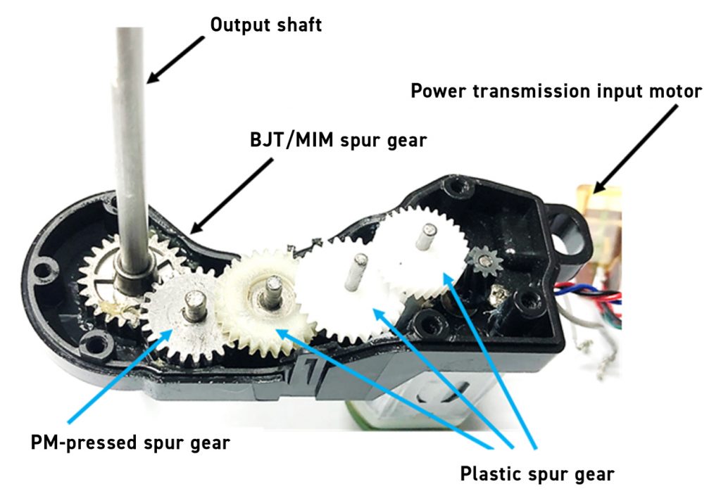
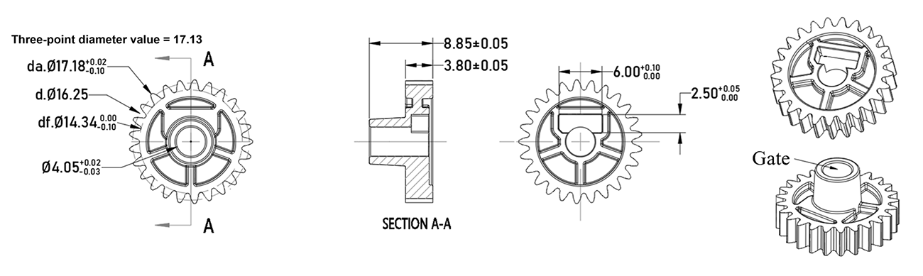
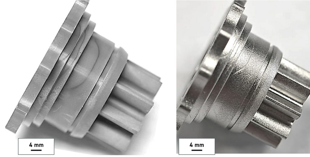
The experiment used the spur gear and stop gear designs in Fig. 1, which were evaluated in actual gearbox assemblies (Fig. 2). The mould adopted a universal linear shrinkage factor (Oversize Shrinkage Factor, or OSF) of 1.165, scaling all dimensions in Fig. 1 [4]. Vigor Precision’s in-house mould centre designed and fabricated the MIM moulds and the MIM and BJT parts.
Powder selection
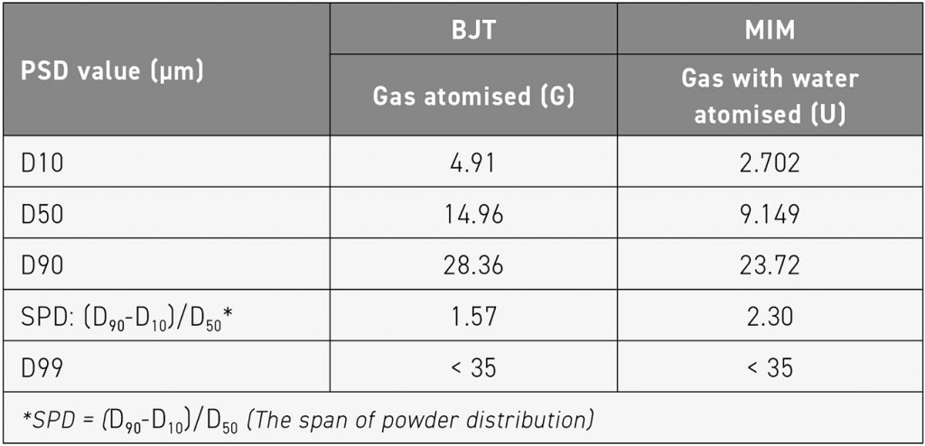
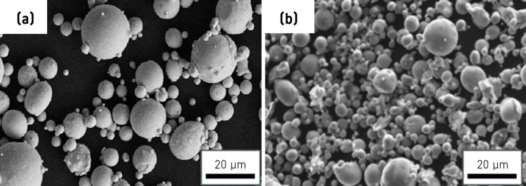
Table 2 lists the two powder specifications used for different processes [5, 6]. Fig. 3 shows their morphologies: BJT uses gas atomised (Gas, G) spherical powder, while MIM uses gas with water atomised (U) irregular powder. The theoretical density of 17-4 PH is 7.80 g/cm3. It is important to note that 17-4 PH is a magnetic alloy powder [7]; thus, its magnetic properties may influence powder behaviour during the build process and should be carefully considered.
Experimental procedures
To confirm post-sintering distortion, BJT used a specific Binder Jetting machine from ExOne, while MIM used mould injection. Table 3 lists the steps and parameters, with all equipment under standard mass production conditions. Parameters were optimised at least three times to meet production standards.
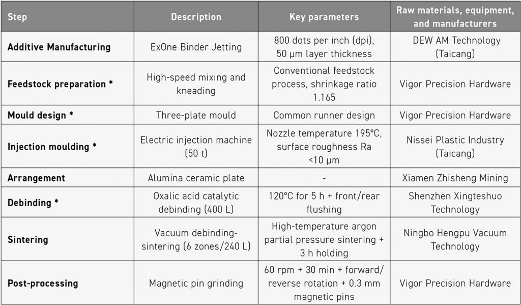
Moldflow analysis optimised the mould for uniform filling, with the MIM feedstock gate at the centre of the bushing to improve gear roundness. Parts were arranged in zones to observe post-sintering geometry. MIM used an oxalic acid debinding furnace at 120°C for six hours, with debinding weight loss verified (weight method and crush method). BJT green parts and MIM debound parts were co-sintered at 1,300°C in a six-zone vacuum furnace, using the same parameters for two batches (>20 parts each) after optimisation. Carbon content testing is performed using a carbon-sulfur analyser to inspect sintered parts.
Post-sintering density was measured via Archimedes’ principle with a microbalance. Samples were vacuum-immersed in water, and cross-sections were polished for pore observation via optical microscopy. Vickers hardness was tested, and microstructures were compared to standard 17-4 PH stainless steels. Surface profiles were measured by MarSurf CD 140, and gear dimensions were checked via a GC-1HP 1211 fully automatic gear measuring instrument, comparing distortion to design values as shown in Table 1 and Fig. 1.
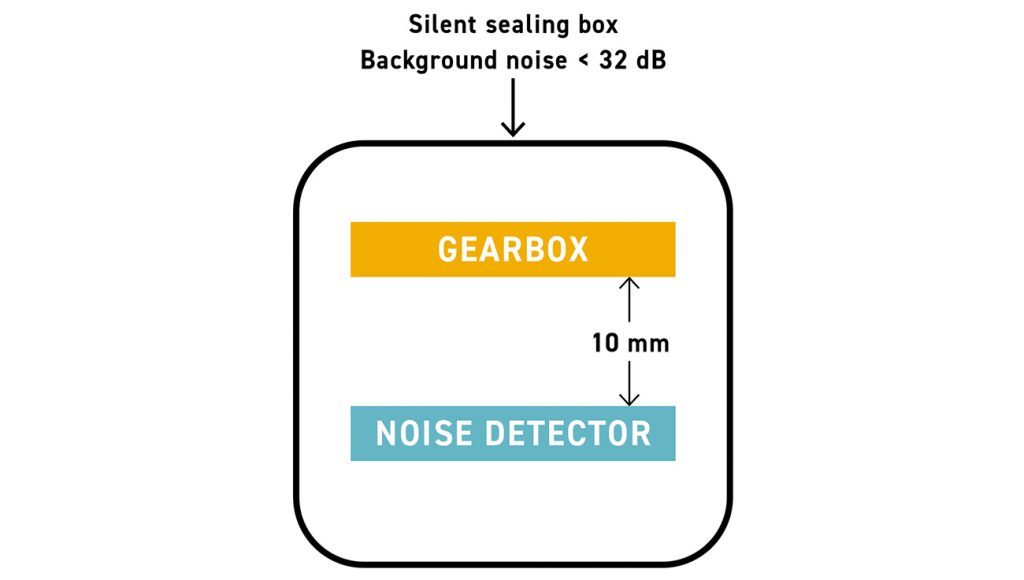
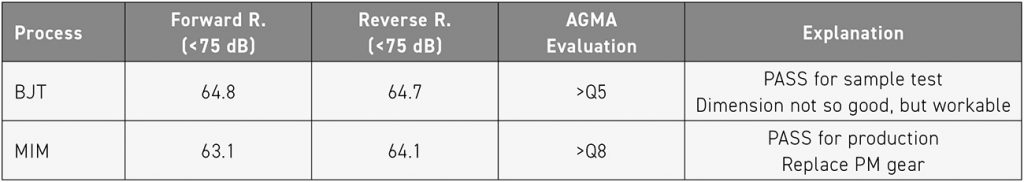
Finally, a simplified gear transmission noise test was conducted, shown in Fig. 4. The input fixed torque and rotation speed were enabled to record the noise values during the transmission process. The MIM gear was used as the output end, and the comparison before and after processing was carried out to assist in evaluating the transmission effects of BJT and MIM. Following the noise test, gear accuracy ratings were performed to assess compliance with American Gear Manufacturers Association (AGMA) standards.
Results
Basic physical properties
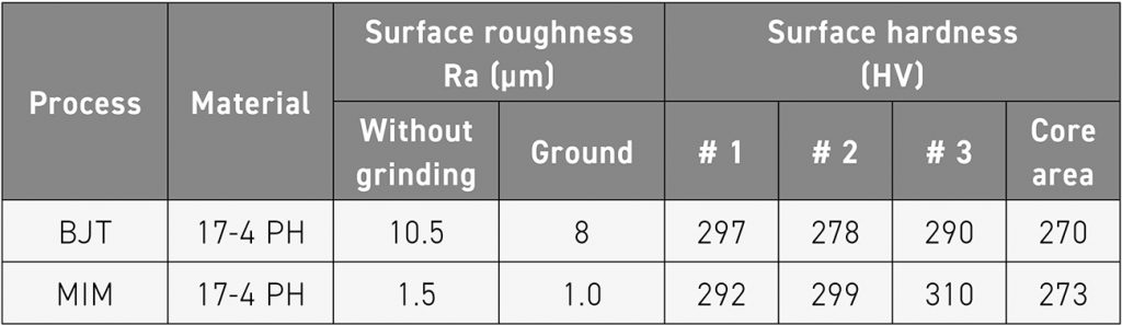
After sintering, both BJT and MIM products underwent moderate surface magnetic pin grinding and sandpaper grinding to 2000 grit for flatness. As shown in Table 4, tooth surface roughness and hardness were tested, showing results comparable to standard MIM parts. Therefore, the optimised sintering temperature resulted in the appearance and surface profile of the gear products as shown in Fig. 5.
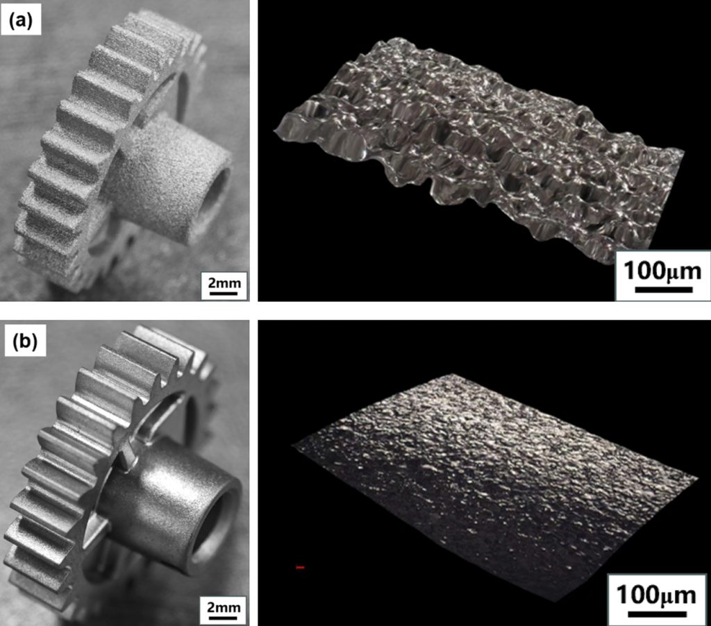
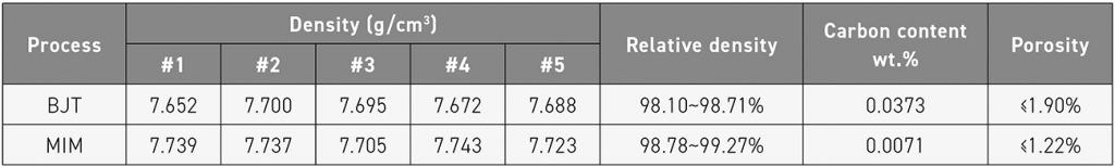
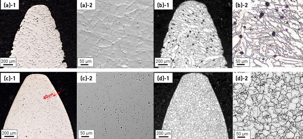
Table 5 and Fig. 6 present the post-sintering pore characteristics and density measurements. Cross-sections of the gear teeth were polished and analysed by optical microscopy, revealing that BJT parts had a lower relative density (98.10-98.71%) and higher porosity (≤1.90%) compared to MIM parts (98.78–99.27% relative density; ≤1.22% porosity). As shown in Fig. 6, the BJT samples exhibited uneven pore distribution and larger pores throughout the profile, while MIM samples displayed a dense outer contour (~40 μm) and finer, more homogenous microstructures.
Precision of tooth diameter and base tangent length
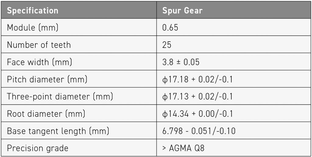
Due to the tooth design, calliper measurement is inherently difficult. Fig. 7 presents tooth diameter measurements for ten BJT and ten MIM samples, both before and after surface grinding (BG: before grinding; G: ground). The results reveal significantly greater dimensional variation in BJT parts, with many values falling outside the specified tolerance range of ϕ17.13 +0.02/-0.1 mm (as defined in Table 1). This deviation is attributed to lower forming pressure and anisotropic shrinkage during the BJT process.
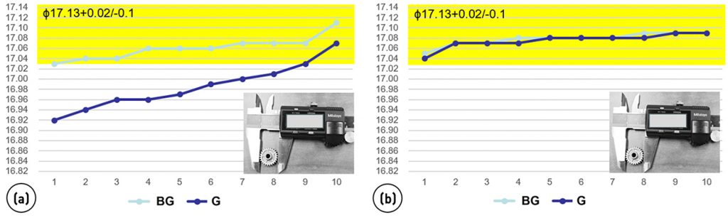
Fig. 8 shows twenty-five-point measurements of three BJT and three MIM gear samples, evaluating two key metrics: the tooth outer diameters (top row) and base tangent lengths (bottom row). Each data set includes values recorded both before and after grinding (BG: before grinding; G: ground). The acceptable tolerance bands (ϕ17.13 + 0.02/–0.1mm for diameter and 6.798 –0.051/–0.1 mm for base tangent length) are indicated in yellow. Results show that BJT parts exhibited consistently wider scatter and deviation from specification, primarily due to the process’ low build pressure (0.1–0.2 MPa) and directional shrinkage effects, in contrast to MIM’s stable high-pressure injection (>50 MPa).
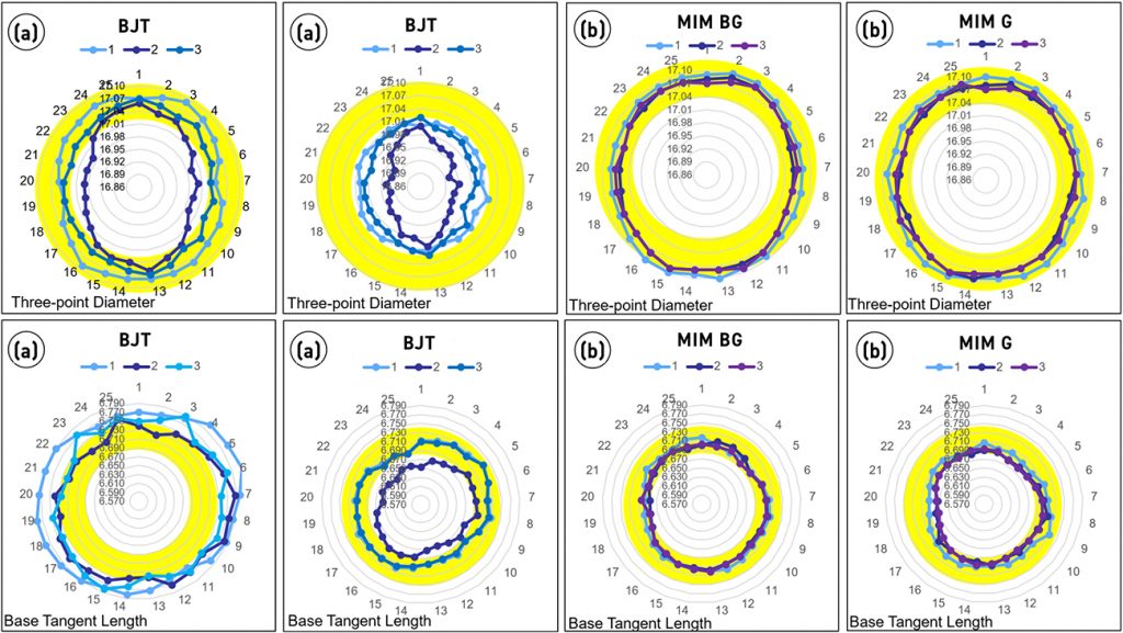
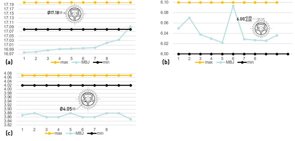
Fig. 9 shows dimensional measurements of ten BJT gear samples across six critical specifications. Notably, the tooth diameter (a) and groove width (b) display the greatest variation, suggesting process-related inconsistency in powder packing and sintering. In contrast, the central hole diameter (c) showed relatively stable dimensions. These parts, along with their MIM counterparts, were assembled into gearboxes for functional evaluation. Under no-load conditions, average transmission noise was measured, with all values being below 75 dB (Table 6).
Discussion and analysis
This study focuses on identifying process limitations in industrial applications, with particular attention to dimensional precision and microstructural consistency.
Evaluation of BJT gear products
BJT gear accuracy was limited by build resolution and sintering distortion. Despite the use of 800 dots per inch (dpi) and 50 μm layer thickness (adjusted to 932 dpi and 42.9 μm after shrinkage), the process could not consistently achieve the tighter dimensional tolerances seen in MIM parts.
Even with MIM-grade PSD and highly spherical gas atomised powder to minimise X–Y directional variation, BJT remained sensitive to powder packing inconsistencies, resulting in dimensional deviations. In the current AM industry, a conventional layer thickness is 50 μm.
The BJT process in this study employs a patented high roller pressure during powder spreading [8], which enhances green part packing density. The binder content is only ~10% by volume, permeating only between powder particles. Binder Jetting machines typically have a spreading pressure far lower than MIM injection/holding pressures. This low-forming pressure allows powder particles, particularly magnetic 17-4 PH, to reorient and agglomerate during spreading. Magnetic-induced agglomeration hinders residual carbon escape during sintering, as carbon originates from both the binder and powder itself.
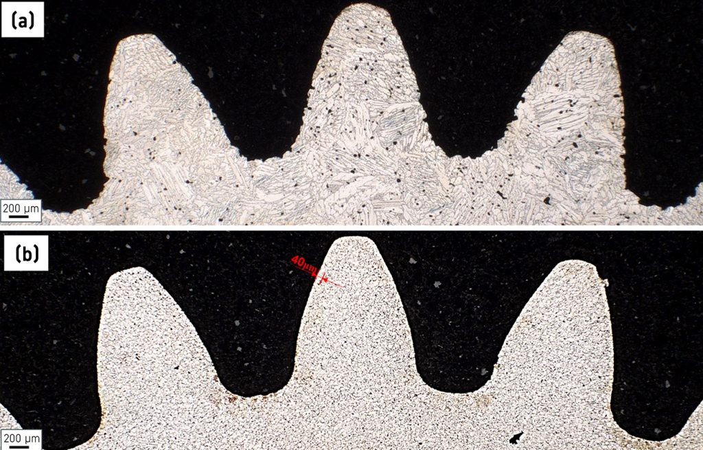
This causes abnormal grain growth in BJT parts at high temperatures. As shown in Fig. 10, etched micrographs of BJT and MIM gears reveal distinct grain structures: BJT shows large columnar grains, while MIM maintains mostly equiaxed grains with a distinct ~40 μm dense layer near the contour. Unlike MIM’s two-step debinding that completely removes the binder, AM (even material extrusion) may leave residual binder transformed into carbon, causing abnormal grain coarsening [9]. Such inhomogeneous microstructures can be mitigated by subsequent heat treatment.
Currently, Binder Jetting machines on the market often still operate under normal atmospheric pressure or a slight protective atmosphere (1.2 atm). Even with the pressure roller powder spreading mechanism used in this study, it is difficult to make the green compact denser with the assistance of such pressure. Therefore, it is more likely to have pores caused by large powder stacking defects, especially the roughness at the edge of the part surface, which is just the opposite of the situation in MIM, where the surface is highly dense but there are pores inside.
Therefore, based on previous measurements by pore observation and dimension inspection, it is very difficult to produce a precise gear product with only one build attempt. Of course, process capability can be improved with more attempts, but one challenge is that variations can be found in parts built at the same time in another location in the build box. These findings suggest that Binder Jetting may currently be unsuitable for producing small gears requiring high structural precision, particularly in multi-layer builds. Although it can quickly build similar features and have basic functions, it cannot be applied to scenarios with tight tolerances. Given the current state of irregular divergence, more research is needed in BJT to find better compensation methods and measures, rather than relying on post-processing or correction to achieve mass production.
Evaluation of MIM gear products
MIM has inherent limitations, including isolated pores influenced by coarse particles in the D90–D99 range, as well as process-dependent defects in complex features. A typical example is the ‘black mark’ defect (Fig. 11), which arises when feedstock experiences high shear or abrupt mould transitions, leading to powder–binder separation. After sintering, this can result in shallow, sunken lines on the part surface. While such defects may be visually noticeable, they are often acceptable if functional testing is passed and the affected areas are covered or non-critical in assembly.
In MIM, the binder accounts for a high-volume fraction (approximately 35 vol.% in the OSF 1.165 state of this study). A nearly uniform-thickness binder layer separates powder particles. After primary debinding, numerous fine interconnected pores and skeleton binder supports remain. During secondary debinding, residual skeleton binders are gradually removed, pulling powder particles closer. In the middle sintering stage, interconnected pores collapse during rapid densification, forming isolated pores. In the late sintering stage, accelerated grain boundary migration forces some pores to detach from grain boundaries and become trapped within grains, as observed in the metallography of Fig. 6.
After nearly half a century of research and practical application, MIM has indeed proven capable of efficiently producing precision parts using injection moulding dies and equipment under proper constraints (powder particle size D99<40 μm). For components within 30 mm, dimensional results align with Archimedes’ principle calculations and can be effectively corrected by adjusting process parameters at various stages. More importantly, after engineering discussions to resolve defects, MIM enables rapid ramp-up to mass production, matching the unique characteristics of electronics industry orders (fashion-driven, short-term volume demands). This explains its widespread adoption in electronic products.
Additional considerations for BJT and MIM
In this study, both processes exhibited anisotropic shrinkage, with larger errors in the X and Y axes, while dimensional accuracy and shrinkage rate in the Z axis were more precise. BJT’s dimensional accuracy was significantly lower than MIM due to layer resolution and powder stacking direction. However, BJT enables rapid prototyping without expensive, time-consuming moulds. Its low-temperature AM offers fast forming and minimal deformation, making it indispensable for early-stage part research and development. BJT uses highly spherical powder free of satellites, achieving a sintered density approaching that of MIM. Although transmission parts like precision gears with functional surface requirements show larger error fluctuations, BJT still meets basic transmission needs and retains advantages over other rapid prototyping processes. Regrettably, limited R&D funding prevented more BJT tests with higher resolution and smaller layer thickness (25 μm) from being conducted. Table 7 summarises the process comparison for industry reference.
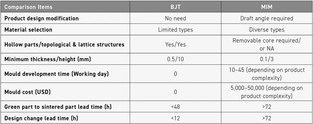
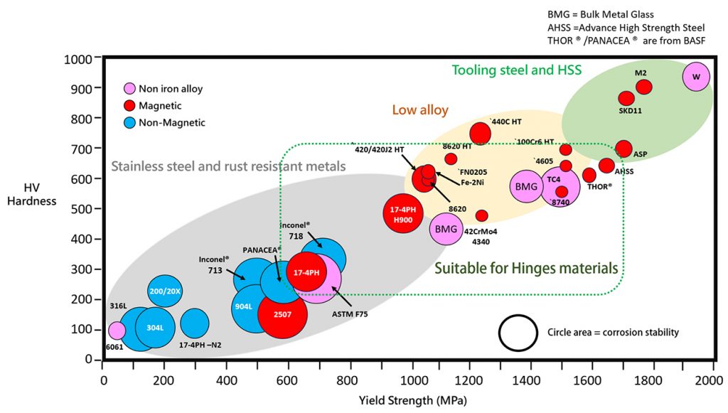
Fig. 12 presents a diagram showing the relationship between hardness and yield strength of BJT and MIM materials, originally provided on the BASF AG website and modified by the author of this study [10]. Regardless of whether it is the BJT or MIM process, 17-4 PH has become the most frequently used material in powder forming technology. It features adjustable hardness levels, and, through low-temperature precipitation hardening heat treatment, copper can be precipitated and dispersed within the stainless steel matrix to achieve strengthening. Additionally, it exhibits very low deformation, is easily sintered within the range of 1,300 ± 30°C, and its numerous advantages have made it a widely popular material.
Conclusions
Spur gears made from precipitation hardening stainless steel 17-4 PH were produced using Binder Jetting and Metal Injection Moulding, enabling a comparative assessment of the two processes.
BJT uses highly spherical powder without satellite particles, achieving a sintered density that is approaching that of MIM products. Although transmission parts like precision gears with functional surfaces exhibit greater dimensional variation and dispersion, BJT still meets basic transmission requirements and retains advantages over other rapid prototyping techniques.
MIM, by contrast, benefited from established dimensional stability and microstructure benefits from moulds and injection machines, which ensure uniform green part formation under high injection pressure. Sintered MIM components exhibited local non-critical defects and superior microstructural consistency.
BJT samples, while promising, showed microstructural issues related to low-pressure powder deposition. Local agglomerates of iron-based powders impeded carbon removal during debinding and led to abnormal grain growth during sintering. Post-sintering heat treatment can mitigate these effects and improve performance.
MIM gears exceeded AGMA Q8 standards, while BJT gears reached only AGMA Q5, underlining the latter’s current limitations in precision.
Future potential
It is important to note that the BJT findings are based on a single manufacturing run. Due to limited manufacturing experience, factors such as the powder spreading direction of parts, the number of built layers, and the placement relationship in the sintering furnace were not as refined as those in established MIM production environments. With further AI optimisation and process control, Binder Jetting has the potential to complement Metal Injection Moulding in early-stage prototyping and customised gear production.
Authors
Jie Li, Jimin Xu and Guangfeng Zhong
Vigor Precision Hardware and Plastic Products Co., Ltd., Dongguan, China
Yuder Chao and Yauhung Chiou (Dr Q)
You Need Enterprise Consulting Co., Ltd.
Kunshan, China
Contact
Chiou Yau Hung (Dr Q)
[email protected]
Jie Li
[email protected]
www.vigorprecisiongear.com
Vigor Precision Hardware and Plastic Products Co., Ltd.
Units A1, A4–A8, 8/F, Block A, Texaco Industrial Centre,
256–264 Texaco Road, Tsuen Wan, New Territories, Hong Kong
References
[1] Sheppard, Ben, et al., ‘Factory of the Future Issue One: Advanced manufacturing technologies,including 3-D printing, will disrupt how we manufacture. Are you ready to implement them?’, Operations Practice, McKinsey & Company, 2014
[2] Chiou, Yau Hung. ‘Redefining device design: the role of Metal Injection Moulding in consumer electronics hinge mechanisms’, PIM International, 2025. 19(2) pp. 75-82
[3] Aust, E, et al. ‘Advanced TiAl6Nb7 bone screw implant fabricated by metal injection molding’, Advanced Engineering Materials, 2006;8, pp. 365–370
[4] Chiou, Yau Hung. ‘The math in the magic: Calculating the sintering shrinkage of MIM parts’, PIM International, 2022, 16(2), pp. 97-101
[5] German, Randall. ‘MIM 17-4 PH Stainless Steel: Processing, Properties, and Best Practice’, PIM International, 2018, 12(2), pp. 49-76
[6] Bai, Yun, et al., ‘Effect of Particle Size Distribution on Powder Packing and Sintering in Binder Jetting Additive Manufacturing of Metals’, Journal of Manufacturing Science and Engineering, Aug 2017, 139(8), 081019
[7] Stashkov, Alexey, et al. ‘Magnetic and electric properties, and hardness of 17-4 PH stainless steel fabricated by selective laser melting’, Journal of Physics: Conference Series, Nov 2019, 1389(1), 012124
[8] Rishmawi, Issa, et al. ‘Tailoring green and sintered density of pure iron parts using binder jetting Additive Manufacturing’, Additive Manufacturing, 2018, 24, pp. 508-520
[9] Go, Ara, et al. ‘Fabrication of 17-4 PH stainless steel by metal material extrusion: Effects of process parameters and heat treatment on physical properties’, Materials & Design, Dec 2024, 248, 113471
[10] BASF AG, ‘Product portfolio’, Accessible at: https://electronics-electric.basf.com/content/basf/electronics-electric/global/en/electronics/metal_systems/catamold/who-we-are/product-portfolio