A tooling expert’s ‘primer’ on Metal Injection Molding: What technology newcomers need to know
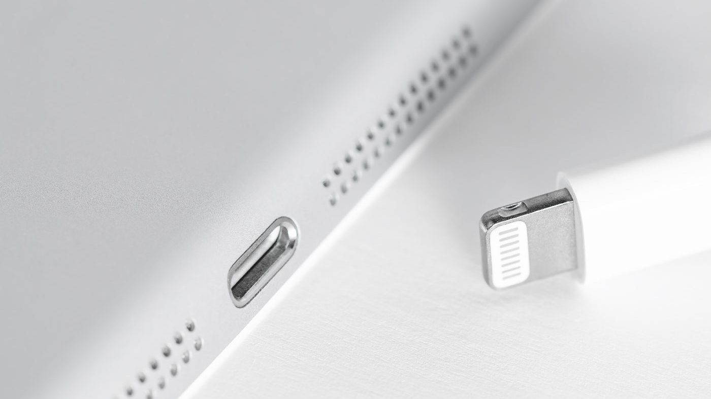
Metal Injection Moulding often has an aura of mystery around it. Whilst those in the industry understand the technology well, there are many ‘on the outside’ who are more apprehensive. In this article, Declan Coyle takes some of the mystery out of MIM technology in relation to tooling. Having gone through his own ‘MIM initiation’ process when tasked with developing the tooling for Apple’s Lightning connector in 2011, Coyle is well-positioned to offer some practical ‘do and don’t’ suggestions from a tooling engineer’s perspective. [First published in PIM International Vol. 18 No. 2, Summer 2024 | 15 minute read | View on Issuu | Download PDF]
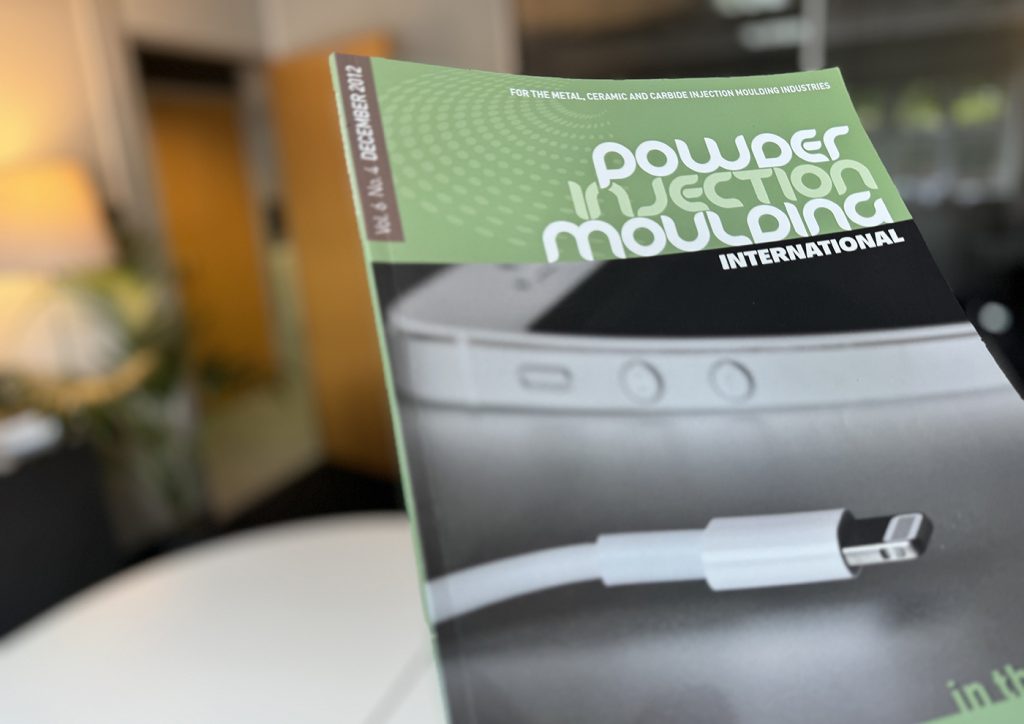
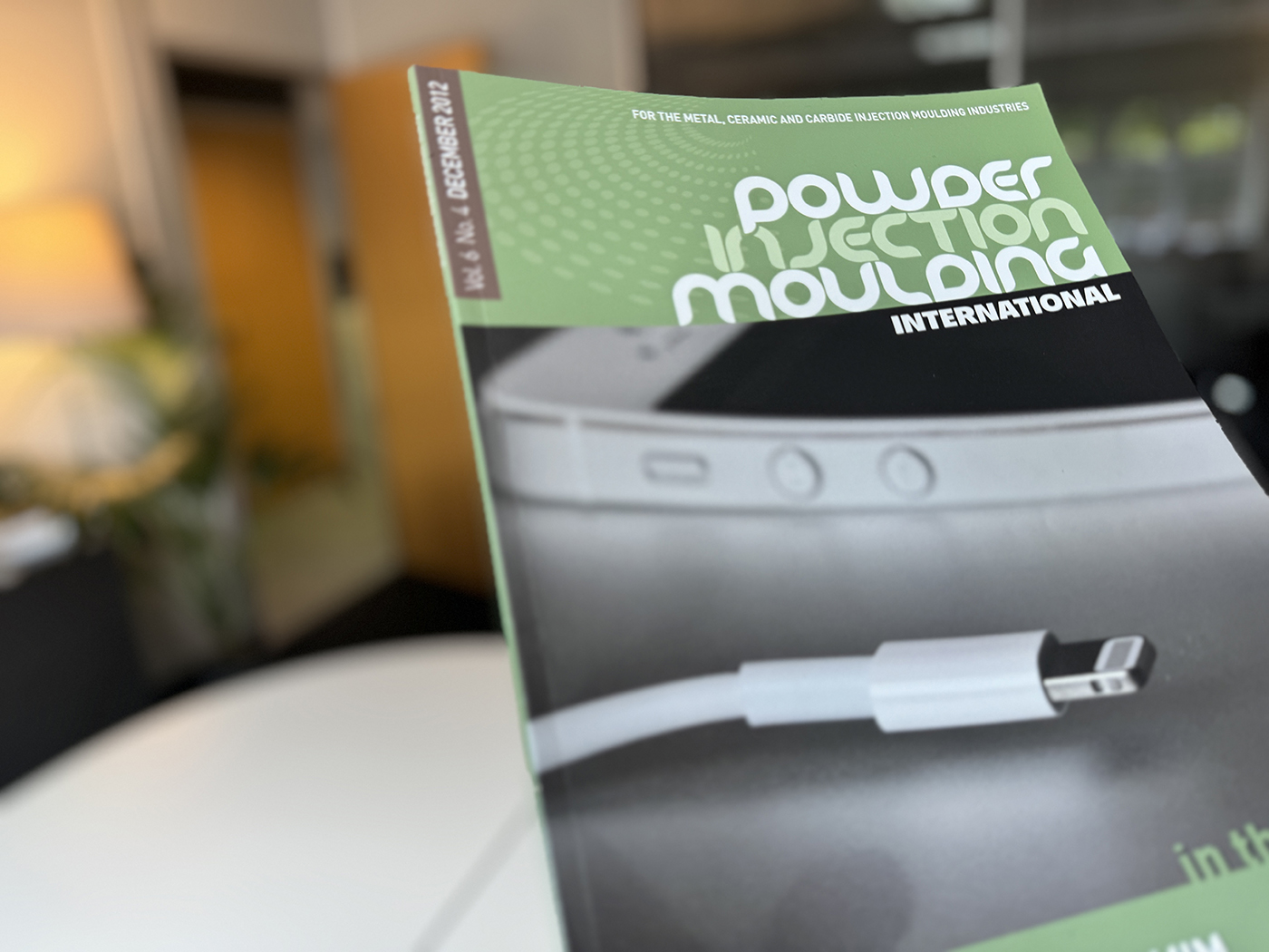
I have a small confession to make: I still have a copy of PIM International from December 2012. Why? Because this issue had the newly-unveiled Apple Lightning connector on the front cover. And that little connector owned most of my life for a solid eighteen months. It was my introduction to Metal Injection Moulding, the application which taught me about MIM from the bottom up. A true baptism of fire.
I’ll give a little more background to my introduction to the technology back in 2011: I was a new tooling engineer at Apple. My history included a mix of manufacturing experiences that helped me get involved in a variety of tooling flavours. I was eager to learn and grow, so I volunteered for the offbeat stuff as much as possible.
One day, my boss approached my desk and asked me to join him for a five minute catch-up. At the end, he said, “Oh yeah, that reminds me. We have a MIM part coming that may interest you. Sound good? Away you go, have fun, figure it out, and help make this happen.”
And that’s how I got the chance to dive into the deep end of Metal Injection Moulding: on an application that ended up with a production run of billions and, in the process, reshaped an industry.
Building the building blocks
You may be wondering how I approached this mammoth task. What did I do to start my MIM journey? A few of you may even be wondering how you can start on your own MIM journey.
Well, I started by reaching out to people with MIM experience within Apple, I ordered all the books on the science and application of the technology, and I jumped on a few planes to visit MIM vendors. I asked lots of questions – hundreds of questions. These included:
- What are the most important MIM-related things to know and appreciate as a tooling engineer?
- What makes MIM different from regular injection moulding?
- Do you do anything special with your MIM tool design?
- What else do I need to know?
- How can I be a better tooling engineer for a MIM programme?
- What do I need to know about material preparation?
- How does the raw material affect part quality?
- Does the material need to be dried?
- How does moulding quality affect what happens after moulding?
- What problems do you suffer from most, and what causes these issues?
With the support of many colleagues and industry professionals, I eventually learned a bit about MIM technology and its application. It’s a magical technology; I still find it hard to believe that it actually works. Now, I want to guide you through these lessons and take some of the mystery out of MIM technology in relation to tooling.
My goal here is for you to take away some practical ‘do and don’t’ suggestions from a tooling engineer’s perspective. We won’t get too entangled in specific materials or go too deep into sintering science – you can do a deep dive into the aspects that interest you another time. Instead, we’ll chat about overarching concepts, hints and actions that will be useful in all MIM settings. Are you ready? Let’s do this.

Why MIM?
Why does anyone use MIM? It’s used to reduce machining time and to create unmachinable geometries. Add the possibility of high-volume production to these two reasons and you can see the obvious economic advantages.
A good place to start our MIM story is with the terms that had me scratching my head way back in 2011. All of these descriptive terms are standard for everyone in MIM, but they shouldn’t be a barrier to newcomers:
- Brown part
- Green part
- Final part
- Debinding
- Sintering
- Sintering fixtures
- Re-striking

What does all this mean? Well, let’s take a quick look at the basic manufacturing cycle of a typical MIM part. Fig. 3 shows the basic steps: feedstock (raw material pellets) > green part > brown part > final part. The main operation transitions to focus on are:
1. Moulding
Injection moulding the feedstock, which produces the green part.
2. Debinding
Melt away the ‘polymer’ binder material, which produces the brown part. Debinding will take place at ~500°C.
3. Sintering
High-temperature ‘baking’ to ‘melt’ the porous part into a solid metal component. Note that the sintered part is ~20% smaller than the brown part. Sintering takes place at around 1,200°C for stainless steels (Fig. 4).

Some thoughts on binders: there are many different types of binder, but the typical makeup is a combination of polymer, wax and other materials. Binders are designed so that around 90% can be removed in the debinding stage, while 10% remains to hold the brown part together ahead of sintering (Fig. 5). This 10% is known as the ‘backbone binder.’

Prototype tooling
All tooling and moulding journeys begin with the prototyping, or the ‘proto’, stage. What’s the best way to approach MIM proto tooling? You may be tempted to do the business-as-usual approach: “Let’s play it safe and make a one -or two-cavity proto tool.” Sounds reasonable, right? First, though, ask yourself: Is this a missed opportunity? What extra value can you get from prototyping?
Why not build a four- or eight-cavity tool as well as a simple single or double cavity tool? Even if the CAD part design is 75% complete and still needs lots of work. Be brave. Make the tool with the current CAD maturity. The comparison data between two cavities and eight cavities will teach you a lot.
Imagine the following scenario: you have created the perfect two-cavity tool. Parts look amazing, dimensions are within tolerance. Everyone is delighted with the cosmetic quality. High fives all-around! And then you discover the whole process falls apart when you add more cavities. This can be a real spanner in the works.
Instead, you can use proto tooling to find and push a few limitations. Like all injection moulding, you have an open opportunity to approach proto with a sense of exploration. Take some risks. I can tell you, it’s mentally liberating to look at proto tooling as a throwaway. Tell yourself that this tool is not going beyond proto. Instead, squeeze every single drop of learning and data from this tool. That’s the best attitude to have.
Sometimes, however, engineering teams are under pressure to make use of the proto tool in the next stage of development, but be careful. This may limit your design and part performance optimisation and lock you into a safe bet that may not be the best option.

MIM vs regular injection moulding
What are the first things I think of when comparing MIM to regular injection moulding? Well, MIM really is a stand-alone technology, so my list is a bit long. Here goes:
- Material separation
- Material preparation
- Feed system
- The moulding process
- Sintering fixtures
- Restrike
- Tool maintenance
- Machining after sintering
Let’s dig into each one of these with a bit more detail. As POM is one of the most popular binder materials, we’ll use it as a binder stand-in here. POM stands for polyoxymethylene, and its use was commercialised by BASF SE with its Catamold brand of feedstock. POM-based systems are now available from pretty much all binder and feedstock suppliers.
1. Material separation
Hesitation and pressure drop are things that we watch for in regular injection moulding. It can cause bad welds, trapped air, and difficult-to-solve cosmetic issues in plastic parts. Hesitation and pressure drop in MIM have a bigger and less forgiving impact. Why? It creates metal-binder separation. Metal gets left behind in situations where the wall section decreases abruptly, whilst it’s easier for the polymer binder to keep flowing forward.
Imagine a mixture of honey and golf balls. Yes, this sounds messy, but bear with me for a few seconds. In your mind’s eye, put the honey and balls in a bowl. Now give it a good mix. You have just created a proxy for MIM material when heated to moulding temperature (~200°C). In this example, the golf balls represent the metal and the honey is the binder material (Fig. 6).

This mixture flows freely and in partnership when the part wall section is big enough for the golf balls (metal powder) to move freely. That all changes when things get a bit restrictive. If the flow path becomes cramped, the honey finds it easier to continue flowing ahead. Is this mental picture working for you? The honey will glide through the restrictive area. “See ya later golf balls. Gotta keep moving. We’re outta here.” You get the idea.
The metal powder and binder in MIM behave in a similar fashion during moulding, splitting from each other when the going gets tough. This phenomenon can create areas in your part that are binder-rich and a bit low on metal.
And why does this restriction and separation matter, you ask? Well, as you risk getting a part with areas that are binder-rich and metal-poor, mechanical properties can be affected as well as cosmetic issues appearing. So what can you do? Better manage your wall section transitions. MIM does not like sudden changes in wall sections or tight geometry transitions, so give your wall section transitions a generous ramp lead-in. Be generous with radii. Radii help with flow and give the MIM material an extra few microseconds to react more positively.
2. Material preparation
Material consistency is a critical first step. It’s super, super important in MIM. If you get this step wrong, all other steps will have issues. It’s even more important than getting material preparation right in regular injection moulding. So what do you need to focus on in material preparation?
- Homogeneity
- Dust control
- Pellet size control
- Contamination management
Most MIM parts are likely to have a set percentage of reused material. Material from runners and badly moulded parts gets re-compounded back into pellets. This recycled material is then added to virgin material at a specific percentage, dispersed evenly by a mixer.
This material needs to be sieved after mixing. Why? The mixing creates extra dust and smaller pellets. You have to remove the dust from your feedstock before moulding.

3. Feed system
You may notice that the gating area of your part is sometimes much darker than the surrounding area. So why does this happen? Because the darker area has a higher metal powder concentration. The material flowed through the runner and then came to the gate restriction. The binder material said, “See ya later,” and flowed ahead. That’s why you get a metal concentration at the gate area (Fig. 7).

But is there anything you can do to avoid this? If you are using a hot runner system, try to land the feed on a mini runner outside of the part. Why? There will be a concentration of metal-rich material at the machine nozzle and hot runner tip. This happens on each cycle as you get material in these areas waiting for the next injection.
Whilst metal-rich areas may be perfectly fine from a mechanical performance perspective, the cosmetic challenges they present are called discolouration. In the end, the criticality of this depends on the cosmetic requirements of your part and the surface finishing specification; if you’re blasting and plating, discolouration will not be an issue.
4. The moulding process
As stated, one of the most popular binder materials is POM. Here’s something to think about if you are moulding this type of material; hopefully it will help you progress without getting stalled with MIM technicalities too early.
Forget about the metal component of the feedstock for a while. Treat the material as if it’s plastic only. This will get you 85% through tool design and process considerations. You will need to make some adjustments to get the last 10-15% of MIM-specific optimisation.
Most people assume that as MIM feedstock is rich in metal it is super aggressive, wearing down everything it comes in contact with: a merciless grinding material. In fact, the opposite is closer to the truth: the binder ensures that your barrel, nozzle and tool steel get practically zero metal-to-metal engagement. MIM materials mould easier than you may expect.
5. Sintering fixtures
Your first question: what is a sintering fixture? It’s a shaped support on which you place your parts before putting them on a tray and into the sintering furnace. Fixtures hold and control parts whilst they are getting ‘cooked’ at 1,200°C and, as such, they are made from heat-resistant materials like ceramic and molybdenum.
Here’s a mental model I found helpful when designing sintering fixtures: Think of a part as hot, cookedpasta strips. At 1,200°C, the part will fall, collapse, and distort. Thinking of pasta helps you visualise and minimise warpage in advance, informing your fixture design and helping you think ahead to restrike.

First, focus on the biggest flat surface; this will be the master surface. It is common to put this in direct contact with the fixture. Features that are likely to sag and warp will require some support. The top part in Fig. 8 represents this type of scenario.
6. Restrike
Here’s a simple truth that will liberate you as you take on a MIM project: things are going to bend and twist during the sintering stage. Parts may get a bit wonky in a few areas. This is OK. Accept it. Relax. Breathe out. This is setting healthy expectations.
Restrike allows you to hit the part with a ‘hammer’ to correct issues with angles, flatness, etc. Don’t try to design your process to eliminate re-strike. Instead, accept the fact that re-strikes will be part of the process. Think of minimising instead of eliminating warp and bend. You will never eliminate it 100%. Embrace the restrike. Restrike fixtures are like simple press tools. What do they do?
- Hold the part
- Align and locate the part
- Control the limits of the intended positive distortion
It’s always a good idea to make your restrike tools adjustable and tunable. This will make setup easier and give you maintenance adjustment options. A few tips for your restrike fixture design:
- Determine the speed and impact of the hit
- Create tools to restrike 10, 20, 100 parts in a single hit
It’s also worth noting that it’s a good idea to factor in a second hit. This will eliminate some of the variation from the main hit; Cpk tracking will tell you if you need it or not.
7. Tool maintenance
MIM tools require the same maintenance as regular injection mould tools. There is one major difference, however: you need to pay more attention to keeping the tools clean. It’s easier for MIM flash to break off and create debris in your tool, impacting shut-offs and causing cosmetic issues.
What’s the best way of cleaning a MIM tool? Easy. Take the tool to the tool-room bench. Remove all critical slides, inserts, cavity inserts, core inserts. Pop these parts into an ultrasonic bath. Make sure that the ultrasonic bath is either exclusively dedicated to your MIM tooling or thoroughly cleaned in advance.
Cleaning is a critical component of overall MIM tool maintenance. Depending on your part and production volumes, you will need to clean tools every 3-10 days of operation. The optimal frequency can be determined based on the gradual formation of flash and cosmetic yield reduction.
In short, don’t wait until something demands attention and don’t wait for things to break down. Maintain your tools on a schedule.
8. Machining after sintering
For high-accuracy MIM engineering components, there is usually a bit of extra material left in place for post-sintering machining. Features like round bosses, round holes and location surfaces are CNC machine finished to control accuracy. Keep this in mind with restrike when designing flexibility into your part and process.
Final thoughts
You may be thinking, does MIM make moulding life easier in any way? It’s not all extra complexity. MIM can provide a few shortcuts to the tooling engineer. One example is in weld lines, which are more forgiving in MIM as the sintering process erases tiny, localised inconsistencies. The weld simply gets melted and morphed out of existence. Great news for mechanical and cosmetic quality.
With regards to mirror finishes, these are difficult in any injection moulding setting. Every tooling engineer asks, “Do you really need a polished finish? Really, really?” MIM adds to this challenge. It will make life easier if you avoid highly polished finishes on MIM parts. Why? MIM has a habit of producing micro-pores. This is caused by a combination of steel grain sizes and micro gas traps; pores can get uncovered during the polishing process. And there is nowhere to hide if the surface is mirror-like. Blasting makes these tiny, tiny, dents invisible. Even a light blasted texture will make your parts look 500% better, massively improving your cosmetic quality and yield rates.
Don’t panic if you have a moulded part that looks a bit strange, with wavy-looking surfaces in a rainbow of grey hues. You may be worrying about a problem that disappears further down the line. Put your parts through the full process before getting upset about a blemish at the moulding stage.
The same applies to a part after sintering – no need to overreact. You may still have the surface polishing (and possibly plating) waiting to save the day. Try not to get upset too early. Let the game play out.
That’s it! A sweeping trip through the MIM cycle from a tooling engineer’s perspective. MIM is a fantastic technology; the industry and the people working in the industry are mature and capable. If you are new to MIM, follow the road signs in this article and you will learn, grow and be successful. Have fun with engineering. You will always not know more than you do know. That’s natural. That’s good. That’s where innovation happens.
Author
Declan Coyle
Owner & Founder, Furro
[email protected]
www.furrolab.com