


Moldflow simulation used to characterise MIM of pure Cu powder
In the Autumn 2023 issue of PIM International (pp 58-61) we reported on the use of the Moldflow simulation program to characterise the processing of 440C stainless steel parts by Metal Injection Moulding based on research carried out at the School of Materials Science and Engineering, Yeungnam University, Gyeongsan, Republic of Korea, and the Kyerim Metal Co., Ltd., a leading MIM producer based in Chilgok, also in the Republic of Korea.
Another group of researchers from the above establishments plus SeA Mechanics Co., Ltd., Gumi, and the Pohang Institute of Metal Industry Advancement, both also based in the Republic of Korea, have additionally undertaken research using the Moldflow program to simulate the effectiveness of the MIM process to produce parts from pure copper powder by evaluating the confidence of fill, quality prediction, and pressure drop in the three regions of a specific green MIM part.
The results of this research have been published in a paper: ‘Moldflow Simulation and Characterization of Pure Copper Fabricated via Metal Injection Molding’ by W. Bahanan, et al., in Materials, Vol.16, 5252, 26 July 2023, 14pp.

The authors stated that no studies have been reported on the use of computational prediction programs for the injection moulding of pure copper powder which, they state, is increasingly being used to produce MIM Cu parts with sophisticated shapes at low cost and having high specific strength and good corrosion resistance for a variety of applications.
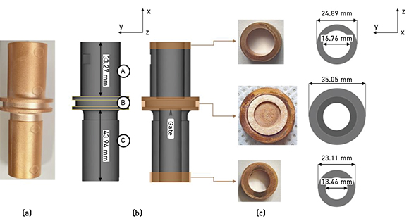
The authors therefore set out to establish guidelines for processing copper powder via the MIM method by scrutinising the role of key MIM parameters including injection pressure, injection temperature, and the gate location to produce the copper green MIM parts. The part used in the study was a pure copper outlet-combo charger terminal body which consisted of two-tube channels with different wall thicknesses and diameters joined together in the middle with a ring-shaped reinforcement (Fig. 1).
Fig. 1 (a) shows the final MIM part, (b) the Moldflow model of the green part, and (c) the final product and Moldflow model along the x-axis. The Moldflow simulation program was again used to predict the flow pattern in the injection moulding process because of its superiority in predicting the flow pattern and providing rapid results. Scanning electron microscopy (SEM) and 3D X-ray computed tomography were used to characterise the surface properties and three-dimensional projection of the interior of the final pure MIM copper product.
Pure copper powder, having a spherical shape and average particle size of 5.2 µm, was mixed with a wax binder at a powder/binder ratio of 95:5 (mass%) which was considered optimum for the MIM feedstock. The feedstock was then injected into the mould cavity using an injection temperature of ~180°C and an injection pressure of ~5 MPa. The injection pressure of ~5 MPa was selected despite the fact that the pressure was outside of the typical low pressure range (10 to 500 kPa) used in MIM for metals with a low viscosity. The feeding system consisted of one specific gate, shown as B in Fig. 1 (b). The authors stated that the positioning of the gate is critical to promote homogeneous distribution of the feedstock in all directions and to mitigate issues relating to binder separation. The green pure MIM copper part underwent debinding at 730°C for 1 h to generate a binder-free product (brown product), which was then sintered at 1050°C for 1 h. The final sintered product was examined for surface analysis, interior analysis, and microhardness.
A computational analysis based on the Moldflow program was used to simulate the effectiveness of the injection moulding process by evaluating the confidence of fill, quality prediction, and pressure drop of three distinctive regions in the green part. The results shown in Fig. 2 suggest that the ring and edge regions of the green parts showed localised behaviour, which was related to processing parameters including the position of the gate.
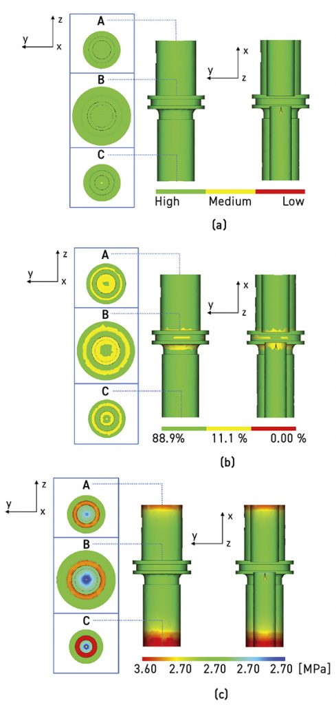
Fig. 2 (a) shows a high value in terms of confidence of fill (green colour) for the whole and half-cut body of the green MIM part. This suggested that the green part will definitely be completely filled and may not have quality problems. Fig. 2 (b) shows a noticeable difference in terms of the quality prediction value for section B of the green part, which the authors suggest might be attributed to a higher level of complexity as compared to sections A and C of the green MIM part. The colour code defined the estimated quality for the green part, such that 88.9%, 11.1%, and 0.00% were the mean values for acceptable, less acceptable, and unacceptable part quality, respectively. A green MIM part with a decreased value of quality prediction will have a higher chance to develop phase separation. Fig. 2 (c) shows the pressure drop especially at the outer edges (as shown in a red colour) of the cylinder in both sections A and C of the green MIM Cu part, which is likely due to an insufficient injection pressure. The authors stated that it is known that the pressure drop is one of the factors that determine the value of confidence of fill.
A microstructural observation using SEM and a 3D X-ray revealed that both the surface and body matrix consisted of pores with some agglomeration of micro-pores on the edges and ring part, while any critical defects, such as a crack, were not found. Consistent with the Moldflow analysis findings, microhardness analysis showed that the three regions exhibited a reasonable uniformity with a slight difference in one specific part mainly due to the localised pore agglomeration. The Moldflow simulation results showed a good agreement with the microstructures and microhardness data and should provide sound guidelines for the production of complex shaped pure copper powder components by MIM.
www.mdpi.com/journal/materials