Optimising your design for MIM production
Several aspects of the MIM component design improve the ease of manufacturing, and there are a number of design features that should be avoided. These are categorised as follows:
Desirable features ✔
- gradual section thickness changes
- wall thickness larger than 0.1 mm but below 10 mm
- low mass
- one flat surface for support during sintering
Allowed design features ✔
- axisymmetric, nonsymmetric, prismatic, square, and freeform features
- cantilever and nonsymmetric shapes
- stiffening ribs and locator features for assembly
- protrusions, bosses, and studs
- most hole shapes are allowed, including blind and through holes
- holes at angles to one another
- undercuts, grooves, slots, depressions
- external teeth, external or internal threads
- knurled and waffle surfaces
- part number or identification logo created by the mould
Features to avoid X
- inside closed cavities
- undercuts on internal bores
- very sharp corners or edges – desired radius greater than 0.05 mm
- long pieces without a draft or taper to allow ejection
- holes under 0.1 mm in diameter
- walls thinner than 0.1 mm
Be aware of size limitations
Some of the limitations arise from the moulding equipment. Massive parts (12 to 17 kg), long components (up to 300 mm), and thick sections (125 mm) have been demonstrated.
In MIM, the component size is not so much an inherent process limitation as an issue from the capacity of the installed equipment and the rapid increase in cost with thick structures, since moulding, debinding, and sintering are all faster with thin walls.
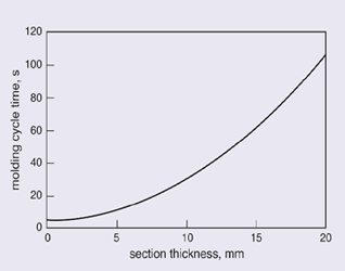
Fig. 7 shows how the moulding cycle time increases with wall thickness. Remembering that time is money, this plot shows the clear advantage in shorter cycle times for designs involving hollowed out components with thinner walls.
Small design modifications can make a big difference
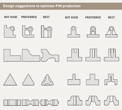
In general, the nearly 30 years of MIM practice have identified several areas where design changes can greatly ease production. A few example cross-section changes are illustrated in Fig. 8.
Another geometric limitation is in the allowed corner and edge radius. Curved surfaces are generally not a problem. But the particle size dictates the edge radius.
Think of placing balls in a box – the size of the ball determines the ability to fill out corners. Stainless steel powders are available down to a few micrometers, but they are costly.
Hence, from a cost standpoint the general driver is toward nominal 20 micrometer powders, negating the production of sharp edges, in spite of the tooling. The limitation on corner and edge radius is 0.05 mm and 0.075 mm is even more realistic. Sharp edges are usually formed by grinding after sintering.
Continue to next page: Further design considerations
Download PIM International magazine
