


Ceramic Injection Molding: The impact of variotherm and conformal cooling technology on part quality and process capability
Despite the success of Ceramic Injection Moulding (CIM) in multiple end-user sectors, from luxury watches to automotive interiors and industrial engineering, there remains considerable scope for process optimisation to advance part quality, productivity and overall process capability. As part of the ‘CIM++’ research project, Ceramaret, Primaform and the iRAP institute investigated the potential of a variotherm control system for the CIM process and, as the results presented here demonstrate, significant improvements were achieved. [First published in PIM International Vol. 18 No. 1, Spring 2024 | 15 minute read | View on Issuu | Download PDF]

Ceramic Injection Moulding (CIM) is one of the best-known and most widely used processes for the manufacturing of technical ceramics. In contrast to conventional machining techniques, CIM presents notable advantages. It facilitates the production of net-shape components through a single forming step that leverages a substantial degree of design flexibility. Additionally, CIM offers enhanced production volumes and rates, which establishes this technology as a highly competitive process characterised by cost-effective manufacturing practices while maintaining a commensurate level of quality.
However, the high viscosity of ceramic feedstocks during the injection phase – a consequence of the high ceramic powder filling of 50 vol.% or more – in conjunction with high thermal conductivity, poses a challenge in the standard Ceramic Injection Moulding process. The main issue is the rapid solidification of the feedstock during the filling stage when it comes into contact with the cooler mould. Such constraints delineate the feasibility limits of the standard CIM process. Notably, these limitations are conspicuous in the production of high-value components that are characterised by intricate geometries like thin-walled structures in the sub-millimetre range and components featuring fine surface details.

The resultant constraints can cause various quality issues like cracking, deformation, warping and optical defects. These can adversely impact production stability and robustness and, therefore, lead to substantial scrap rates.As part of the research project ‘CIM++’, Ceramaret, Primaform and the iRAP institute (Figs. 2, 3) investigated the potential of a variotherm control system for the Ceramic Injection Moulding process and demonstrated significant improvements.

The CIM++ project’s goals
The CIM++ research project was a concerted effort to transcend the aforementioned limitations and enhance the capabilities of CIM technology. This initiative focused on exploring and leveraging the potential of two supplementary technologies: variotherm and conformal cooling, with the aim of improving the capabilities of the Ceramic Injection Moulding process.
Combining CIM and variotherm
To mitigate inherent drawbacks and expand the operational boundaries of CIM, the incorporation of variotherm technology emerges as a compelling prospect. Notably, this technology, prevalent in contemporary plastic injection moulding operations, deviates from conventional injection moulding practices that are characterised by isothermal (constant) mould temperature. The variotherm framework encompasses an enhanced approach through the incorporation of additional heating and cooling stages in the injection moulding cycle.
Compared to standard injection moulding, variotherm mould management is integrated into the injection moulding cycle in the following steps:
- Heating the mould cavity to a temperature close to the melting temperature of the feedstock
- Injection, or filling, of the mould cavity
- Cooling of the mould cavity to the ejection temperature and cooling of the injected part in parallel
- Ejection of the part

Various variotherm systems, ranging from fluid-based (water/oil) induction to infrared-based thermal control, are available on the market and address a wide spectrum of industrial applications.
One well-known advantage of variotherm technology for the plastics industry is the resulting enhanced material fluidity, which leads to reduced injection pressure and lower pressure gradients. Furthermore, this allows for an improved filling length from 40-100% greater and, therefore, the production of components with extremely thin wall thickness. The technology significantly enhances the quality and properties of plastic parts, leading to decreased internal stresses, improved control of shrinkage (dimensions), superior quality of weld lines, and exceptional replication of surface micro- and nanostructures [1,2]. However, it is essential to consider certain drawbacks, such as prolonged cycle time due to the addition of a heat-up/cooling phase in the mould, higher complexity of the mould design and the need for additional equipment (a variotherm system).
A variotherm system, referred to in this study as CIM+, for the injection of ceramic feedstocks at a mould temperature close to its melting point is promising since this method potentially avoids the aforementioned ‘freezing’ of ceramic feedstocks with the cold mould cavities. This preventive measure ensures that the feedstock does not undergo excessively rapid cooling during the filling process, thereby enhancing the overall quality of the injection moulded parts.
Combining CIM, variotherm and conformal cooling
In conjunction with the CIM+ solution, the implementation of conformal cooling, referred to in this study as CIM++, proves advantageous for mould cooling systems featuring intricate part geometries. For conformal cooling, the thermal circuit is optimised to achieve a uniformly distributed mould temperature through the close proximity of the circuit to the cavity. This is achieved by fabricating mould inserts using metal Additive Manufacturing (AM), which gives a high degree of design flexibility for a seamless integration of the cooling channels. Unlike traditional machining methods, such as drilling for the creation of cooling channels, this innovative manufacturing approach offers enhanced freedom for the design of mould temperature management systems [3, 4].
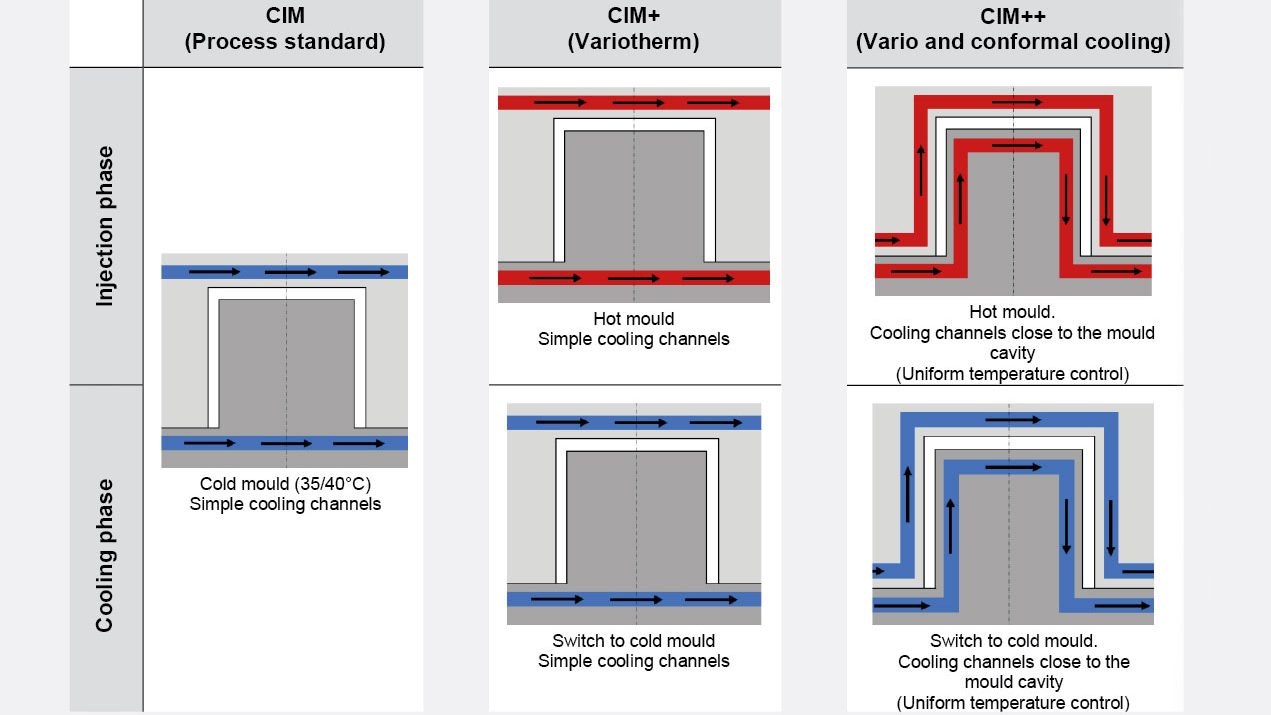
The main benefit of conformal cooling systems is the uniform temperature of the mould cavity, which is adapted to complex 3D geometries and prevents the formation of hot spots. Furthermore, it allows for faster cooling, a reduction of the total cycle time by up to 30%, and significantly improved part quality with less part warpage (more uniform shrinkage) and fewer moulding defects (sink marks). The disadvantages are a time-consuming design phase (including simulations), high fabrication costs of the moulds (only justified for large production volumes) and a high clogging risk of the cooling channels that are difficult to clean.

In the CIM++ project, the potential of both variotherm and conformal cooling systems was explored and benchmarked against the standard CIM process. A ‘proof of concept’ study was conducted in which plates with narrow wall thicknesses (0.3 mm and 0.5 mm) were injected.
Filling study: plate with 0.5 mm wall thickness
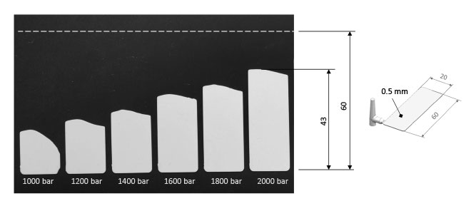
The filling study of plates with a wall thickness of 0.5 mm (dimensions: 0.5 x 20 x 60 mm, sintered) showed that injection pressure as high as 1,000 bar or more only achieved a partial filling of the cavity (Fig. 6). By gradually increasing injection pressure it was possible to improve the cavity fill, but, even at 2,000 bar (near machine limits), it was still incomplete.

On the other hand, a repetition of these tests with variotherm (CIM+) applying different mould temperatures (100°C/125°C/140°C) showed that it was possible to completely fill the cavities applying a higher mould temperature of 125°C and a low injection pressure of 800 bar (Fig. 7). A complete fill of the plate was also possible with a lower mould temperature of 100°C, for which an injection pressure of 1,600 bar was needed.

Filling study: plate with 0.3 mm wall thickness
The filling study based on thinner plates with a wall thickness of 0.3 mm (dimensions: 0.3 x 20 x 60 mm, sintered) demonstrated that, when using the standard CIM process, a flow distance of only 9 mm could be achieved (Fig. 8). With the application of variotherm (CIM+) technology, a significant increase in flow length was achieved. Applying 140°C and 800 bar, the cavity did not fill completely, however, 140°C and 1,200 bar enabled a complete fill. Complete fill of the plates was also achieved at 120°C and 1,600 bar.

Variotherm technology allowed for increased flow lengths so that the mould cavities could successfully be filled while maintaining relatively low injection pressures (800 bar for 0.5 mm and 1,200 bar for 0.3 mm). However, some residual part deformation was encountered after the sintering process (Fig. 9). Applying only variotherm (CIM+), the plates showed deformation that worsened with an increase in injection pressure. This part problem was successfully eliminated when applying a combined variotherm and conformal cooling (CIM++), resulting in flat plates after sintering. Deformation when using CIM+ was approx. 230 µm, and with CIM++ approx. 20 µm.

A Moldflow simulation was conducted to study the impact of the variotherm heating of the mould cavity before filling, compared to a combined variotherm and conformal heating. At t=13 seconds, inhomogeneous temperature of the mould cavity was noted with differences up to 60°C for pure variotherm that were reduced to 30°C when using the combined variotherm and conformal cooling (Fig. 10).

This mould temperature inhomogeneity is critical and creates internal stresses leading to greater deformation. With conformal cooling, a significant advantage was observed with a more uniform mould temperature. These conditions are optimal for a more homogeneous cooling of the injected feedstock, a reduction of internal stress and, therefore, less warpage.
Potential for replication of fine structures
![Fig. 11 Quality of the replication of a holographic structure with standard (CIM) and compared with variotherm (CIM+) (Courtesy iRAP Institute, HEIA-FR/HES-SO, Morphotonix [5]). Measured mean height of the structure in the mould cavity: 0.42 µm. Expected mean height of the structure on injected ceramic parts after debinding/sintering: 0.32 µm. Measured mean height of the structure realised with CIM standard: 0.23 µm. Measured mean height of the structure realised with CIM and variotherm (CIM+): 0.28 µm](https://www.pim-international.com/wp-content/uploads/sites/2/2025/01/f11-edited.jpg)
The application of variotherm technology is also enabling the successful replication of submicron surface details, such as holograms, through the Ceramic Injection Moulding process. The dimensions of the replicated structures corresponded approximately to the dimensions of the original mould texture when the feedstock shrinkage ratio was considered (Fig. 11). This high-quality replication is impossible with a standard CIM process. These tests have shown the significant potential of variotherm technology to integrate functional or decorative structures on CIM parts.

Conclusions
The exploration of innovative technologies such as variotherm and conformal cooling in Ceramic Injection Moulding through the CIM++ project has demonstrated the significant potential of these technologies for overcoming the limitations associated with the standard CIM process. The challenges faced in producing components with very thin walls, replicating fine surface details, and addressing quality issues such as cracking, deformation, and optical defects, have been effectively addressed.
![Fig. 12 A comparison of the quality of the replication of a holographic structure with standard CIM and variotherm (CIM+) (Courtesy iRAP Institute, HEIA-FR/HES-SO, Morphotonix [5])](http://www.pim-international.com/wp-content/uploads/sites/2/2025/01/f12-1-1024x259.jpg)
Variotherm technology, widely used in plastic injection moulding, has shown promising results for the CIM process by introducing additional heating and cooling steps to the mould cavity. This has highlighted several advantages, including increased fluidity of the ceramic material, lower injection pressure, higher flow lengths and the ability to produce parts with very thin wall thickness in the range of a few tenths of a millimetre. Previous technical feasibility limits for thin-walled ceramic components can now be extended. Despite longer cycle times and increased mould design complexity, the benefits in terms of improved part quality, reduced internal stress, and better shrinkage control highlight the potential of the variotherm process for CIM.
Furthermore, the integration of conformal cooling systems, which involve the use of thermal circuits to achieve uniform mould cavity temperatures, has driven remarkable improvements in part quality. Conformal cooling imparts a uniform mould cavity temperature for complex geometries with fewer hot spots, faster cooling and a reduction of the total cycle time. Despite the associated time-consuming design phases and higher mould fabrication costs, the advantages of conformal cooling in terms of improved part quality, reduced internal stresses, and fewer moulding defects make it a valuable addition to the CIM process.
Authors
Bruno Bürgissera, Tristan Rüegera, Senad Hasanovicb, Thomas Terrillonb, Kay Beuretc and Claudio Ferraro
a iRAP, Institute for Applied Plastics Research, HEIA-FR (HES-SO)
Fribourg
Switzerland
b Ceramaret SA
Bôle
Switzerland
c Primaform AG
Thun
Switzerland
Contact
HEIA-FR (HES-SO), iRAP Institute
Prof. Bruno Bürgisser
Passage de Cardinal 1
CH-1700 Fribourg
Tel: +41(26)429 66 59
[email protected]
www.heia-fr.ch/fr/recherche-appliquee/instituts/irap/
Ceramaret SA
Rue des Croix 43
CH-2014 Bôle
Primaform SA
Tempelstrasse 14
CH-3608 Thun
Acknowledgements
The authors would like to thank Innosuisse (Swiss Agency for Innovation), for its financial support of the research project CIM++ (57563.1 IP-ENG).
References
[1] Berlin W, et al. variothermie im Wandel der Zeit – Entwicklungstrends in der dynamischen Temperierung von Spritzgiesswerkzeugen. Kunststoffe 8/2019. Carl Hanser Verlag
[2] Müller-Köhn A. variotherme Spritzgiesstechnologie. Fraunhofer IKTS
[3] Kircheim A, et al. Dynamic conformal cooling improves injection moulding. The International Journal of Advanced Manufacturing Technology (2021) 114:107–116
[4] Shaochuan F, Amar M.K, Yuato P. Design and fabrication of conformal cooling channels in moulds: Review and progress updates. International Journal of Heat and Mass Transfer 171 (2021)
[5] Morpothonix, https://morphotonix.com/


